ENERCORP AQT-2000 User manual

-1-
ENERCORP
AIR QUALITY MONITOR
Installation and Operation Manual
TABLE OF CONTENTS
1. Air Quality Components
2. Component Fun tion
3. Programming
4. Data Logging
5. Transferring data to a PC or MAC
6. Wiring & Te hni al Data
7. History of Air Quality
8. Comparison with CO2
9. Portable lass room appli ation
1. AIR QUALITY COMPONENTS
a) Order number AQT-S-2000. A ream oloured
instrument resembling a thermostat alled the air
quality monitor or AQT.
This instrument an be ordered fa tory programmed
or programmed in the field with a hand-held module.
b) Order number HHM-AQ. A bla k instrument
with keypad and alpha-numeri display, alled a
hand-held module or HHM.
If you wish to log data or modify the program of
AQT-2000’s you will need one of these. Only one
of these will be required per site or per servi e
representative.
) Order number AQT-DEMO-KIT. A bla k
sample ase ontaining a pre-wired power module
and analogue meter onne ted to a hand held module
and air quality monitor.
This is a onvenient way to test drive the AQT-2000
to verify to yourself that it is effe tive in your
installation. Sin e it is omplete with a highly visible
readout indi ator it is a very effe tive way to provide
lient demonstrations.
d) Order number AQT-SERIAL-KIT. Cables and
software to permit data from the air quality system to
be downloaded to a PC and graphed.
2. COMPONENT FUNCTION
a) The AQT-2000 monitors and ontrols air
quality. It senses volatile organi ompounds,
VOC’s. People breath out VOC’s, in luding
ketones. Building materials out-gas VOC’s su h as
formaldehyde from arpets and hip board. The
AQT-2000 is therefore a good sensor of air quality
deterioration due to both o upan y and hemi als in
the work pla e.
If you hoose CONTROLLER while setting up the
AQT-2000 it will respond qui kly to any worsening
of air quality but rea t slowly to improvements in air
quality. This is to insure that any ontaminants are
flushed from the monitored spa e. CONTROLLER
should be sele ted for appli ations su h as portable
lassrooms where one AQT-2000 will be dire tly
onne ted to a fresh air damper a tuator to ontrol air
quality.
If you hoose TRANSMITTER it will produ e an
analogue voltage or urrent signal proportional to the
sele ted range of air quality you wish to monitor .
TRANSMITTER should be sele ted if several AQT-
2000 monitors will transmit signals to a entral
ontrol system whi h will de ide on the appropriate
a tion to take to ontrol air quality.
ENERCORP instruments ltd
25 Shorncliffe Rd, Toronto, ON, M9B 3S4, Canada
Tel(416)231 5335 Fax (416)231 7662
Tel(800)ENERCORP Fax (877)ENERCORP

-2-
b) The HHM intera ts with you to SETUP
operating parameters to mat h your installation. It
stores these parameters in non-volatile memory. You
an then SEND these parameters to the AQT-2000.
The HHM an also LOG data from the AQT-2000
and later DUMP it to a personal omputer. The
HHM is only used for SETUP and LOGGING of air
quality. It has no monitoring or ontrol fun tion and
an be dis onne ted from the installation on e the
AQT-2000 is programed. It is powered by the AQT-
2000.
) The demo kit ontains a 4 to 20mA analogue
panel meter onne ted to the urrent output of the
AQT-2000. In a typi al installation this 4 to 20 mA
signal would be fed dire tly to a damper a tuator to
ontrol its position.
The power supply powers the AQT-2000. It an be
plugged into any 110V outlet to operate the
demonstration kit. In permanent installations the
AQT-2000 requires a 12 to 30VDC power supply.
d) The hand held module has a serial output that
an be atta hed to the serial port of an IBM
ompatible PC or Ma intosh omputer. We offer a
pa kage ontaining a data download able whi h
powers a hand-held module and onne ts it to a PC
to download stored data to the graphing pa kage we
supply.
You an also use your own ommuni ations,
graphing and spreadsheet software for omplex
analysis.
If you have a real-time graphi al pa kage you an use
the supplied “Y” able to onne t the AQT-2000 and
the HHM-AQ to your PC to monitor and save air
quality data in real-time.
If you will be using a Ma intosh omputer you will
need to extend the supplied able with a null modem
onne tor and a MAC serial modem able. We
suggest you use Claris Works for ommuni ation
and graphing or use the harting software we supply
under Soft Windows.
3. PROGRAMMING
The AQT-S-420 and AQT-D-420 are fa tory
alibrated and programmed before delivery to the
ustomer. The analogue output hanges
proportionally to pollution level. If a 4-20mA output
has been hosen 4mA represents the best possible air
and 20mA represents the worst.
We use medi al air to alibrate the 4mA setting.
Readings this good will not normally be a hieved in
operating onditions. Readings of 8mA or less
indi ate ex ellent indoor air quality while 16mA or
more is poor.
In general pra ti e anything less than 1/3 s ale
(9.3mA) is usually onsidered very good and not in
need of any a tion. Between 1/3 and 2/3 s ale
(14.6mA) progressive stages of filtering or leaning
are employed to improve air quality. Suffi ient fresh
air is normally introdu ed to prevent air quality
readings ex eeding 2/3 s ale (14.6mA).
Although the air quality monitor is ready for
operation as re eived from the fa tory the available
hand held module serial kit are valuable tools to log
and graph air quality data to determine if and where
air quality monitors should be used. the hand held
module an also be used to re onfigure
or re alibrate an air quality monitor.
The following se tion des ribes the use of the hand-
held module and graphi al software. If you are
simply installing an air quality monitor you an skip
to se tion 6, whi h des ribes wiring hook up.
When powered on the HHM will display:
SELECT FUNCTION
SEND flashing
As you press the up/down arrow key SEND will
toggle to SETUP, DUMP , LOG and ba k to
SETUP
The first time the HHM is used press the up/down
arrow key until SETUP is displayed. Then press the
green enter key.
The unit will display:
HOW WILL AQT BE USED
TRANSMITTER flashing
As the up/down arrow key is pressed
TRANSMITTER toggles to CONTROLLER and
ba k again. Press the green ENTER key to sele t
your hoi e.
CONTROLLER should be hosen for use in a
portable lassroom or similar appli ation where the
AQT will monitor the onditions in a single room and
dire tly ontrol a fresh air damper to maintain air
quality. In this mode the AQT rea ts very qui kly to
hanges in air quality so it an provide additional
fresh air as more o upants enter a room or the
a tivity level in reases in the room.
TRANSMITTER should be hosen if several AQT’s
will send an analogue signal representing air quality
ba k to a entral ontrol system whi h will perform
the ontrol fun tion. In this mode the air quality
monitor produ es an analogue output signal
proportional to a user defined se tion of the air
quality spe trum.
If you hoose CONTROLLER go to A
If you hoose TRANSMITTER skip se tion A and
go to B

-3-
A
The unit will display:
TYPE OF OUTPUT
4...20MA flashing
The up/down arrow key toggles 0...10V to 4...20ma
and ba k. Press enter to a ept your hoi e.
The display will now read:
TYPE OF OUTPUT
CONTINUOUS flashing
The up/down arrow toggles from CONTINUOUS
to STEPPED. Press enter when the desired value is
sele ted. Continuous gives an output signal that
varies ontinuously from zero to full s ale. Stepped
gives an output signal in steps equal to the values
spe ified in the GOOD, FAIR, POOR and BAD
parameters. Choose ontinuous normally.
The display now reads:
SENSITIVITY 100 MOST
XX % flashing
Press up/down to display desired value, then press
ENTER to a ept the value. This parameter fine
tunes an AQT-2000 for a parti ular lo ation. Start
with 25. If the instrument responds too qui kly to
hanges in air quality lower the value, if too slowly
in rease the value. After hanging the value you
must SEND the new program to the AQT.
The unit now displays:
SET GOOD AIR OUTPUT
XX % flashing
Enter the desired value on the keypad. Press
ENTER to a ept the value. Sele ting 10% would
open the damper on a s hool portable 10% to provide
fresh air at all times even if the air quality was good.
The HHM will display:
SET FAIR AIR OUTPUT
XX % flashing
Press up/down to display desired value, then press
ENTER to a ept the value. If you sele t 33, the
AQT-2000 output will be 33% of full s ale or open a
damper 33% when the air quality is fair.
The display then reads:
SET POOR AIR OUTPUT
XX % flashing
Press up/down arrow to display desired value and
press ENTER to a ept the value. Try 66 to start.
The unit now displays:
SET BAD AIR OUTPUT
XX % flashing
Press the arrow key until the display shows the
desired value and then press ENTER to a ept the
value. If you sele t 100, the AQT output will be
100% of full s ale when the air quality is bad.
Skip se tion B and go dire tly to se tion C.
B
The unit will display:
TYPE OF OUTPUT
4...20MA flashing
The up/down arrow key toggles from 0...10V to
0...5V to 4...20mA and ba k again. Press enter to
a ept your hoi e.
The display will now read:
CHOOSE SCALE START
99999
This is the larger of the two numbers you enter to set
the analogue output s ale range. It an have a
maximum value of 39999. As a starting point try
20,000 to 30,000. Press the enter key when the
desired value is sele ted.
The display will now read:
CHOOSE SCALE END
99999
This is the smaller of the two numbers you enter to
set the analogue output s ale range. It an have a
value from zero up to near the value spe ified above.
As a starting point try 5,000 to 10,000 for lean
living spa es or zero for spa es that may have very
high on entrations of VOC’s Press the enter key
when the desired value is sele ted.
Pro eed to se tion C.
C
The display will read :
SETUP COMPLETE
then
SELECT FUNCTION
SEND flashing
The program has now been entered in the HHM,
hand held module. It has not been entered into the
AQT-2000, air quality monitor.
If you are happy with the entered program and wish
to send it to the AQT-2000. Press the green ENTER
key while SEND is flashing.
The program in the HHM will be sent to the monitor
and the display will read
DEVICE PROGRAMMED
PRESS ANY KEY
It is possible to get an ERROR message at this point
if the data has not been properly transmitted to the
AQT-2000. If this o urs he k the Tel o
onne tion and press the ENTER key again until you
get the DEVICE PROGRAMMED message.
You an dis onne t the HHM now. It will retain its
program and an be used to program other AQT-
2000 modules later.

-4-
4. DATA LOGGING
The HHM an be used as a data logger to re ord air
quality and later dump it into your PC.
To enter data logging mode use the up/down arrow
key while in the SELECT FUNCTION s reen until
you get the following display
SELECT FUNCTION
LOG flashing
Press ENTER.
The display now reads
YYMMDDHHMM SET TIME
9 9 9 9 9 9 9 9 9 9
where 9999999999 is the urrent date and time
Use the up arrow key to move the ursor and the
numeri keypad to hange the values. Press enter to
a ept the displayed value.
The display now reads
5 s flashing
Toggle through the available hoi es with the up/
down arrow key. Press enter when your hoi e is
displayed. THE HHM an log for 12 hours at 1
minute intervals or 4 weeks at 60 minute intervals.
The display will read:
SET LOG OPTION
0 flashing
Press ENTER, this option is only used for fa tory
setup.
BEGIN LOGGING NOW?
PRESS ENTER TO BEGIN flashing
When you press ENTER
The display will read :
LOGGING: . TO STOP
99999
The HHM is logging data. To stop data logging
press the period key. 99999 is a number between 0
and 32000. This number is a measure of air quality.
The larger the number the better the air quality. You
may find it useful to look at this number to see
instantaneous hanges in air quality.
5. TRANSFERRING DATA to a PC or MAC
If you want to do this you will need the required
onne tor and ommuni ations software.
1. We offer a relatively user friendly software
pa kage that runs under Windows 3.1 on a PC or
Soft Windows on a MAC. It an read data from the
handheld module while onne ted to the omputer’s
serial port. On e the data is read the program
automati ally s ales the data, displays a graph on the
s reen and allows you to save and/or print it. This is
a very simple and effe tive way to qui kly view
trends in air quality over a time period. For more
omplex analysis of the data you an save the data
and use your spread sheet program for analysis.
SERIAL COMMUNICATIONS
If you have pur hased the AQT-SERIAL-KIT you
will have a able with power supply to onne t the
HHM-AQ to a COM port of your your PC. You will
also have a floppy diskette with software to read and
graph the data you have logged with the HHM-AQ.
Before using the ommuni ations program ensure
that
the COM port you want to use is working properly
under
Windows. Use a ommuni ations program su h as
the
Windows TERMINAL (or XTALK, PROCOMM
et .) to verify
that you an properly 'DUMP' the data to the PC.
Set the ommuni ations port to ...
8 data bits
1 stop bit
n no parity
9600 baud
Use COM 1,2,3 or 4 (usually 1 and 2 have interrupt
apability
and often COM 1 is used by the Mouse, it is
re ommended to use
COM 2 if available)
The sample DUMP data should look like this...
DUMP 96/03/28 20:06 @ 5s
AIRQ, TEMP, HUM, OUT.
25023 09246 22985 00043
25047 09246 22985 00043
25067 09247 22986 00043
25094 09248 22987 00043
25105 09247 22989 00043
25119 09247 22990 00043
25129 09247 22992 00042
25141 09246 22993 00042
25153 09246 22994 00042
To enter down loading mode use the up/down
arrow key while in the SELECT FUNCTION s reen
until you get the following display
SELECT FUNCTION

-5-
DUMP flashing
Conne t the HHM to the serial port of your omputer
with the appropriate able.
Run the supplied graph program under windows and
press the CAPTURE button when it is displayed. A
field at the bottom of the s reen will display
CAPTURE ON.
At this time press the green enter key on the HHM.
The HHM-AQ display will read :
DUMP
OUTPUT flashing
When all the data has been transferred to your
omputer
The display will read
SELECT FUNCTION
SEND flashing
The data is retained in the HHM and an be dumped
again if desired. Stored data is only erased when the
you begin logging again.
The omputer s reen will display a graph of the data.
You an then print the data by pressing the PRINT
button on the s reen.
The supplied graphing program is intended to
provide a very straight forward method of graphing
data. If more omplex analysis of the data is
required you an press the SAVE button and opy
the data into your spread sheet appli ation.
After he king for proper onne tions and
ommuni ation
1. Run the GRAPH.EXE program
2. Sele t the orre t COM port
3. Set CAPTURE to ON
4. 'DUMP' the data from the HHM.
5. When all data is re eived a graph will display on
your s reen
6. The s reen has buttons to PRINT the graph and
to SAVE the data to a file.
7. You an later load the saved file into your
spreadsheet for more omplex analysis.
The instrument has logged four fields of data. 1 is
air quality, 2 is temperature, 3 is humidity and 4 is
the analogue output. All values should be used to
establish trends. The absolute values on the s ales
are arbitrary. On e a graph is displayed use the
COM Port buttons to sele t the data field you wish to
view.
6. IRING & TECHNICAL DATA
Supply Voltage 12 to 30 VDC
Supply Current 100 mA
Operating temperature -10 to 60 C
Operating Humidity 10 to 95% rH
Outputs 4 to 20mA / 0...10 VDC
Output Impedan e > 1k ohms for voltage
1000*Vs/24 for urrent
Note about outputs: Both the urrent and voltage
outputs are always available
They are independent but
their s ales are related. If you
sele t 4-20mA you will also
get a 2 to 10V output. If you
sele t 0 to 10V out you will
also get 0 to 20mA out.
If you sele t 0 to 5V you will
also get 0 to 10 mA out.

-6-
P
O
WER SUPPLY
4 to 20mA
INDICATOR
COMPUTER
AQT
TRANSMITTER
- ++ -
P
OWER SUPPLY
V
OLTS IN
I
NDICATOR
C
OMPUTER
A
QT TRANSMITTER
-
+
+
-
P
OWER SUPPLY
4
to
20
m
A
INDICATOR
COMPUTER
A
QT TRANSMITTER
+ -
+
-
P
OWER SUPPLY
AQT TRANSMITTER
+ -
+
-
V
OLTAGE INPUT
I
NDICATOR
C
OMPUTER
Versions manufa tured before September 1996
Versions manufa tured after September 1996
Table of contents
Popular Control System manuals by other brands

Ingeteam
Ingeteam INGECON SUN EMS Board Installation and configuration
Crestron
Crestron TPCS-4SM Configuration guide
Roger
Roger IOS-1 user manual
Norac
Norac UC4.5 installation manual
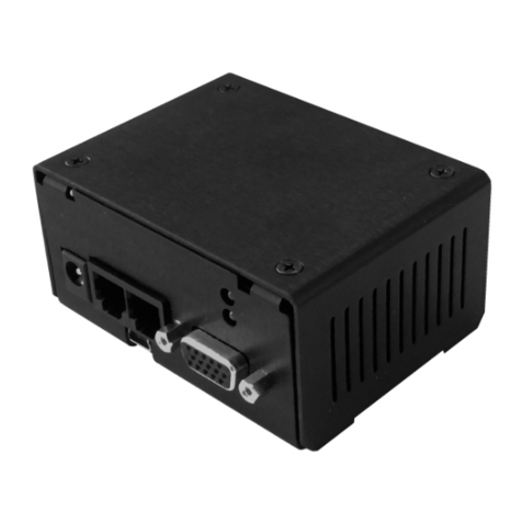
Micronix
Micronix MMC-10 Series Reference manual

Schweitzer Engineering Laboratories
Schweitzer Engineering Laboratories SEL-421-7 manual
