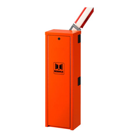
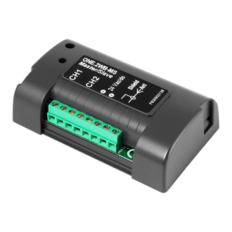
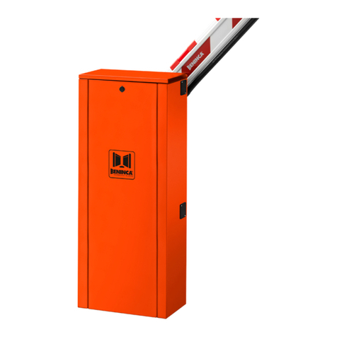
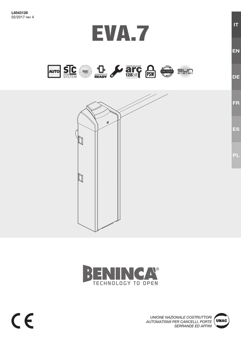
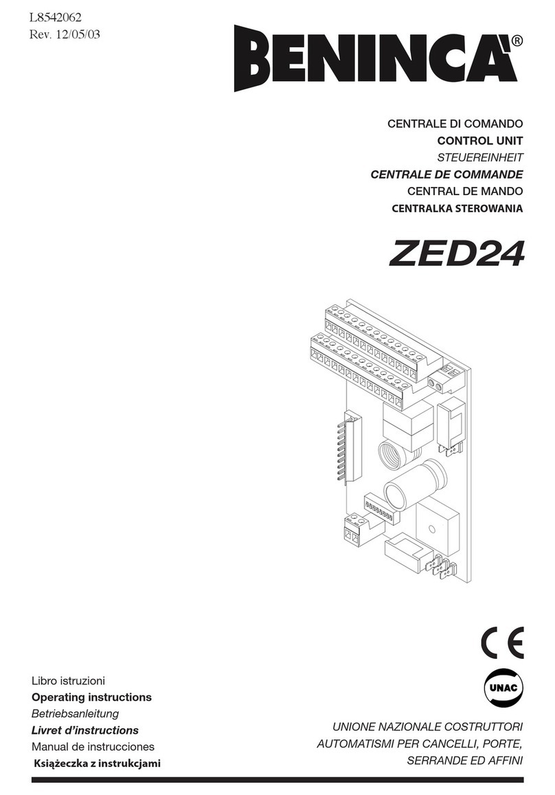
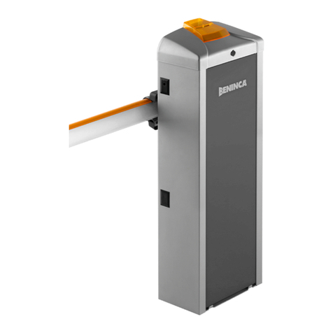
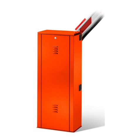
Beninca DA.24V User manual

L8542067
02/2013 rev 9
UNIONE NAZIONALE COSTRUTTORI
AUTOMATISMI PER CANCELLI, PORTE
SERRANDE ED AFFINI
DA.24V / CP.EVA

2
DA.24V
M
RADIO
230Vac
50/60Hz
NL
S1
L1
VAUX VMOT
0
N1
COM
P.P.
OPEN
PHOT
SWC
SWO-R
SWC-R
STOP
CLOSE
SHIELD
ANT
ANT
24Vac
500mA max
111098765 1312 14 15 16 174
21201918 2524
2829
SLWCL SLWOP AMP TCA
F2
F1
T1A
230V:T1.6A
120V:T3.5A
18
26
23
23N
L
0
18
LAMP
24Vac
BAR
LIGHT
24Vdc
STP
POWER
PH OP CH PP
SWC-R
SWO-R
SWC
(+) (-)

3
CP.EVA
M
RADIO
230Vac
50/60Hz
S1
VAUX VMOT
0
COM
P.P.
OPEN
PHOT
SWC
SWO-R
SWC-R
STOP
CLOSE
SHIELD
ANT
ANT
24Vac
500mA max
111098765 1312 14 15 16 174
21201918 2524
2829
SLWCL SLWOP AMP TCA
F1
T1A
18
26
23
23
0
18
LAMP
24Vac
BAR
LIGHT
24Vdc
STP
POWER
PH OP CH PP
SWC-R
SWO-R
SWC
(+) (-)
N
L
F2:1,6AT (230V)
F2:3,5AT (115V)

4
Dichiarazione CE di conformità
Dichiarazione in accordo alle Direttive 2004/108/CE(EMC); 2006/95/CE(LVD)
Fabbricante: Automatismi Benincà SpA.
Indirizzo: Via Capitello, 45 - 36066 Sandrigo (VI) - Italia
Dichiara che il prodotto:
Centrale di comando per 1 motore 24Vdc, per barriera stradale: DA.24V - CP.EVA
è conforme alle condizioni delle seguenti Direttive CE:
• DIRETTIVA 2004/108/CE DEL PARLAMENTO EUROPEO E DEL CONSIGLIO del 15 dicembre 2004
concernente il ravvicinamento delle legislazioni degli Stati membri relative alla compatibilità elettromagnetica e
che abroga la direttiva 89/336/CEE, secondo le seguenti norme armonizzate:
EN 61000-6-2:2005, EN 61000-6-3:2007.
• DIRETTIVA 2006/95/CE DEL PARLAMENTO EUROPEO E DEL CONSIGLIO del 12 dicembre 2006
concernente il ravvicinamento delle legislazioni degli Stati membri relative al materiale elettrico destinato ad essere
adoperato entro taluni limiti di tensione, secondo le seguenti norme armonizzate:
EN 60335-1:2002 + A1:2004 + A11:2004 + A12:2006 + A2:2006 + A13:2008; EN 60335-2-103:2003.
se applicabile:
• DIRETTIVA 1999/5/CE DEL PARLAMENTO EUROPEO E DEL CONSIGLIO del 9 marzo 1999 riguardan-
te le apparecchiature radio e le apparecchiature terminali di telecomunicazione e il reciproco riconoscimento della
loro conformità, secondo le seguenti norme armonizzate: ETSI EN 301 489-3 V1.4.1 (2002) + ETSI EN 301 489-1
V1.4.1 (2002) + ETSI EN 300 220-3 V1.1.1 (2000) + EN 60950-1 (2001)
Benincà Luigi, Responsabile legale.
Sandrigo, 02/11/2010.
AVVERTENZE
Questo manuale è destinato esclusivamente a personale
qualificato per l’installazione e la manutenzione di aperture
automatiche.
Nessuna informazione qui presente è di interesse o di
utilità per l’utente finale.
Conservare questo manuale per futuri utilizzi.
L’installatore deve fornire tutte le informazioni relative
al funzionamento automatico, manuale e di emergenza
dell’automazione, e consegnare all’utilizzatore dell’im-
pianto le istruzioni d’uso.
•Prevedere sulla rete di alimentazione un inter-
ruttore/sezionatore onnipolare con distanza
d’apertura dei contatti uguale o superiore a 3 mm.
Verificare che a monte dell’impianto elettrico vi sia un interrut-
tore differenziale e una protezione di sovracorrente adeguati.
Alcune tipologie di installazione richiedono il collegamento
dell’anta ad un impianto di messa a terra rispondente alle
vigenti norme di sicurezza.
L’installazione elettrica e la logica di funzionamento devono
essere in accordo con le normative vigenti.
I conduttori alimentati con tensioni diverse, devono
essere fisicamente separati, oppure devono essere
adeguatamente isolati con isolamento supplementare di
almeno 1 mm.
I conduttori devono essere vincolati da un fissaggio sup-
plementare in prossimità dei morsetti.
Durante gli interventi di installazione, manutenzione e
riparazione, togliere l’alimentazione prima di accedere
alle parti elettriche.
Ricontrollare tutti i collegamenti fatti prima di dare ten-
sione.
Gli ingressi N.C. non utilizzati devono essere ponticellati.
Le descrizioni e le illustrazioni presenti in questo manuale
non sono impegnative. Lasciando inalterate le caratteri-
stiche essenziali del prodotto il fabbricante si riserva il
diritto di apportare qualsiasi modifica di carattere tecnico,
costruttivo o commerciale senza impegnarsi ad aggiornare
la presente pubblicazione.
5
DATI TECNICI
Alimentazione centrale di comando 24 Vdc
Alimentazione di rete 230 Vac 50/60 Hz
Uscita Motore 1 motore 24Vdc
Potenza massima motore 120 W
Uscita alimentazione accessori 24Vdc 500mA max.
Grado di protezione IP54
Temp. funzionamento -20°C / +50°C
Ricevitore radio Connettore ad innesto per ricevente radio.
Centrale di comando DA.24V/CP.EVA
FUNZIONI INGRESSI/USCITE
N° Morsetti Funzione Descrizione
1-2 Alimentazione Ingresso 230Vac 50/60Hz (1-Neutro/2-Fase)
4-5 Motore 24Vdc Collegamento al motore 24Vdc
6-7 Lampeggiante Collegamento lampeggiante 24Vac 40W max.
8-9 24 Vac
Uscita alimentazione accessori 24Vac/0,5A max.
ATTENZIONE: Nel caso di installazione della scheda caricabatte-
ria CB.24V, l’uscita (in assenza di alimentazione di rete) presenta
una tensione 24Vdc - polarizzata. Verificare il corretto collega-
mento dei dispositivi (8:+24Vdc - 9:-24Vdc).
10-11 Luci barriera Collegamento luci asta barriera 24Vdc (10+/11+) -200mA max
(equivalenti a circa 6 luci).
12 COM Comune per tutti gli ingressi di comando.
13 STOP Ingresso pulsante STOP (contatto N.C.)
14 PHOT Ingresso collegamento dispositivi di sicurezza, contatto N.C.
(ad es. fotocellule)
15 OPEN Ingresso pulsante APRE (contatto N.O.)
16 CLOSE Ingresso pulsante CHIUDE (contatto N.O.)
17 Passo-Passo Ingresso pulsante passo-passo (contatto N.O.)
18 COM Comune finecorsa.
19 SWC
Ingresso finecorsa CHIUSURA (contatto N.C.).
L’apertura di questo contatto interrompe l’alimentazione al moto-
re al termine della manovra di chiusura della barriera.

6
20 SWO-R
Ingresso finecorsa rallentamento in apertura (contatto N.C.).
Con l’apertura di questo contatto ha inizio la fase di rallentamen-
to in apertura della barriera.
21 SWC-R
Ingresso finecorsa rallentamento in chiusura (contatto N.C.).
Con l’apertura di questo contatto ha inizio la fase di rallentamen-
to in chiusura della barriera.
24-25 Antenna
Collegamento antenna scheda radioricevente ad innesto
(24-segnale/25-schermo).
28-29 2°Ch radio Uscita contatto N.O. del secondo canale radio.
VAUX-0-VMOT Secondario Collegamento avvolgimento secondario trasformatore
L1-N1 Primario Collegamento avvolgimento primario trasformatore
J3 Ricevitore Radio Connettore ad innesto per ricevente radio.
FUNZIONE DEI TRIMMER
SLOWCL Regola la velocità del motore durante la fase di rallentamento in chiusura.
Il rallentamento inizia con l’intercettazione del finecorsa SWC-R e termina con l’intercettazione
del finecorsa SWC.
SLOWOP Regola la velocità del motore durante la fase di rallentamento in apertura.
Il rallentamento inizia con l’intercettazione del finecorsa SWO-R e termina dopo il tempo
impostato con il Dip-Switch N°8.
AMP Regola la sensibilità del sensore amperometrico di rilevamento ostacolo.
Il sensore è attivo in apertura e in chiusura.
Non è attivo durante la fase di rallentamento in apertura.
In caso rilevamento ostacolo:
In fase di apertura ferma la barriera.
In fase di chiusura ferma e riapre completamente.
TCA Permette di regolare il tempo di chiusura automatica se attivata dal Dip-Switch N°1.
La regolazione varia da un minimo di 1s ad un massimo di 90s
FUNZIONE DIP-SWITCH
DIP 1 “TCA” Abilita o disabilita la chiusura automatica.
Off: chiusura automatica disabilitata
On: chiusura automatica abilitata
DIP 2 “PRELAM.” Abilita o disabilita il prelampeggio
Off: Prelampeggio disabilitato
On: Prelampeggio abilitato. Il lampeggiante si attiva 3s prima della partenza del
motore.
DIP 3 “SCL” (DIP1 deve essere ON) Abilita o disabilita la funzione chiusura rapida dopo
fotocellula.
Off: Funzione disattivata. Dopo l’intervento della fotocellula, il tempo della chiusura
automatica resta invariato.
On: Funzione Chiusura rapida attivata. Dopo l’intervento della fotocellula, il tempo
della chiusura automatica si riduce a 1 secondo.
DIP 4 “P.P. Mod” Seleziona la modalità di funzionamento del ”Pulsante P.P.” e del trasmettitore.
Off: Funzionamento: APRE > STOP > CHIUDE > STOP >
On: Funzionamento: APRE > CHIUDE > APRE >

7
DIP 5 “LIGHT” Seleziona la modalità di funzionamento delle luci barriera collegate ai morsetti
10/11.
Off: Lampeggio lento con barriera aperta o chiusa. Lampeggio veloce durante il
movimento.
On: Luce accesa fissa con barriera aperta o in movimento. Luce spenta a barriera
chiusa, comandata dall’intervento del finecorsa SWC-R.
DIP 6 “COND.” Abilita o disabilita la funzione condominiale.
Off: Funzione condominiale disabilitata.
On: Funzione condominiale abilitata. L’impulso P.P. o del trasmettitore non ha
effetto durante la fase di apertura e durante la fase TCA (se attivata).
DIP 7 “AMPCL” Abilita o disabilita il sensore amperometrico durante la fase di rallentamento in
chiusura.
Off: Sensore amperometrico abilitato durante la fase di rallentamento in chiusura.
On: Sensore amperometrico disabilitato durante la fase di rallentamento in
chiusura.
DIP 8 “Trall-OP” Attiva o disattiva il sensore amperometrico in fase di rallentamento in apertura.
Off: Rallentamento di 2s con sensore amperometrico non attivo.
On: Rallentamento di 2s, con sensore amperometrico attivo. L’intervento del
sensore amperometrico durante i 2s di rallentamento comporta l’arresto immediato
della barriera.
Nel caso si renda necessario è possibile il comando dell’automazione in modalità UOMO PRESENTE
ponendo tutti i DIP in ON.
REGOLAZIONE DELLA VELOCITÀ BARRIERA
ATTENZIONE! Questa regolazione influisce sul grado di sicurezza dell’automazione.
Verificare che la forza applicata sull’asta sia conforme con quanto previsto dalle normative vigenti.
Ogni modifica della velocità richiede una nuova taratura del sensore amperometrico.
Sul trasformatore di alimentazione è presente un connettore Faston (VMOT) che permette la regolazione
della velocità della barriera dei motori su 3 diversi livelli (18-23-26).
Posizionando il Faston (VMOT) su 18 si ha la velocità minore, spostandolo su 26 si ha la velocità
maggiore.
Nel caso di sia presente l’appoggio mobile VE.AM o la rastrelliera VE.RAST, ridurre la velocità dell’asta.
DIAGNOSTICA LED
La centrale dispone di una serie di LED di autodiagnosi che consentono il controllo di tutte le funzioni:
Led POWER Lampeggia a segnalare la presenza di alimentazione di rete
Led STOP Si spegne con l’attivazione del pulsante STOP
Led PHOT Si spegne con fotocellule non allineate o in presenza di ostacoli
Led OPN Si accende con l’attivazione del pulsante OPEN
Led CLS Si accende con l’attivazione del pulsante CLOSE
Led PP Si accende con l’attivazione del pulsante PP
Led SWC Si spegne con l’attivazione del finecorsa di chiusura SWC
Led SWO-R Si spegne con l’attivazione del finecorsa di rallentamento apertura SWO-R
Led SWC-R Si spegne con l’attivazione del finecorsa di rallentamento chiusura SWC-R
SMALTIMENTO
Qualora il prodotto venga posto fuori servizio, è necessario seguire le disposizioni legislative in vigore al
momento per quanto riguarda lo smaltimento differenziato ed il riciclaggio dei vari componenti (metalli,
plastiche, cavi elettrici, ecc.); è consigliabile contattare il vostro installatore o una ditta specializzata ed
abilitata allo scopo.

8
EC declaration of confirmity
Declaration pursuant to Directives 2004/108/EC(EMC); 2006/95/EC(LVD)
Manufacturer: Automatismi Benincà SpA.
Address:
Via Capitello, 45 - 36066 Sandrigo (VI) - Italy
Declares that the product:
Command central for 1 24Vdc motor, for road barriers: DA.24V - CP.EVA
is compliant with the conditions of the following EC Directives:
• DIRECTIVE 2004/108/EC OF THE EUROPEAN PARLIAMENT AND COUNCIL of December 15 2004
regarding the approximation of the legislations of the member States relative to electromagnetic compatibility and
that repeals directive 89/336/CEE, according to the following concurred norms:
EN 61000-6-2:2005, EN 61000-6-3:2007.
• DIRECTIVE 2006/95/EC OF THE EUROPEAN PARLIAMENT AND THE COUNCIL of December 12
2006 concerning the approximation of the legislations of the member States relative to electrical material destined
to be used within certain voltage limits, according to the following concurred regulations:
EN 60335-1:2002 + A1:2004 + A11:2004 + A12:2006 + A2:2006 + A13:2008; EN 60335-2-103:2003.
if applicable :
• DIRECTIVE 1999/5/EC OF THE EUROPEAN PARLIAMENT AND THE COUNCIL of March 9 1999
regarding radio devices and terminal and telecommunications devices and the reciprocal recognisances of their
conformity, according to the following concurred regulations: ETSI EN 301 489-3 V1.4.1 (2002) + ETSI EN 301
489-1 V1.4.1 (2002) + ETSI EN 300 220-3 V1.1.1 (2000) + EN 60950-1 (2001)
Benincà Luigi, Legal manager.
Sandrigo, 02/11/2010.
WARNINGS
This manual has been especially written to be use by
qualified fitters.
None of the information provide in this manual can be
considered as being of interest for the end users.
Preserve this manual for future needs.
The technician has to furnish all the information related to
the step by step function, the manual and the emergency
function of the operator, and to deliver the manual to the
final user.
•Foresee on the supply net an onnipolar switch or
selector with distance of the contacts equal or
superior to 3 mms.
Verify that of the electrical system there is an awry diffe-
rential interrupter and overcurrent protection.
Some typologies of installation require the connection of
the shutter to be link at a conductive mass of the ground
according to the regulations in force.
The electrical installation and the operating logic must
comply with the regulations in force.
The leads fed with different voltages must be physically
separate, or they must be suitably insulated with additional
insulation of at least 1 mm.
The leads must be secured with an additional fixture near
the terminals.
During installation, maintenance and repair, interrupt
the power supply before opening the lid to access the
electrical parts
Check all the connections again before switching on the
power.
The unused N.C. inputs must be bridged.
The descriptions and the present illustrations in this manual
are not binding. Leaving the essential characteristics of the
product unchanged, the manufacturer reserves himself
the right to bring any change of technical, constructive
or commercial character without undertaking himself to
update the present publication.

9
DA.24V/CP.EVA Control Unit
INPUT/OUTPUT FUNCTIONS
N° of terminals Function Description
1-2 Power supply Input, 230Vac 50/60Hz (1-Neutral/2-Phase)
4-5 Motor 24Vdc Connection to motor, 24Vdc
6-7 Flasher Flasher connection, 24Vac 40W max.
8-9 24 Vac
Output, accessories power supply - 24Vac/0.5A max.
IMPORTANT: If the battery charger board CB.24V is installed,
the output (without mains power connected) has a 24Vdc po-
larised voltage. Make sure the devices are correctly connected
(i.e. 8:+24Vdc - 9:-24Vdc).
10-11 Road barrier lights Connection of barrier beam lights, 24Vdc (10+/11+) -200mA
max (equal to approx. 6 lights).
12 COM Common to all control inputs.
13 STOP Input, STOP push-button (N.C. contact)
14 PHOT Input, safety devices connection, N.C. contact
(ex. Photocells)
15 OPEN Input, OPEN push-button (N.O. contact)
16 CLOSE Input, CLOSE push-button (N.O. contact)
17 Step-by-Step Input, step-by-step push-button (N.O. contact)
18 COM Common, limit switches.
19 SWC
Input, CLOSURE limit switch (N.C. contact).
When this contact is opened, power supply to the motor is cut-
off at the end of the road barrier closing operation.
TECHNICAL DATA
Contol unit supply 24 Vdc
Power supply 230 Vac 50/60 Hz
Output supply 1 motor 24Vdc
Power maximum motor 120 W
Output supply accessories 24Vdc 500mA max.
Protection level IP54
Operating temp. -20°C / +50°C
Radio receiver Removable connector for radio receiver

10
20 SWO-R
Input, braking limit switch in the opening phase (N.C. contact).
When this contact is opened, braking starts during the barrier
opening phase.
21 SWC-R
Input, braking limit switch in the closing phase (N.C. contact).
When this contact is opened, braking starts during the barrier
closing phase.
24-25 Antenna Connection of the antenna radio receiver removable board
(24-signal/25-screen).
28-29 Radio 2nd Ch Output, N.O. contact of the second radio channel.
VAUX-0-VMOT Secondary Connection of the transformer secondary winding
L1-N1 Primary Connection of the transformer primary winding
J3 Radio receiver Removable connector for radio receiver.
TRIMMER FUNCTIONS
SLOWCL The motor speed during braking in the closing phase is adjusted by this trimmer.
Braking starts with the triggering of the SWC-R limit switch and ends when the SWC limit
switch is activated.
SLOWOP The motor speed during braking in the opening phase is adjusted by this trimmer.
Braking starts with the triggering of the SWO-R limit switch and ends when the time preset
with Dip-Switch N°8 has elapsed.
AMP The obstacle detection amperometric sensor sensitivity is adjusted by this trimmer.
The sensor is activated in both opening and closing phases.
It is not activated during braking in the opening phase.
Should an obstacle be detected:
In the opening phase, the road barrier movement is stopped.
In the closing phase, the barrier is stopped and then re-opened completely.
TCA
This trimmer allows the adjustment of the automatic closure time if activated by Dip-Switch No. 1.
The adjustment ranges between 1s minimum and 90s maximum
DIP-SWITCH FUNCTIONS
DIP 1 “TCA” The automatic closure is enabled or disabled
Off: disabled automatic closure
On: enabled automatic closure
DIP 2 “PRELAM.” Forewarning flashing light is enabled or disabled
Off: disabled forewarning flashing light
On: enabled forewarning flashing light. The flashing light is activated 3s before the
starting of the motor.
DIP 3 “SCL” (DIP 1 must be ON) This enables or disables the rapid closure function after the
photocell activation.
Off: Disabled function. After the activation of the photocell, the automatic closure
time remains unchanged.
On: Enabled rapid closure function. After activation of the photocell, the automatic
closure time is reduced by 1 second.
DIP 4 “P.P. Mod” The operating mode of the “P.P. (Step-by-Step) Push button” and of the transmitter
are selected.
Off: Operation: OPEN > STOP > CLOSE > STOP >
On: Operation : OPEN > CLOSE > OPEN >

11
DIP 5 “LIGHT” The operating mode of the road barrier lights connected to terminals 10/11 is
selected.
Off: Slow flashing with open or closed road barrier.
Fast flashing during operation.
On: Fixed light on, with up or moving road barrier. Light off with barrier down,
controlled by the triggering to the SWC-R limit switch.
DIP 6 “COND.” The multi-flat function is enabled or disabled.
Off: disabled multi-flat function.
On: enabled multi-flat function. The P.P. (Step-by-step) impulse or the impulse
of the transmitter have no effect in the opening phase and during TCA phase (if
activated).
DIP 7 “AMPCL” The amperometric sensor is enabled or disabled during braking in the closing
phase.
Off: Enabled amperometric sensor during braking in the closing phase
On: Disabled amperometric sensor during braking in the closing phase..
DIP 8 “Trall-OP” The amperometric sensor is activated or deactivated during braking in the opening
phase.
Off: 2 sec braking with inactivated amperometric sensor.
On: 2 sec braking with activated amperometric sensor. If the amperometric
sensor is activated during the 2s braking, the road barrier stops immediately its
movement.
If required, the system can be controlled in SERVICE MAN mode by switching all Dip Switched to ON
TO ADJUST THE ROAD BARRIER SPEED
WARNING! This adjustment affects the safety level of the automatic system.
Check that the force applied to the road barrier beam complies with regulations in force.
Any change in speed requires a new calibration of the amperometric sensor.
A Faston (VMOT) connector is provided on the power supply transformer. This allows for the adjustment of
the road barrier motor speed at three different levels (18-23-26).
By positioning the Faston (VMOT) to 18 a lesser speed is provided, by moving the Faston to 26 a higher
speed is provided.
Should the VE.AM mobile stand or the VE.RAST rack be present, reduce the beam speed.
DIAGNOSTICS OF LEDS
The control unit is provided with a series of self-diagnostic LEDs which permit to check all functions:
POWER LED It flashes to indicate the presence of mains power supply
STOP LED It switches off when the STOP button is activated
PHOT LED It switches off when the photocells are not aligned or in the presence of obstacles
OPN LED It switches on when the OPEN button is activated
CLS LED It switches on when the CLOSE button is activated
PP LED It switches on when the PP button is activated
SWC LED It switches off when the SWC closing limit switch is activated
SWO-R LED It switches off when the SWO-R opening braking limit switch is activated
SWC-R LED It switches off when the SWC-R closing braking limit switch is activated
WASTE DISPOSAL
If the product must be dismantled, it must be disposed according to regulations in force regarding the
differentiated waste disposal and the recycling of components (metals, plastics, electric cables, etc..). For
this operation it is advisable to call your installer or a specialised company.

12
EG-Konformitatserklarung
Erklärung in Übereinstimmung mit der Richtlinie 2004/108/EG(EMC); 2006/95/EG(LVD)
Hersteller:
Automatismi Benincà SpA
Adresse:
Via Capitello, 45 - 36066 Sandrigo (VI) - Italien
Erklärt, dass das Produkt:
Steuerzentrale für 1 Motor 24Vdc für Straßenschranken: A.24V - CP.EVA
mit mit den Bedingungen folgender EG-Richtlinien übereinstimmt:
• RICHTLINIE 2004/108/EG DES EUROPAPARLAMENTS UND DES EUROPARATS vom 15. Dezember
2004 hinsichtlich der Anpassung der Rechtslage der Mitgliedsstaaten zur elektromagnetischen Verträglichkeit und
zur Aufhebung der Richtlinie 89/336/EWG, nachfolgenden harmonisierenden Normen:
EN 61000-6-2:2005, EN 61000-6-3:2007.
• RICHTLINIE 2006/95/EG DES EUROPAPARLAMENTS UND DES EUROPARATS vom 12. Dezember 06
hinsichtlich der Anpassung der Rechtslage der Mitgliedsstaaten bezüglich in diesen Spannungsgrenzen benutzten
Elektromaterials gemäß nachfolgender harmonisierenden Normen:
EN 60335-1:2002 + A1:2004 + A11:2004 + A12:2006 + A2:2006 + A13:2008; EN 60335-2-103:2003.
sofern anwendbar:
• RICHTLINIE 1999/5/EG DES EUROPAPARLAMENTS UND DES EUROPARATS vom 9. März 1999 hin-
sichtlich Funkgeräte und Telekommunikationsendeinrichtungen und die gegenseitige Anerkennung ihrer Konformi-
tät gemäß folgender harmonisierender Normen: ETSI EN 301 489-3 V1.4.1 (2002) + ETSI EN 301 489-1 V1.4.1
(2002) + ETSI EN 300 220-3 V1.1.1 (2000) + EN 60950-1 (2001)
Benincà Luigi, rechlich Verantwortlicher.
Sandrigo, 02.11.2010.
HINWEISE
Dieses Handbuch ist ausschließlich qualifiziertem Perso-
nal für die Installation und Wartung von automatischen
Öffnungsvorrichtungen bestimmt.
Es enthält keine Informationen die für den Endbenutzer
interessant oder nützlich sein könnten.
Bewahren Sie dieses Handbuch für Nachschlagzwecke auf.
Der Installateur hat dem Benutzer alle Informationen über
den automatischen, manuellen und Not-Betrieb der Auto-
matik zusammen mit der Bedienungsanleitung zu liefern.
•Das Stromnetz muss mit einem allpoligen Schalter
bzw. Trennschalter ausgestattet sein, dessen
Kontakte einen Öffnungsabstand gleich oder
größer als 3 aufweisen.
Kontrollierenob derelektrischen Anlageein geeig
neterDifferenti-
alschalterundeinÜberspannungsschutzschalter vorgeschaltet sind.
Einige Installationstypologien verlangen den Anschluss
des Flügels an eine Erdungsanlage laut den geltenden
Sicherheitsnormen.
Die elektrische Installation und die Betriebslogik müssen
den geltenden Vorschriften entsprechen.
Die Leiter die mit unterschiedlichen Spannungen gespeist
werden, müssen physisch getrennt oder sachgerecht
mit einer zusätzlichen Isolierung von mindestens 1 mm
isoliert werden.
Die Leiter müssen in der Nähe der Klemmen zusätzlich
befestigt werden.
Während der Installation, der Wartung und der Reparatur,
die Anlage stromlos machen bevor an den elektrischen
Teilen gearbeitet wird.
Alle Anschlüsse nochmals prüfen, bevor die Zentrale mit
Strom versorgt wird.
Die nicht verwendeten N.C. Eingänge müssen überbrückt
werden.
Die in diesem Handbuch enthaltenen Beschreibungen und
Abbildungen sind nicht verbindlich. Ausgenommen der
Haupteigenschaften des Produkts, behält sich der Her-
steller das Recht vor eventuelle technische, konstruktive
oder kommerzielle Änderungen vorzunehmen ohne dass
er vorliegende Veröffentlichung auf den letzten Stand
bringen muss.

13
Steuereinheit DA.24V/CP.EVA
FUNKTIONEN EINGÄNGE/AUSGÄNGE
Klemme Nr. Funktion Beschreibung
1-2 Speisung Eingang 230Vac 50/60Hz (1- Nulleiter /2-Phase)
4-5 Motor 24Vdc Anschluss an den Motor 24Vdc
6-7 Blinkleuchte Anschluss Blinkleuchte 24Vac 40W max.
8-9 24 Vac
Ausgang Speisung Zubehör 24Vac/0,5A max.
ACHTUNG: Falls die Karte des Batterieladegeräts CB.24V instal-
liert ist, weist der Ausgang (bei Ausfall der Netzversorgung) eine
polarisierte Spannung von 24Vdc auf. Den korrekten Anschluss
der Vorrichtungen kontrollieren (8:+24Vdc - 9:-24Vdc).
10-11 Schrankenleuchten Anschluss Schrankenleuchten 24Vdc (10+/11+) -200mA max (ent-
spricht ca. 6 Leuchten)
12 COM Allgemein für alle Steuereingänge.
13 STOP Eingang Taste STOP (Kontakt N.C.)
14 PHOT Eingang Anschluss Sicherheitsvorrichtungen, Kontakt N.C.
(z.B. Fotozellen)
15 OPEN Eingang Taste ÖFFNEN (Kontakt N.O.)
16 CLOSE Eingang Taste SCHLIESSEN (Kontakt N.O.)
17 Schritt-Schritt Eingang Taste Schritt-Schritt (Kontakt N.O.)
18 COM Allgemein Endschalter
19 SWC
Eingang Endschalter SCHLIESSEN (Kontakt N.C.).
Wird dieser Kontakt geöffnet, wird die Motorenspeisung am Ende
des Schließvorgangs der Schranke unterbrochen.
20 SWO-R
Eingang Endschalter Geschwindigkeitsabnahme beim Öffnen
(Kontakt N.C.).
Beim Öffnen dieses Kontakts beginnt die Phase der Geschwindig-
keitsabnahme beim Öffnen der Schranke.
21 SWC-R
Eingang Endschalter Geschwindigkeitsabnahme beim Schließen
(Kontakt N.C.).
Beim Schließen dieses Kontakts beginnt die Phase der Geschwin-
digkeitsabnahme beim Schließen der Schranke.
TECHNISCHE DATEN
Speisung der Steuereinheit 24 Vdc
Stromversorgung 230 Vac 50/60 Hz
Motorausgang 1 motor 24Vdc
Maximale Motorenleistung 120 W
Ausgang Speisung Zubehör 24Vdc 500mA max.
Schutzklasse IP54
Betriebstemperatur -20°C / +50°C
Funkempfänger Steckverbinder für Funkempfänger

14
24-25 Antenne Anschluss Antenne der Karte des steckbaren Funkempfängers
(24-Signal/25-Schirm).
28-29 2°Ch radio Ausgang Kontakt N.O. des zweiten Funkkanals.
VAUX-0-VMOT Sekundär Anschluss Wicklung des sekundären Transformators
L1-N1 Primär Anschluss Wicklung des sekundären Transformators
J3 Funkempfänger Steckverbinder für Funkempfänger.
TRIMMER-FUNKTIONEN
SLOWCL Regelt die Geschwindigkeit des Motors während der Phase der Geschwindigkeitsabnahme
beim Schließen.
Die Geschwindigkeitsabnahme beginnt bei Erreichen des Endschalters SWC-R und endet bei
Erreichen des Endschalters SWC.
SLOWOP Regelt die Geschwindigkeit des Motors während der Phase der Geschwindigkeitsabnahme
beim Öffnen.
Die Geschwindigkeitsabnahme beginnt bei Erreichen des Endschalters SWO-R und endet
nachdem die durch den Dip-Schalter Nr. 8 eingestellte Zeit abgelaufen ist.
AMP Regelt die Empfindlichkeit des Stromsensors, der der Hinderniserkennung dient.
Der Sensor ist beim Öffnen und Schließen aktiv. Während des Öffnungsvorgangs, ist der
Sensor bei der Geschwindigkeitsabnahme nicht aktiv.
Im Falle einer Hinderniserkennung:
Beim Öffnen, hält er die Schranke an.
Beim Schließen, hält er die Schranke an und öffnet sie wieder vollkommen.
TCA Ermöglicht es die Zeit des automatischen Schließvorgangs einzustellen, wenn der Dip-
Schalter Nr. 1 aktiv ist.
Die Zeit kann zwischen 1 sec. und maximal 90 sec. eingestellt werden.
DIP-SCHALTER-FUNKTION
DIP 1 “TCA” Aktiviert oder deaktiviert den automatischen Schließvorgang.
Off: automatischer Schließvorgang deaktiviert
On: automatischer Schließvorgang aktiviert
DIP 2 “PRELAM.” Aktiviert oder deaktiviert das Vorblinken.
Off: Vorblinken deaktiviert
On: Vorblinken aktiviert. Das Vorblinken beginnt 3 sec. vor dem Einschalten des
Motors.
DIP 3 “SCL” (DIP1 muss auf ON geschaltet sein) Aktiviert oder deaktiviert die Funktion schneller
Schließvorgang nach Fotozelle.
Off: Funktion deaktiviert. Nach dem Einschalten der Fotozelle, bleibt die Zeit für
den automatischen Schließvorgang unverändert.
On: Funktion schnelles Schließen aktiviert. Nach dem Einschalten der Fotozelle,
wird die Zeit für den automatischen Schließvorgang auf 1 Sekunde reduziert.
DIP 4 “P.P. Mod” Wählt die Betriebsweise der „Taste P.P.“ und des Sendegeräts.
Off: Betrieb: ÖFFNEN > STOP > SCHLIESSEN > STOP >
On: Betrieb: ÖFFNEN > SCHLIESSEN > ÖFFNEN
DIP 5 “LIGHT” Wählt die Betriebsweise der Schrankenleuchten, die an die Klemmen 10/11
geschlossen sind.
Off: Langsames Blinken bei offener oder geschlossener Schranke. Schnelles
Blinken während der Bewegung.
On: Bei offener oder in Bewegung gesetzter Schranke leuchtet die Leuchte fest.
Bei geschlossener Schranke leuchtet die Leuchte nicht, da der Endschalter SWC-R
aktiviert wird.

15
DIP 6 “COND.” Aktiviert oder deaktiviert die Funktion Wohngemeinschaft.
Off: Funktion Wohngemeinschaft deaktiviert.
On: Funktion Wohngemeinschaft aktiviert. Auf den Öffnungsvorgang und auf die
Phase TCA (wenn aktiv) haben weder der Schritt-Schritt-Impuls noch der Impuls
des Sendegeräts Einfluss.
DIP 7 “AMPCL” Aktiviert oder deaktiviert den Stromsensor während der Phase der
Geschwindigkeitsabnahme beim Schließen.
Off: Stromsensor während der Geschwindigkeitsabnahme beim Schließen
aktiviert.
On: Stromsensor während der Geschwindigkeitsabnahme beim Schließen
deaktiviert.
DIP 8 “Trall-OP” ktiviert oder deaktiviert den Stromsensor bei der Geschwindigkeitsabnahme beim
Öffnen.
Off: Geschwindigkeitsabnahme von 2s, wenn der Stromsensor deaktiviert ist.
On: Geschwindigkeitsabnahme von 2s, wenn der Stromsensor aktiviert ist. Das
Einschalten des Stromsensors während der 2s langen Geschwindigkeitsabnahme,
hat das unverzügliche Anhalten der Schranke zur Folge.
Falls erforderlich, kann die Automationssteuerung im Modus MANN VORHANDEN verwendet werden indem
alle Dip-Schalter auf ON positioniert werden.
SCHRANKENGESCHWINDIGKEIT EINSTELLEN
ACHTUNG! Diese Einstellung hat Einfluss auf die Sicherheit der Automatik.
Die für die Schranke angewendete Kraft muss den geltenden Vorschriften entsprechen.
Bei jeder Geschwindigkeitsänderung muss der Stromsensor neu geeicht werden.
Der Speisetrafo ist mit einem Faston (VMOT) Verbinder versehen, durch den die Schrankengeschwindigkeit
der Motoren auf 3 verschiedene Stufen eingestellt werden kann (18-23-26).
Wird der Faston Verbinder (VMOT) auf 18 eingestellt, wird die Geschwindigkeit auf das Minimum geregelt;
wird er auf 26 eingestellt, wird die maximale Geschwindigkeit erreicht.
Falls die mobile Auflage VE.AM oder das Brett VE.RAST vorhanden sind, die Schrankengeschwindigkeit
verringern.
DIAGNOSTIK DER LEUCHTEN
Die Zentrale verfügt über eine Reihe von Leuchten zur Selbstdiagnostik über welche alle Funktionen
kontrolliert werden können:
Led POWER Blinkt wenn die Stromversorgung vorhanden ist
Led STOP Schaltet aus, wenn die Taste STOP aktiviert wird
Led PHOT Schaltet aus wenn die Lichtschranken nicht gefluchtet sind oder im Falle einer
Hinderniserkennung
Led OPN Schaltet ein, wenn die Taste OPEN aktiviert wird.
Led CLS Schaltet ein, wenn die Taste CLOSE aktiviert wird.
Led PP Schaltet ein, wenn die Taste PP aktiviert wird.
Led SWC Schaltet aus, wenn der Endschalter für den Schließvorgang SWC aktiviert wird.
Led SWO-R Schaltet aus, wenn der Endschalter für die Geschwindigkeitsabnahme beim Öffnen SWO-R
aktiviert wird.
Led SWC-R Schaltet aus, wenn der Endschalter für die Geschwindigkeitsabnahme beim Schließen
SWC-R aktiviert wird.
ENTSORGUNG
Wird das Gerät außer Betrieb gesetzt, müssen die gültigen Gesetzesvorschriften zur differenzierten
Entsorgung und Wiederverwendung der Einzelkomponenten, wie Metall, Plastik, Elektrokabel, usw.,
beachtet werden. Rufen Sie Ihren Installateur oder eine Entsorgungsfirma.

16
Déclaration CE de conformité
Déclaration en accord avec les Directives 2004/108/CE (EMC); 2006/95/CE(LVD)
Fabricant:
Automatismi Benincà SpA
Adresse:
Via Capitello, 45 - 36066 Sandrigo (VI) - Italie
Déclare que le produit:
Armoire de commande pour 1 moteur 24Vdc, pour barrières routières: DA.24V - CP.EVA
est conforme aux conditions des Directives CE suivantes:
• DIRECTIVE 2004/108/CE DU PARLEMENT EUROPEEN ET DU CONSEIL du 15 décembre 2004 con-
cernant le rapprochement des législations des Etats membres relatives à la compatibilité électromagnétique et qui
abroge la directive 89/336/CEE, selon les normes harmonisées suivantes:
EN 61000-6-2:2005, EN 61000-6-3:2007.
• DIRECTIVE 2006/95/CE DU PARLEMENT EUROPEEN ET DU CONSEIL du 12 décembre 2006 concer-
nant le rapprochement des législations des Etats membres relatives au matériel électrique destiné à être utilisé dans
certaines limites de tension, selon les normes harmonisées suivantes:
EN 60335-1:2002 + A1:2004 + A11:2004 + A12:2006 + A2:2006 + A13:2008; EN 60335-2-103:2003.
si elle est applicable:
• DIRECTIVE 1999/5/CE DU PARLEMENT EUROPEEN ET DU CONSEIL du 9 mars 1999 concernant les
appareils radio et les équipements terminaux de communication et la reconnaissance réciproque de leur conformité,
selon les normes harmonisées suivantes: ETSI EN 301 489-3 V1.4.1 (2002) + ETSI EN 301 489-1 V1.4.1 (2002) +
ETSI EN 300 220-3 V1.1.1 (2000) + EN 60950-1 (2001)
Benincà Luigi, Responsable légal.
Sandrigo, le 02/11/2010.
RECOMMENDATIONS GÉNÉRALES
Ce manuel est destiné exclusivement au personnel qua-
lifié pour l’installation et la maintenance des ouvertures
automatiques.
Aucune information donnée dans ce manuel ne sera d’in-
térêt ou d’utilité a l’utilisateur final.
Conservez ce manuel pour de futures utilisations.
L’installateur doit donner tout renseignement relatif au
fonctionnement automatique, manuel e de secours de
l’automatisme, et consigner à l’utilisateur du produit le
livret d’instructions.
•Il faut prévoir dans le réseau d’alimentation un interrup-
teur/sectionneur omnipolaire avec une distance d’ouver-
ture des contacts égale ou supérieure à 3 mm.
Vérifier la présence en amont de l’installation électrique
d’un disjoncteur différentiel et d’une protection contre la
surintensité adéquats. Si nécessaire, raccorder la porte
ou le portail motorisé à une installation de mise à la terre
réalisée conformément aux prescriptions des normes de
sécurité en vigueur.
L’installation électrique et la logique de fonctionnement
doivent être conformes aux normes en vigueur.
Les conducteurs alimentés à des tensions différentes
doivent être séparés physiquement ou bien, ils doivent
être isolés en manière appropriée avec une gaine supplé-
mentaire d’au moins 1 mm.
Les conducteurs doivent être assurés par une fixation
supplémentaire à proximité des bornes.
Pendant toute intervention d’installation, maintenance
et réparation, couper l’alimentation avant de procéder à
toucher les parties électriques.
Recontrôler toutes les connexions faites avant d’alimenter
la logique de commande.
Les entrées N.F. non utilisées doivent être shuntées
Les descriptions et les illustrations contenues dans ce
manuel ne sont pas contraignantes. Le fabricant se réserve
le droit d’apporter n’importe quelle modification du coté
technique, de construction ou commerciale, en laissant
inaltérées les caractéristiques essentielles du produit sans
être contraint à mettre au jours cette publication.

17
Centrale de commande DA.24V/CP.EVA
FONCTIONS ENTRÉES/SORTIES
N. Bornes Fonction Description
1-2 Alimentation Entrée 230Vca 50/60Hz (1-Neutre/2-Phase)
4-5 Moteur 24Vdc Connexion au moteur 24Vcc
6-7 Clignotante Connexion clignotante 24Vca 40W max.
8-9 24 Vca
Sortie alimentation accessoires 24Vca/0,5A max.
ATTENTION: En cas d’installation de la carte chargeur de batterie
CB.24V, la sortie (en l’absence d’alimentation de secteur) présente
une tension de 24 Vcc - polarisée. Vérifier la connexion correcte
des dispositifs (8:+24 Vcc - 9:-24 Vcc).
10-11 Lumières barrière Connexion lumières tige barrière 24Vcc (10+/11+) -200mA max
(équivalent à 6 lumières environ).
12 COM Commun pour toutes les entrées de commande.
13 STOP Entrée bouton STOP (contact N.F.)
14 PHOT Entrée connexion dispositifs de sécurité, contact N.F
(par ex. photocellules)
15 OPEN Entrée bouton OUVRIR (contact N.O.)
16 CLOSE Entrée bouton FERMER (contact N.O.)
17 Pas à pas Entrée bouton pas à pas (contact N.O.)
18 COM Commun fin de course.
19 SWC
Entrée fin de course FERMETURE (contact N.F.).
L’ouverture de ce contact coupe l’alimentation du moteur à la fin
de la manœuvre de fermeture de la barrière.
DONNÉES TECHNIQUES
Alimentation centrale de commande 24 Vdc
Alimentation du réseau 230 Vac 50/60 Hz
Sortie Moteur 1 moteur 24 Vdc
Puissance maximale moteur 120 W
Sortie alimentation accessoires 24Vdc 500mA max.
Dégrée de protection IP54
Temp. de fonctionnement -20°C / +50°C
Récepteur Connecteur à enclenchement pour réception radio

18
20 SWO-R
Entrée fin de course ralentissement en ouverture (contact N.F.).
Par l’ouverture de ce contact commence la phase de ralentisse-
ment en ouverture de la barrière.
21 SWC-R
Entrée fin de course ralentissement en fermeture (contact N.F.).
Par l’ouverture de ce contact commence la phase de ralentisse-
ment en fermeture de la barrière.
24-25 Antenne Connexion antenne carte récepteur radio enfichable.
(24-signal/25-écran).
28-29 2°Ch radio Sortie contact N.O. du second canal radio.
VAUX-0-VMOT Secondaire Connexion enroulement secondaire transformateur.
L1-N1 Primaire Connexion enroulement primaire transformateur
J3 Récepteur Radio Connecteur à enclenchement pour réception radio.
FONCTION DES TRIMMERS
SLOWCL Règle la vitesse du moteur durant le ralentissement en fermeture.
Le ralentissement commence avec le captage du fin de course SWC-R et s’achève avec le
captage du fin de course SWC.
SLOWOP Règle la vitesse du moteur durant le ralentissement en ouverture.
Le ralentissement commence avec le captage du fin de course SWO-R et s’achève après le
temps programmé avec le Dip-Switch N°8.
AMP Règle la sensibilité du capteur ampèremétrique de détection de l’obstacle.
Le capteur est actif en ouverture et en fermeture.
Il n’est pas actif durant le ralentissement en ouverture.
En cas de détection de l’obstacle:
En ouverture il arrête la barrière.
En fermeture il arrête et ouvre complètement.
TCA Permet de régler le temps de fermeture automatique si activée par le Dip-Switch N°1.
Le réglage varie d’un minimum de 1 s à un maximum de 90s
FONCTION DES DIP-SWITCHES
DIP 1 “TCA” Valide ou invalide la fermeture automatique.
Off: fermeture automatique invalidée
On: fermeture automatique validée
DIP 2 “PRELAM.” Valide ou invalide le clignotement
Off: Clignotement invalidé
On: Clignotement validé. Le clignotement s’active 3s avant le démarrage du
moteur.
DIP 3 “SCL” (DIP1 doit être sur ON) Valide ou invalide la fonction fermeture rapide après la
photocellule.
Off: Fonction invalidée. Après l’intervention de la photocellule, le temps de la
fermeture automatique reste inchangé.
On: Fonction Fermeture rapide validée. Après l’intervention de la photocellule, le
temps de la fermeture automatique se réduit à 1 seconde.
DIP 4 “P.P. Mod” Sélectionne le mode de fonctionnement du ”Bouton P.P.” et de l’émetteur.
Off: Fonctionnement: OUVRIR > STOP > FERMER > STOP >
On: Fonctionnement: OUVRIR > FERMER > OUVRIR >

19
DIP 5 “LIGHT” Sélectionne le mode de fonctionnement des barrières reliées aux bornes 10/11.
Off: Clignotement lent avec barrière ouverte ou fermée.
Clignotement rapide en phase de mouvement.
On: Lumière fixe avec barrière ouverte ou en mouvement. Lumière éteinte avec
barrière fermée, commandée par l’intervention du fin de course SWC-R.
DIP 6 “COND.” Valide ou invalide la fonction copropriété.
Off: Fonction copropriété invalidée.
On: Fonction copropriété validée. L’impulsion P.P. ou de l’émetteur n’a pas d’effet
durant l’ouverture et la phase TCA (si activée).
DIP 7 “AMPCL” Valide ou invalide le capteur ampèremétrique durant la phase de ralentissement en
fermeture.
Off: Capteur ampèremétrique validé durant la phase de ralentissement en
fermeture.
On: Capteur ampèremétrique invalidé durant la phase de ralentissement en
fermeture.
DIP 8 “Trall-OP” Active ou désactive le détecteur ampérométrique en phase de ralentissement en
ouverture.
Off: Ralentissement de 2s avec détecteur ampérométrique inactif.
On: Ralentissement de 2s avec détecteur ampérométrique actif. L’intervention
du détecteur ampérométrique durant les 2s de ralentissement provoque l’arrêt
immédiat de la barrière.
En cas de nécessité, on peut avoir la commande de l’automation en modalité HOMME MORT en plaçant
tous les DIP sur ON.
RÉGLAGE DE LA VITESSE DE LA BARRIÈRE
ATTENTION! Ce réglage a une influence sur le degré de sécurité de l’automatisme.
Vérifier que la force appliquée sur la tige est conforme aux normes en vigueur.
Toute modification de la vitesse requiert un nouvel étalonnage du capteur ampèremétrique.
Le transformateur d’alimentation monte un connecteur Faston (VMOT) qui permet le réglage de la vitesse
de la barrière des moteurs sur 3 niveaux différents (18-23-26).
Placer le Faston (VMOT) sur 18 pour obtenir la vitesse inférieure et sur 26 pour obtenir la vitesse
supérieure.
En présence de l’appui mobile VE.AM ou du râtelier VE.RAST, réduire la vitesse de la tige.
DIAGNOSTIC LEDS
La centrale dispose d’une série de leds d’autodiagnostic qui consentent le contrôle de toutes les
fonctions :
Led POWER Clignote pour signaler la présence d’alimentation du réseau
Led STOP S’éteint à l’activation du bouton STOP
Led PHOT S’éteint si les photocellules ne sont pas alignées ou en présence d’obstacles
Led OPN S’éclaire à l’activation du bouton OPEN
Led CLS S’éclaire à l’activation du bouton CLOSE
Led PP S’éclaire à l’activation du bouton PP
Led SWC S’éteint à l’activation du fin de course de fermeture SWC
Led SWO-R S’éteint à l’activation du fin de course de ralentissement ouverture SWO-R
Led SWC-R S’éteint à l’activation du fin de course de ralentissement fermeture SWC-R
DÉMOLITION
Au cas où le produit serait mis hors service, il est impératif de se conformer aux lois en vigueur pour ce qui
concerne l’élimination différenciée et le recyclage des différents composants (métaux, matières plastiques
câbles électriques, etc...) contactez votre installateur ou une firme spécialisée autorisée à cet effet.

20
Declaración CE de conformidad
Declaración según las directivas 2004/108/CE(EMC); 2006/95/CE(LVD)
Fabricante:
Automatismi Benincà SpA
Domicilio:
Via Capitello, 45 - 36066 Sandrigo (VI) - Italia
Declara que el producto:
Central de mando para 1 motor 24Vdc para barreras viales:DA.24V - CP.EVA.
cumple con las condiciones estipuladas en la siguientes Directivas CE:
• DIRECTIVA 2004/108/CE DEL PARLAMENTO EUROPEO Y DEL CONSEJO del 15 de diciembre de 2004
con respecto a la aproximación de las legislaciones de estados miembros sobre la compatibilidad electromagnética
y se deroga la Directiva 89/336/CEE, de acuerdo con las siguientes normas armonizadas:
EN 61000-6-2:2005, EN 61000-6-3:2007.
• DIRECTIVA 2006/95/CE DEL PARLAMENTO EUROPEO Y DEL CONSEJO del 12. de diciembre de 2006
con respecto a la aproximación de las legislaciones de estados miembros sobre el material eléctrico destinado a
trabajar dentro de tales límites de tensión según las siguientes normas armonizadas:
EN 60335-1:2002 + A1:2004 + A11:2004 + A12:2006 + A2:2006 + A13:2008; EN 60335-2-103:2003.
si procede:
• DIRECTIVA 1999/5/CE DEL PARLAMENTO EUROPEO Y DEL CONCEJO del 9 de marzo 1999 con sobre
equipos de radio y equipos terminales de telecomunicación y reconocimiento mutuo de su conformidad, de acuerdo
con las siguientes normas armonizadas. ETSI EN 301 489-3 V1.4.1 (2002) + ETSI EN 301 489-1 V1.4.1 (2002) +
ETSI EN 300 220-3 V1.1.1 (2000) + EN 60950-1 (2001)
Benincà Luigi, Responsable legal.
Sandrigo, 02/11/2010.
ADVERTENCIAS
Este manual está destinado exclusivamente a personal
cualificado para la instalación y el mantenimiento de
aperturas automáticas.
Ninguna información de las aquí presentadas es de interés
o de utilidad para el usuario final.
Guardar este manual para futuras consultas.
El instalador debe proporcionar todas las informaciones
relativas al funcionamiento automático, manual y de
emergencia de la automatización y entregar al usuario de
la instalación las instrucciones de uso.
•Prever en la red de alimentación un interruptor/
cortacircuitos omnipolar con distancia de aper-
tura de los contactos igual o mayor que 3 mm.
Comprobar que entre el aparato y la red eléctri-
ca general haya un interruptor diferencial y
una protección contra sobrecorriente adecuados.
Algunos tipos de instalación requieren que se conecte la
hoja con una instalación de puesta a tierra conforme a las
vigentes normas de seguridad.
La instalación eléctrica y la lógica de funcionamiento deben
cumplir las normas vigentes.
Los conductores alimentados con tensiones distintas
deben estar físicamente separados, o bien deben estar
adecuadamente aislados con aislamiento suplementario
de por lo menos 1 mm.
Los conductores deben estar vinculados por una fijación
suplementaria cerca de los bornes.
Durante las operaciones de instalación, mantenimiento y
reparación, cortar la alimentación antes de acceder a las
partes eléctricas.
Comprobar todas las conexiones efectuadas antes de
dar la tensión.
Las entradas N.C. no utilizadas deben estar puenteadas.
Las descripciones y las ilustraciones presentadas en este
manual no son vinculantes. Sin cambiar las características
esenciales del producto, el fabricante se reserva el derecho
de aportar cualquier modificación de carácter técnico,
constructivo o comercial sin obligación de actualizar la
presente publicación.
Other manuals for DA.24V
2
This manual suits for next models
1
Table of contents
Languages:
Other Beninca Control System manuals

Beninca
Beninca CP.BISON OM User manual

Beninca
Beninca VE.650 Installer manual

Beninca
Beninca VE.400 Installer manual

Beninca
Beninca PUPILLA User manual

Beninca
Beninca VE.500 Installer manual

Beninca
Beninca EVA.7 User manual

Beninca
Beninca EVA.8 User manual

Beninca
Beninca VE.SOR User manual

Beninca
Beninca ONE.2WB-MS User manual

Beninca
Beninca DIVA.3 User manual