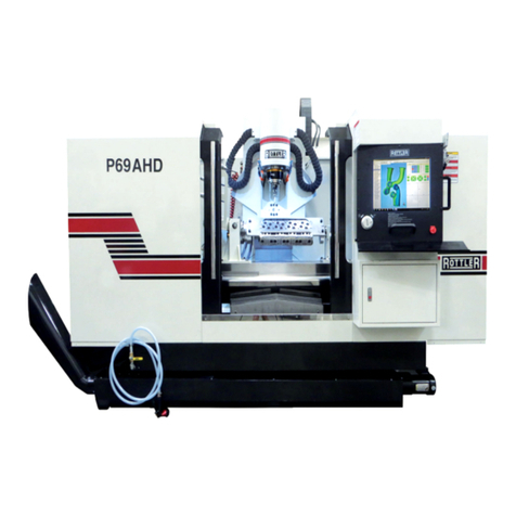
Rottler F103 Series User manual

OPERATION AND MAINTENANCE MANUAL
8029 S 200th St. Kent, WA 98032 USA | www.rottlermfg.com | Ph: 253-872-7050 | Fax: 253-395-0230
9.05.2019


ORDERING PROCEDURE
Contact your regional Rottler sales rep for assistance in ordering optional equipment, replacement parts,
or tooling.
If you are unable to contact your regional Rottler sales rep, call the factory at 253-872-7050 and ask to
speak to the parts sales specialist.
Have the following information handy to expedite the ordering process:
1. Your name, business name, and contact number
2. Customer number
3. If you don’t have a customer number, your billing address
4. Shipping address if different from billing address
5. Machine model and serial number
6. Part number and description of what you want to order
7. Preferred method of shipment
8. You may also contact us via e-mail with the above information. Send e-mail requests to:
In some cases you may be requested to send a photo of the part you are ordering if it is a replacement
part, or doesn’t appear in the database.
If you are unsure which part you need to order, contact our service department and ask to speak to one of
our service consultants. They will assist you in determining which part you require.
THERE IS A MINIMUM ORDER OF $25.00
MANUAL SECTIONS
INTRODUCTION
INSTALLATION
SAFETY
CONTROL DEFINITIONS
OPERATING INSTRUCTIONS
MAINTENANCE
TROUBLESHOOTING
MACHINE PARTS
OPTIONS
MSDS


Section 1 Introduction F103/4/5A Manual
www.rottlermfg.com
I
INTRODUCTION
Contents
Introduction..................................................................................................................1-1
Description...................................................................................................................1-2
Disclaimer ....................................................................................................................1-2
Limited Warranty .........................................................................................................1-3
Online Documentation Access...................................................................................1-4

Section 1 Introduction F103/4/5A Manual
www.rottlermfg.com
1-1
Introduction
READ THE SAFETY CHAPTER BEFORE INSTALLING MACHINE. THOROUGHLY UNDERSTAND
ALL SAFETY ISSUES BEFORE OPERATING MACHINE.
ATTENTION OWNER/BUSINESS MANAGER
To validate the warranty on your new Rottler machine, please
be sure to sign and complete the “Installation Report”
located in the Installation Chapter of this manual.
We suggest that the new user of the F103/4/5A read the CONTROL DEFINITIONS to get an idea how the
machine operates.
The Operating Instructions chapter should be read in order to familiarize the user with the actual button
pushing sequences required to carry out a job. These chapters in the manual should be considered an
introduction. As the operators of the F103/4/5A series machines gain experience with using the different
functions of the machine, complicated setups and programs will make more sense.
The rest of the manual contains information and part number reference on xtures, cutting tools, and
machine maintenance. The operator should read and become familiar with these areas as well.

Section 1 Introduction F103/4/5A Manual
www.rottlermfg.com
1-2
Description
The model F103/4/5A machine is a precision, single point boring, and high-speed surfacing unit. The
machine can be equipped with tooling and accessories for surfacing and re-boring most American
passenger car and truck engines, In-lines, as well as 90 and 60 degree V-types.
F103/4/5A machines can be easily tooled, to machine a wide range of engines, including European and
Asian engines, also, the machine can be easily adapted to perform other boring and surfacing operations.
The machine is designed, to maintain alignment of cylinder bores, and cylinder head, deck surfaces to the
pan rails and main bearing bore locations, as was done in the original factory machining. This overcomes
the many inaccuracies and out-of-alignment problems associated with clamping portable boring bars to
the cylinder head surface of blocks.
Convenient controls, fast block clamping, precise 3 axis CNC positioning and clamping, means
considerable savings in oor to oor time, and operator involvement.
Change over or resetting time required to set up V-type or in-line engines is a minimum, making this
machine highly suited to the jobber shop where engines cannot be run through in model lots.
All feeds and rapid travels are power operated and controlled form the control panel.
Disclaimer
The F103/4/5A Manual (henceforth to be referred to as the “Manual”) is proprietary to Rottler
Manufacturing LLC. (“Rottler Manufacturing”) and no ownership rights are hereby transferred. No part
of the Manual shall be used, reproduced, translated, converted, adapted, stored in a retrieval system,
communicated or transmitted by any means, for any commercial purpose, including without limitation,
sale, resale, license, rental or lease, without the prior express written consent of Rottler Manufacturing.
Rottler Manufacturing does not make any representations, warranties or guarantees, express or implied,
as to the accuracy or completeness of the Manual. Users must be aware that updates and amendments
will be made from time to time to the Manual. It is the user’s responsibility to determine whether there
have been any such updates or amendments. Neither Rottler Manufacturing nor any of its directors,
ofcers, employees or agents shall not be liable in any manner whatsoever to any person for any loss,
damage, injury, liability, cost or expense of any nature, including without limitation incidental, special,
direct or consequential damages arising out of or in connection with the use of the Manual.
Rottler Manufacturing and its employees or representatives are not responsible for any information
regarding nal specications of any workpiece that is created as a nal product when using Rottler
equipment. It is the responsibility of the end user of Rottler equipment to determine the nal dimensions
and nishes of the workpiece that they are working on. Any information regarding nal dimensions and
nishes that appears in any Rottler literature or that is expressed by anyone representing Rottler is to
be regarded as general information to help with the demonstration of or for operator training of Rottler
equipment.

Section 1 Introduction F103/4/5A Manual
www.rottlermfg.com
1-3
Limited Warranty
The model F103/4/5A machine is a precision, single point boring, and high-speed surfacing unit. The
machine can be equipped with tooling and accessories for surfacing and re-boring most American
passenger car and truck engines, In-lines, as well as 90 and 60 degree V-types.
F103/4/5A machines can be easily tooled, to machine a wide range of engines, including European and
Asian engines, also, the machine can be easily adapted to perform other boring and surfacing operations.
The machine is designed, to maintain alignment of cylinder bores, and cylinder head, deck surfaces to the
pan rails and main bearing bore locations, as was done in the original factory machining. This overcomes
the many inaccuracies and out-of-alignment problems associated with clamping portable boring bars to
the cylinder head surface of blocks.
Convenient controls, fast block clamping, precise 3 axis CNC positioning and clamping, means
considerable savings in oor to oor time, and operator involvement.
Change over or resetting time required to set up V-type or in-line engines is a minimum, making this
machine highly suited to the jobber shop where engines cannot be run through in model lots.
All feeds and rapid travels are power operated and controlled form the control panel.
Disclaimer
The F103/4/5A Manual (henceforth to be referred to as the “Manual”) is proprietary to Rottler
Manufacturing LLC. (“Rottler Manufacturing”) and no ownership rights are hereby transferred. No part
of the Manual shall be used, reproduced, translated, converted, adapted, stored in a retrieval system,
communicated or transmitted by any means, for any commercial purpose, including without limitation,
sale, resale, license, rental or lease, without the prior express written consent of Rottler Manufacturing.
Rottler Manufacturing does not make any representations, warranties or guarantees, express or implied,
as to the accuracy or completeness of the Manual. Users must be aware that updates and amendments
will be made from time to time to the Manual. It is the user’s responsibility to determine whether there
have been any such updates or amendments. Neither Rottler Manufacturing nor any of its directors,
ofcers, employees or agents shall not be liable in any manner whatsoever to any person for any loss,
damage, injury, liability, cost or expense of any nature, including without limitation incidental, special,
direct or consequential damages arising out of or in connection with the use of the Manual.
Rottler Manufacturing and its employees or representatives are not responsible for any information
regarding nal specications of any workpiece that is created as a nal product when using Rottler
equipment. It is the responsibility of the end user of Rottler equipment to determine the nal dimensions
and nishes of the workpiece that they are working on. Any information regarding nal dimensions and
nishes that appears in any Rottler literature or that is expressed by anyone representing Rottler is to
be regarded as general information to help with the demonstration of or for operator training of Rottler
equipment.

Section 1 Introduction F103/4/5A Manual
www.rottlermfg.com
1-4
Online Documentation Access
Online documentation for machines and optional equipment can be accessed at the Rottler website. To
access documentation open your browser and navigate to https://www.rottlermfg.com.
Scroll to the bottom of the page and under the Owner Resources title click the type of documentation you
want to access.
If a log in window pops up asking for user name and password ll in the blanks as shown.

Section 1 Introduction F103/4/5A Manual
www.rottlermfg.com
1-5

Section 2 Installation F103/4/5A Manual
www.rottlermfg.com
I
INSTALLATION
Contents
F103/4/5 INSTALLATION PREPARATION REQUIREMENTS.....................................2-1
F100 SERIES INSTALLATION REPORT .....................................................................2-3
Removing Machine from Shipping Container.........................................................2-11
Installation Procedure...............................................................................................2-13
Rottler F103/4/5 Series Foundation and Hold Down Requirements ............................. 2-13
Lifting Machine with Provided Lift Eyes........................................................................... 2-14
F105A Hold Down and Jacking Bolt Locations ............................................................... 2-16
F105A Optional Enclosure Mounting Bolt Locations...................................................... 2-17
F104A Hold Down / Jacking Bolt Locations..................................................................... 2-18
F103A Hold Down / Jacking Bolt Locations..................................................................... 2-19
F103A Hold Down / Jacking Bolt Locations Sunken Foundation .................................. 2-20
F104A Hold Down / Jacking Bolt Locations Sunken Foundation .................................. 2-21
F105A Hold Down / Jacking Bolt Locations Sunken Foundation .................................. 2-22
F105A Hold Down / Jacking Bolt Locations Sunken Foundation .................................. 2-23
Machine Dimensions.......................................................................................................... 2-24
Location ...........................................................................................................................................2-25
Unpacking........................................................................................................................................2-25
Column Hold Down.........................................................................................................................2-25
Leveling ...........................................................................................................................................2-25
Air Supply............................................................................................................................ 2-26
Power Supply...................................................................................................................... 2-27
Grounding........................................................................................................................................2-27
Creating a Skype Account ........................................................................................2-28

Section 2 Installation F103/4/5A Manual
www.rottlermfg.com
2-1
F103/4/5 INSTALLATION PREPARATION REQUIREMENTS
1. Floor needs to be prepared with anchor bolts installed. Rottler highly recommends the Hilti system.
2. Machine needs to be set in place with a leveling pad under each leveling bolt. After setting the
machine in place, check that each anchor bolt nut turns freely and that there is no damage to the
anchor bolt threads.
3. Rough level the machine.
4. Electrical connection made to the machine. Provide 208-240 VAC 3 phase power. 60 amp service is
required.
5. Ground rod installed and connected.
6. 6. Air supply to the machine. Minimum 100 PSI of clean, dry air.
7. Fixtures removed from the machine bed, and cleaned of rust preventative.
8. Machine cleaned of rust preventative.
9. Machine requires an Internet connection. Preferably wireless.
10. Have a scrap block available for operator training. Preferably a block commonly repaired at your
facility.

Section 2 Installation F103/4/5A Manual
www.rottlermfg.com
2-2
ATTENTION OWNER/BUSINESS MANAGER
To validate the warranty on your new Rottler machine, please
be sure to sign the installation report after the installation
technician has installed the machine and veried the machine
is operating correctly and given the operators operation and
maintenance training.
Thank you for your cooperation and the opportunity to be of
service to you.
ROTTLER MANUFACTURING

INSTALLATION REPORT
REV 062718
F100 SERIES
OFFICE USE ONLY
Route to: Servicer Mgr Accounting Andy Accounting Warranty Exp Date ________
ROTTLER MANUFACTURING MUST HAVE THIS REPORT RETURNED
TO PROPERLY QUALIFY WARRANTY ON EQUIPMENT
Customer:____________________________ Address:_______________________________________
City:_________________________________ State:_____ Zip:_________ Phone:_______________
Country:______________________________
Machine Model:___________ Serial Number:__________ Representative:________________________
MACHINE INSTALLATION: Electrical information MUST be complete to validate this report.
______Customer has read and fully understands importance of machine location as explained in the
installation section of the manual.
The following is the customer’s responsibility prior to the arrival of Rottler
technician. Please initial each item when it is completed.
Customer must provide foundation and hold down bolt system, see following attached drawing
and document “F70 and F100 Series Foundation and Hold Down Requirements”
VERY IMPORTANT: Modern design machines contain electronic low voltage
circuitry that provides great advantages and a better machine life. BUT, you
must have an excellent, stable, isolated power supply along with an isolated
ground. If not, electrical noise problems are likely to interfere with machine
operation unexpectedly.
Customer is responsible for providing electricity to machine in a manner that meets the local
electrical code requirements.
______Remove machine from truck. Weight: F103 14,000 lbs (6,350 kg) F104 16,000 lbs (7257 kg) F105
18,000 lbs (8165 kg) F107 45,000 lbs (20,412 kg) F109 50,000 lbs (22680 kg).
______If the machine was shipped in a container follow the removal procedure in the installation section
of the manual. (F103, F104, F105 only)
______Remove xturing and misc. parts from machine and clean.
______Install machine on foundation with supplied jack pads under jacking bolts.
______Install hold down nuts and bolts, see attached document. – This must e done rst.
______Rough Level the machine using a precision level so there is equal tension on all bolts.
______This machine requires between 208 and 240 Volts AC, Three Phase, 50/60 Hz, isolated power
supply. For voltages above 240 or below 208 VAC, a 17kva transformer will be required and
is available at Rottler. Please specify voltage when ordering. Measure the incoming voltage
between L1 and L2, L2 and L3, and L1 and L3. Current requirements for this machine is 60 amps.
Measure the incoming AC voltage at least twice during installation.
1. L1to L2 __________VAC, L2 to L3 __________ VAC, L1 to L3 __________
2. L1to L2 __________VAC, L2 to L3 __________ VAC, L1 to L3 __________

Section 2 Installation F103/4/5A Manual
www.rottlermfg.com
2-4
______Measure each leg of the incoming supply to ground. Sometimes you may nd a “high” leg to
ground. When this happens make sure the high leg is running to L3.
L1 to ground __________VAC L2 to ground __________VAC L3 to ground __________VAC
Neutral and machine ground are not the same thing. You should measure an
open circuit between Neutral and ground.
IF VOLTAGE IS OUTSIDE THE CORRECT RANGE AT ANY TIME THE
MACHINE WILL NOT OPERATE PROPERLY AND MAY BE DAMAGED.
______Air of the proper pressure and capacity connected to the machine. Air supply must be free from oil
and water. Oil or water will damage electrical and air components.
______Customer should attempt to have junk work piece available.
______Have the operator read through the operation manual before training begins. This will help him
be familiar with the button pushing sequences. Have the operator read through the manual again
after training and some of the sequences will make more sense.
______Have Internet connection available for the machine. Either via Ethernet cable or Wireless. The
machine comes equipped with a wireless USB adapter.
The following is the Rottler technician’s responsibility
______Check column top and spindle base bottom for rust and nicks if spindle must be installed. Clean
and stone as required.
______When lifting spindle unit, keep in mind the front to back center of gravity is located approximately
12 inches from the front end and has a tendency to lean forward.
______Each main system is protected internally by circuit breakers. Green indicates the breaker is
“tripped” and red indicates the breaker is “Hot” (conducting electricity).
______Clean any rust inhibitor from the machine surfaces. Move the column from side to side continually
cleaning the machine base until all inhibitor is removed.
______Install spindle unit on column, if required, using one of the approved methods described in the
operation manual. (Spindle unit weighs 6,000 lbs, 2,800 Kgs.)
Using fork lift angle iron brackets
______Bolt brackets to each side of the spindle base.
______Use large C-clamps to clamp the fork lift forks to the angle iron brackets. This will prevent any
accidental slips. Loosen 1/2 13 x 3 1/2 Inch bolts on pendent arm to allow it to be moved out of
the way.
______Use a forklift to lift the spindle unit onto the column. Be careful to watch clearance of all items.
______Install the Right (Fixed Side Rail) and removable dowel pins. Torque Side Rail bolts to 80 Ft/lbs.
______Lift spindle unit into place. Push spindle base up against Right Side Rail.
______Install left side rail (9202A) with 2 Belleville’s (9024E) opposing each other () on each set screw
(9202D), torque side rail bolts to 80 Ft/lbs.
______Adjust the adjustable screws (9202D) on SIDE rails by tightening them until they bottom out, then
unscrewing them 1/8 turn.
______Measure the protrusion of the Sides Rails above the spindle base and record.
Right: Front _________ Rear _________
Left Front _________ Rear _________
______Install the Right and Left Top Rails.
______Install top rails (9202B) with 2 Belleville’s opposing each other () on each adjustable set screw
(9202D). Torque to 80 lbs.

Section 2 Installation F103/4/5A Manual
www.rottlermfg.com
2-5
______Adjust the adjustable screws (9202D) on TOP rails by tightening them until they bottom out, then
unscrewing them 3/4 turn.
______Remove angle iron brackets form spindle base.
______Connect air and oil lines per air logic diagram.
______Remind customer of the proper air pressure and capacity connected to the machine. Air supply
must be free from oil and water. Oil or water will damage electrical and air components.
______Connect electrical wires in main rear enclosure if required using machine wiring diagram.
MACHINE START-UP
When starting the machine for the rst time, it may move out of control. Make
sure all hands are clear of machine parts. Be ready to press the Emergency
Stop button if needed.
______BEFORE turning power on to the machine. Check all wires for security by using the correct screw
driver and turning CW until movement stops. Stranded wire can “spread” slightly from vibration
during transport.
______Install electrical component covers inside the electrical enclosure with fasteners provided.
______Turn main power on at the main disconnect switch located on the rear enclosure.
______If machine moves out of control, turn power off and contact factory for help in trouble shooting.
______If any of the circuit breakers “trip”, reset and call factory for possible trouble shooting.
______Install and test the Internet connection to the machine. DO NOT download any updates unless
instructed to do so by Rottler.
______Check the computer control options and make sure that you turn on z-axis bit 2 and spindle bit 3.
MACHINE MOVEMENTS
______Make sure there is nothing obstructing the full vertical, horizontal or In/Out travel of the machine
taking special notice of the rear enclosure, way travel and top of the spindle unit.
______Put the machine in hand wheel mode and verify Vertical operation. Put an indicator on the cutter
head and verify .001” movement per detent in course mode and .0001” in ne mode. If the
indicator is jumpy the outer spindle adjustment may be too tight. Refer to manual and re-adjust.
______Put the machine in hand wheel mode and verify Horizontal operation. Put an indicator on the
cutter head and verify .001” movement per detent in course mode and .0001” in ne mode
______Use the rapid buttons and verify proper vertical, horizontal and In/out travel.
______Check limit switch operation with handwheel before using the power feed.
______Move the machine to its vertical limits to verify proper operation.
______Move the machine to its horizontal limits to verify proper operation.
______Move the machine to its In/Out limits to verify proper operation.
______Start the spindle and verify operation at all speeds.
______Use the spindle creep buttons and verify proper operation.
______Prime the oiling system. (See maintenance section of manual for complete details.)
______Use a precision level and level the machine:
Record machine level readings below (must be within .0005). Back Way:
Back Way:
P1 ______ P2 ______ P3 ______ P4 ______ P5 ______ P6 _____ P7 _____ P8 _____
Back to Front Way:
P1 ______ P2 ______ P3 ______ P4 ______ P5 ______ P6 _____ P7 _____ P8 _____

Section 2 Installation F103/4/5A Manual
www.rottlermfg.com
2-6
Record Dial Indicator readings:
Spindle to Back Table:
P1 ______ P2 ______ P3 ______ P4 ______ P5 ______ P6 _____ P7 _____ P8 _____
Spindle to Front Table:
P1 ______ P2 ______ P3 ______ P4 ______ P5 ______ P6 _____ P7 _____ P8 _____
______Check mill tilt, and lift amounts with Y axis in the middle of travel, and record
Amount of tilt ____________ Amount of tilt _____________
(See Section 6 of the manual for specication)
The following procedures should be shown to personal involved in machine maintenance.
See maintenance section of manual for complete details. Video of procedure can be viewed at:
www.rottlertube.com
______Check, and adjust X axis gibs Should be .0002-.0005 (see maintenance for further instructions.)
______Adjust outer spindle bushings.
______Adjust inner spindle bearings
______Perform spindle sweep adjustment.
______Verify ALL axis backlash comp is operating properly, adjust if needed. Record actual readings after
verication.
Auto Handwheel
X-Axis__________ __________
Y-Axis__________ __________
Z-Axis__________ __________
______Install way cover brackets and way covers. Way Cover support brackets should be ush with way
surface.
INSTRUCTING THE OPERATOR
Note: Rotter employees and representatives per company policy are not permitted to provide end
user of Rottler equipment with any OEM specications for the workpiece that is created by end
user using Rottler equipment.
______ Explain to the customer and operator that at NO time is there to be any software or hardware
other than Windows Auto Update and Rottler installed on this machine. This includes screen
savers, anti-virus software, and any hardware device that installs software on the machine.
Installation of screen savers and anti-virus software can cause dangerous control problems. Any
installation of software or hardware will void the warranty on the machine.
______Explain to the customer and operator that the machine should be hooked up to the Internet
anytime it is on. The software on the machine will automatically connect to our server to send
back useful information on machine status.
______Connect customer supplied Internet to the machine. Verify that the Internet is accessible from the
machine.
______Once the machine has been fully setup and is ready for operation create a Skype account for the
machine following the instructions in the Installation Section of the manual.
______Explain to the customer and the operator how the to log onto Skype and communicate with Rottler
when needed.

Section 2 Installation F103/4/5A Manual
www.rottlermfg.com
2-7
______ Computer Viruses will cause the machine control system to become unstable. This may cause
the machine to make uncontrolled moves which could create a dangerous environment for the
machine operator.
______Refer to Chapter 4, Control Denitions of the Machine Manual, Section: Computer and Controller
System Safety. Explain and discuss this section carefully with Owner/Manager/Operator and have
them sign off. Failure to do so will result in the machine warranty being Null and Void.
_______________________________________________________________________
Signature / Title
______Explain to the customer the importance of backing up the block proles to a separate device. Any
computer failure or possible operator input error can result in the loss of all block proles that
were created for the machine. Refer to Chapter 5 of the machine manual for detailed instructions
on backing up and restoring block proles.
______Explain to the customer the proper way to turn the machine off when it is not in use. Do not
leave the machine on overnight. It is important to close all programs followed by shutting down
Windows before turning the main power switch off. Do not turn the main power switch off before
shutting down Windows.
______Using the operating manual as a guide explain the function of all buttons.
______Cycle all machine movements and supervise the handling of same by operator.
______Demonstrate the differences of Manual and Auto operation.
______Fully explain the entire Auto Cycle from Centering to Auto Retract.
______Explain machine parameters and error messages. It is very important that the customer does not
change parameter settings without rst checking with Rottler Manufacturing. If certain parameters
are changed the machine may make uncontrolled moves or not operate at all.
______Point out safety features to customer and operator. Do not push any buttons without thinking of
safety rst.
Do not assume the cutterhead micrometer has been calibrated.
______Install a work piece in the machine and perform an undersize test bore to qualify the micrometer
setting to the customers measuring tools.
Note adjustments: + __________, - __________.
______Explain precision reset of tool in cutterhead.
______The following is a checklist to go through every time the machine is started to begin a cut or
automatic cycle.
• Work piece secure
• RPM set
• Feed Rate set
• Correct program in use
• Program oriented correctly (vertical zero at correct place) Centering range adequate
• Guards in place
• Cutterhead secure
• Tool holder adjusted to the correct size
• Tool holder locked in place
______Proceed to have operator bore block to size.

Section 2 Installation F103/4/5A Manual
www.rottlermfg.com
2-8
______Demonstrate and explain boring with the electronic hand wheel.
______Explain the correct Feed rates and speeds from Cutting Insert Bulletin.
______Cutter head change and expected stub bar performance.
______Parts ordering, refer the to the operating manual for part numbers and description.
______Offset tool bits, calibration of micrometer and anvil setting.
______Train on ALL Rottler programs even if they need to be run in the air.
______If Rottler CAM was provided to the customer train on any programs supplied by Rottler.
______Review Emergency stop procedure with operator per operating manual.
MAINTENANCE SECTION
______Use the manual as a reference when explaining routine maintenance and lubrication.
______Overload devices, There are no mechanical overload devices on this machine. The machine is
protected from overload by the motor controllers. If the system is overloaded the controllers shut
the motors off. The controllers can be reset by turning the main power off for at least 1 minute,
then turning it back on.
______Explain again the proper Inner and Outer spindle adjustment to the operator.
______Dampener cleaning.
______Micrometer and anvil thread adjustment.
______Inspection of tool bit hole in tool holders (deformation due to accidental impact).

Section 2 Installation F103/4/5A Manual
www.rottlermfg.com
2-9
Rottler Manufacturing and its employees or representatives are not responsible for any information
regarding nal specications of any workpiece that is created as a nal product when using Rottler
equipment. It is the responsibility of the end user of Rottler equipment to determine the nal dimensions
and nishes of the workpiece that they are working on. Any information regarding nal dimensions and
nishes that appears in any Rottler literature or that is expressed by anyone representing Rottler is to
be regarded as general information to help with the demonstration of or for operator training of Rottler
equipment.
Note: Rotter employees and representatives per company policy are not permitted to provide end user of
Rottler equipment with any OEM specications for the workpiece that is created by end user using Rottler
equipment.
General remarks on machine performance, adjustments as received and any further organization or parts
required to complete the installation.
____________________________________________________________________________________
____________________________________________________________________________________
____________________________________________________________________________________
____________________________________________________________________________________
____________________________________________________________________________________
____________________________________________________________________________________
____________________________________________________________________________________
____________________________________________________________________________________
____________________________________________________________________________________
____________________________________________________________________________________
____________________________________________________________________________________
Instructions given to:___________________________________________________________________
Sales/Service Engineer: _______________________________________________ Date_____________
Shop Foreman/Superintendent or Owner: _________________________________ Date_____________
Once completed send this form to:
Rottler Manufacturing
attn: Service Manager
8029 S 200 St
Kent, WA 98032 USA
Alternately you may send this form via fax or e-mail:
fax: [+1] 253-395-0230
e-mail: [email protected]
This manual suits for next models
5
Table of contents
Other Rottler Control System manuals
Popular Control System manuals by other brands

Mitsubishi Heavy Industries
Mitsubishi Heavy Industries SC-SL1N-E Data book

MA lighting
MA lighting MA onPC user guide

Nordson
Nordson Encore HD iControl 2 Installation, troubleshooting, repair

BRULA
BRULA BRULA NEO Installation and service instructions

ADTRAN
ADTRAN Total Access 300 Series Installation and maintenance guide

Skov
Skov BlueControl Pig Technical manual