ADB Safegate RELIANCE Navigator User manual

ADB SAFEGATE RELIANCE Navigator™ Installation and Operation
Manual
Airport Lighting Control System
User Manual
96A0363, Rev. i, 2019/10/31


A.0 Disclaimer / Standard Warranty
CE certification
The equipment listed as CE certified means that the product complies with the essential requirements concerning safety and
hygiene. The directives that have been taken into consideration in the design are available on written request to ADB
SAFEGATE.
ETL certification
The equipment listed as ETL certified means that the product complies with the essential requirements concerning safety and
FAA Airfield regulations. The directives that have been taken into consideration in the design are available on written request
to ADB SAFEGATE.
LED Product Guarantee
Where applicable, per FAA EB67 (applicable edition), ADB SAFEGATE L858(L) Airfield Guidance Signs are warranted against
electrical defects in design or manufacture of the LED or LED specific circuitry for a period of 4 years. ADB SAFEGATE LED light
fixtures (with the exception of obstruction lighting) are warranted against mechanical and physical defects in design or
manufacture for a period of 12 months from date of installation; and are warranted against electrical defects in design or
manufacture of the LED or LED specific circuitry for a period of 4 years per FAA EB67 (applicable edition).
Note
See your sales order contract for a complete warranty description. In some specific cases, deviations are (to be)
accepted in the contract, which will supersede the standard warranty.
Standard Product Guarantee
Products of ADB SAFEGATE manufacture are guaranteed against mechanical, electrical, and physical defects (excluding lamps)
which may occur during proper and normal use for a period of one year from the date of installation or 2 years from date of
shipment and are guaranteed to be merchantable and fit for the ordinary purposes for which such products are made. ADB
SAFEGATE L858 Airfield Guidance Signs are warranted against mechanical and physical defects in design or manufacture for a
period of 2 years from date of installation per FAA AC 150/5345-44 (applicable edition).
Note
See your sales order contract for a complete warranty description.
All Products Guarantee
LED Products of ADB SAFEGATE, manufactured and sold by ADB SAFEGATE or its licensed representatives, meets the
corresponding requirements of FAA, ICAO and IEC.
ADB SAFEGATE will correct by repair or replacement per the applicable guarantee above, at its option, equipment or parts
which fail because of mechanical, electrical or physical defects, provided that the goods have been properly handled and
stored prior to installation, properly installed and properly operated after installation, and provided further that Buyer gives
ADB SAFEGATE written notice of such defects after delivery of the goods to Buyer. Refer to the Safety section for more
information on Material Handling Precautions and Storage precautions that must be followed.
ADB SAFEGATE reserves the right to examine goods upon which a claim is made. Said goods must be presented in the same
condition as when the defect therein was discovered. ADB SAFEGATE furthers reserves the right to require the return of such
goods to establish any claim.
ADB SAFEGATE’s obligation under this guarantee is limited to making repair or replacement within a reasonable time after
receipt of such written notice and does not include any other costs such as the cost of removal of defective part, installation
of repaired product, labor or consequential damages of any kind, the exclusive remedy being to require such new parts to be
furnished.
96A0363, Rev. i, 2019/10/31 iii
Copyright © ADB Safegate, All Rights Reserved
ADB SAFEGATE’s liability under no circumstances will exceed the contract price of goods claimed to be defective. Any returns
under this guarantee are to be on a transportation charges prepaid basis. For products not manufactured by, but sold by ADB
SAFEGATE, warranty is limited to that extended by the original manufacturer.
This is ADB SAFEGATE’s sole guarantee and warranty with respect to the goods; there are no express warranties or warranties
of fitness for any particular purpose or any implied warranties of fitness for any particular purpose or any implied warranties
other than those made expressly herein. All such warranties being expressly disclaimed.
Liability
WARNING
Use of the equipment in ways other than described in the catalogue leaflet and the manual may result in personal
injury, death, or property and equipment damage. Use this equipment only as described in the manual.
ADB SAFEGATE cannot be held responsible for injuries or damages resulting from non-standard, unintended uses of its
equipment. The equipment is designed and intended only for the purpose described in the manual. Uses not described in the
manual are considered unintended uses and may result in serious personal injury, death or property damage.
Unintended uses includes the following actions:
•Making changes to equipment that have not been recommended or described in this manual or using parts that are not
genuine ADB SAFEGATE replacement parts or accessories.
•Failing to make sure that auxiliary equipment complies with approval agency requirements, local codes, and all applicable
safety standards if not in contradiction with the general rules.
•Using materials or auxiliary equipment that are inappropriate or incompatible with your ADB SAFEGATE equipment.
•Allowing unskilled personnel to perform any task on or with the equipment.
© ADB SAFEGATE BVBA
This manual or parts thereof may not be reproduced, stored in a retrieval system, or transmitted, in any form or by any means,
electronic, mechanical, photocopying, recording, nor otherwise, without ADB SAFEGATE BVBA’s prior written consent.
This manual could contain technical inaccuracies or typographical errors. ADB SAFEGATE BVBA reserves the right to revise this
manual from time to time in the contents thereof without obligation of ADB SAFEGATE BVBA to notify any person of such
revision or change. Details and values given in this manual are average values and have been compiled with care. They are not
binding, however, and ADB SAFEGATE BVBA disclaims any liability for damages or detriments suffered as a result of reliance
on the information given herein or the use of products, processes or equipment to which this manual refers. No warranty is
made that the use of the information or of the products, processes or equipment to which this manual refers will not infringe
any third party’s patents or rights. The information given does not release the buyer from making their own experiments and
tests.
ADB SAFEGATE RELIANCE Navigator™ Installation and Operation Manual
iv
Copyright © ADB Safegate, All Rights Reserved

TABLE OF CONTENTS
1.0 Safety.........................................................................................................................................................................................1
1.1 Safety Messages.......................................................................................................................................................................................................... 1
1.1.1 Introduction to Safety...................................................................................................................................................................................2
1.1.2 Intended Use.................................................................................................................................................................................................... 2
1.1.3 Material Handling Precautions: Storage................................................................................................................................................ 3
1.1.4 Operation Safety.............................................................................................................................................................................................3
1.1.5 Maintenance Safety....................................................................................................................................................................................... 3
1.1.6 Material Handling Precautions, ESD........................................................................................................................................................4
2.0 ADB Safegate Navigator......................................................................................................................................................... 5
2.1 About this manual.......................................................................................................................................................................................................5
2.1.1 How to work with the manual................................................................................................................................................................... 5
2.2 ADB Safegate RELIANCE Navigator Airport Lighting Control System....................................................................................................5
2.2.1 Airport Lighting Control System...............................................................................................................................................................5
2.2.2 Terms and Abbreviation............................................................................................................................................................................... 8
2.2.3 Associated Drawings and Documents....................................................................................................................................................8
2.2.4 Components..................................................................................................................................................................................................... 9
2.2.5 Inspect Delivered Items..............................................................................................................................................................................10
3.0 Installation..............................................................................................................................................................................11
3.1 Mounting the Touchscreen................................................................................................................................................................................... 11
3.1.1 Flush Mount Touchscreen.........................................................................................................................................................................11
3.1.2 Desktop Stand-alone Touchscreen........................................................................................................................................................11
3.2 Mounting the Equipment...................................................................................................................................................................................... 11
3.3 Wiring Considerations.............................................................................................................................................................................................12
3.4 Connect the Computer...........................................................................................................................................................................................12
3.5 Wiring From CCRs.....................................................................................................................................................................................................13
3.5.1 Wiring from Controllable Element Monitoring Points (TB3 and TB4)......................................................................................13
3.5.2 Wiring for Controllable Element Points...............................................................................................................................................14
3.5.3 Wiring Notes for Separate B1/B10 Control........................................................................................................................................15
3.5.4 Watchdog Wiring......................................................................................................................................................................................... 15
3.5.5 Power Wiring (TB1)......................................................................................................................................................................................15
4.0 Operation................................................................................................................................................................................17
4.1 Starting the Touchscreen Program.....................................................................................................................................................................17
4.2 Overview of the Touchscreen...............................................................................................................................................................................18
4.3 Choosing a Page to View.......................................................................................................................................................................................19
4.4 Using the Control Buttons.....................................................................................................................................................................................19
4.4.1 Popup Style.....................................................................................................................................................................................................20
4.4.2 Push Button Style......................................................................................................................................................................................... 21
4.5 Using the Preset Buttons........................................................................................................................................................................................21
4.6 Using the Alarm Ack Button................................................................................................................................................................................. 23
4.6.1 Alarm Annunciation and Logging..........................................................................................................................................................24
4.6.2 Acknowledging an Alarm..........................................................................................................................................................................24
4.7 Using the Clean Screen Button............................................................................................................................................................................24
4.8 System Passwords.....................................................................................................................................................................................................26
4.9 Exiting Programs....................................................................................................................................................................................................... 26
5.0 Parts.........................................................................................................................................................................................29
A.0 SUPPORT................................................................................................................................................................................ 31
A.1 ADB SAFEGATE website..........................................................................................................................................................................................31
A.2 Recycling......................................................................................................................................................................................................................32
A.2.1 Local authority recycling...........................................................................................................................................................................32
A.2.2 ADB SAFEGATE recycling.......................................................................................................................................................................... 32
96A0363, Rev. i, 2019/10/31 v
Copyright © ADB Safegate, All Rights Reserved

ADB SAFEGATE RELIANCE Navigator™ Installation and Operation Manual
TABLE OF CONTENTS
vi
Copyright © ADB Safegate, All Rights Reserved
1.0 Safety
Introduction to Safety
This section contains general safety instructions for installing and using ADB SAFEGATE equipment. Some safety instructions
may not apply to the equipment in this manual. Task- and equipment-specific warnings are included in other sections of this
manual where appropriate.
1.1 Safety Messages
HAZARD Icons used in the manual
For all HAZARD symbols in use, see the Safety section. All symbols must comply with ISO and ANSI standards.
Carefully read and observe all safety instructions in this manual, which alert you to safety hazards and conditions that may
result in personal injury, death or property and equipment damage and are accompanied by the symbol shown below.
WARNING
Failure to observe a warning may result in personal injury, death or equipment damage.
DANGER - Risk of electrical shock or ARC FLASH
Disconnect equipment from line voltage. Failure to observe this warning may result in personal injury, death, or
equipment damage. ARC Flash may cause blindness, severe burns or death.
WARNING - Wear personal protective equipment
Failure to observe may result in serious injury.
WARNING - Do not touch
Failure to observe this warning may result in personal injury, death, or equipment damage.
CAUTION
Failure to observe a caution may result in equipment damage.
Qualified Personnel
Important Information
The term qualified personnel is defined here as individuals who thoroughly understand the equipment and its safe
operation, maintenance and repair. Qualified personnel are physically capable of performing the required tasks, familiar
with all relevant safety rules and regulations and have been trained to safely install, operate, maintain and repair the
equipment. It is the responsibility of the company operating this equipment to ensure that its personnel meet these
requirements.
Always use required personal protective equipment (PPE) and follow safe electrical work practice.
96A0363, Rev. i, 2019/10/31 1
Copyright © ADB Safegate, All Rights Reserved
1.1.1 Introduction to Safety
CAUTION
Unsafe Equipment Use
This equipment may contain electrostatic devices, hazardous voltages and sharp edges on components
• Read installation instructions in their entirety before starting installation.
• Become familiar with the general safety instructions in this section of the manual before installing,
operating, maintaining or repairing this equipment.
• Read and carefully follow the instructions throughout this manual for performing specific tasks and
working with specific equipment.
• Make this manual available to personnel installing, operating, maintaining or repairing this
equipment.
• Follow all applicable safety procedures required by your company, industry standards and
government or other regulatory agencies.
• Install all electrical connections to local code.
• Use only electrical wire of sufficient gauge and insulation to handle the rated current demand. All
wiring must meet local codes.
• Route electrical wiring along a protected path. Make sure they will not be damaged by moving
equipment.
• Protect components from damage, wear, and harsh environment conditions.
• Allow ample room for maintenance, panel accessibility, and cover removal.
• Protect equipment with safety devices as specified by applicable safety regulations
• If safety devices must be removed for installation, install them immediately after the work is
completed and check them for proper functioning prior to returning power to the circuit.
Failure to follow this instruction can result in serious injury or equipment damage
Additional Reference Materials
Important Information
•IEC - International Standards and Conformity Assessment for all electrical, electronic and related technologies.
•IEC 60364 - Electrical Installations in Buildings.
•FAA Advisory: AC 150/5340-26 (current edition), Maintenance of Airport Visual Aid Facilities.
•Maintenance personnel must refer to the maintenance procedure described in the ICAO Airport Services Manual,
Part 9.
•ANSI/NFPA 79, Electrical Standards for Metalworking Machine Tools.
•National and local electrical codes and standards.
1.1.2 Intended Use
CAUTION
Use this equipment as intended by the manufacturer
This equipment is designed to perform a specific function, do not use this equipment for other purposes
• Using this equipment in ways other than described in this manual may result in personal injury, death
or property and equipment damage. Use this equipment only as described in this manual.
Failure to follow this instruction can result in serious injury or equipment damage
ADB SAFEGATE RELIANCE Navigator™ Installation and Operation Manual
Safety
2
Copyright © ADB Safegate, All Rights Reserved

1.1.3 Material Handling Precautions: Storage
CAUTION
Improper Storage
Store this equipment properly
• If equipment is to be stored prior to installation, it must be protected from the weather and kept free
of condensation and dust.
Failure to follow this instruction can result in equipment damage
1.1.4 Operation Safety
CAUTION
Improper Operation
Do Not Operate this equipment other than as specified by the manufacturer
• Only qualified personnel, physically capable of operating the equipment and with no impairments in
their judgment or reaction times, should operate this equipment.
• Read all system component manuals before operating this equipment. A thorough understanding of
system components and their operation will help you operate the system safely and efficiently.
• Before starting this equipment, check all safety interlocks, fire-detection systems, and protective
devices such as panels and covers. Make sure all devices are fully functional. Do not operate the
system if these devices are not working properly. Do not deactivate or bypass automatic safety
interlocks or locked-out electrical disconnects or pneumatic valves.
• Protect equipment with safety devices as specified by applicable safety regulations.
• If safety devices must be removed for installation, install them immediately after the work is
completed and check them for proper functioning.
• Route electrical wiring along a protected path. Make sure they will not be damaged by moving
equipment.
• Never operate equipment with a known malfunction.
• Do not attempt to operate or service electrical equipment if standing water is present.
• Use this equipment only in the environments for which it is rated. Do not operate this equipment in
humid, flammable, or explosive environments unless it has been rated for safe operation in these
environments.
• Never touch exposed electrical connections on equipment while the power is ON.
Failure to follow these instructions can result in equipment damage
1.1.5 Maintenance Safety
DANGER
Electric Shock Hazard
This equipment may contain electrostatic devices
• Do not operate a system that contains malfunctioning components. If a component malfunctions,
turn the system OFF immediately.
• Disconnect and lock out electrical power.
• Allow only qualified personnel to make repairs. Repair or replace the malfunctioning component
according to instructions provided in its manual.
Failure to follow these instructions can result in death or equipment damage
96A0363, Rev. i, 2019/10/31 3
Copyright © ADB Safegate, All Rights Reserved
1.1.6 Material Handling Precautions, ESD
CAUTION
Electrostatic Sensitive Devices
This equipment may contain electrostatic devices
• Protect from electrostatic discharge.
• Electronic modules and components should be touched only when this is unavoidable e.g. soldering,
replacement.
• Before touching any component of the cabinet you shall bring your body to the same potential as the
cabinet by touching a conductive earthed part of the cabinet.
• Electronic modules or components must not be brought in contact with highly insulating materials
such as plastic sheets, synthetic fiber clothing. They must be laid down on conductive surfaces.
• The tip of the soldering iron must be grounded.
• Electronic modules and components must be stored and transported in conductive packing.
Failure to follow this instruction can result in equipment damage
ADB SAFEGATE RELIANCE Navigator™ Installation and Operation Manual
Safety
4
Copyright © ADB Safegate, All Rights Reserved
2.0 ADB Safegate Navigator
The scope of this manual is to assist you when installing and connecting the components of the NAVIGATOR™ Airfield
Lighting Control System.
The project specific contract / engineering drawings and instructions shall also be followed for information regarding
location, mounting requirements, fixing and connecting all components of the system.
2.1 About this manual
The manual shows the information necessary to:
Install and maintain the ADB Navigator™ system.
2.1.1 How to work with the manual
1. Become familiar with the structure and content.
2. Carry out the actions completely and in the given sequence.
2.2 ADB Safegate RELIANCE Navigator Airport Lighting Control System
The ADB Safegate RELIANCE Navigator™ Airport Lighting System represents the next generation of lighting control systems
specifically designed for airports that seek a cost-effective control and monitoring solution, such as general aviation airports
or military bases. Typically, this system can be used to replace hard-wired control desks and mimic panels (L-821/L-841 type)
providing basic control and monitoring of airfield ground lighting functions.
2.2.1 Airport Lighting Control System
Compliance with Standards
FAA: L-821 AC 150/5345-3 (Current Edition). ETL Certified.
ICAO: Annex 14, Vol. 1, para. 5.3 and 8.3 and Aerodrome Design Manual part 5, para. 3.4 and 3.7.
Military: UFC 3-535-01 par. 15-3.
System Overview
The ADB SAFEGATE RELIANCE Navigator Airport Lighting System represents the next generation of lighting control systems
specifically designed for airports that seek a cost-effective control and monitoring solution, such as general aviation airports
or military bases. Typically, this system can be used to replace hard-wired control desks and mimic panels (L-821/L-841 type)
providing basic control and monitoring of airfield ground lighting functions.
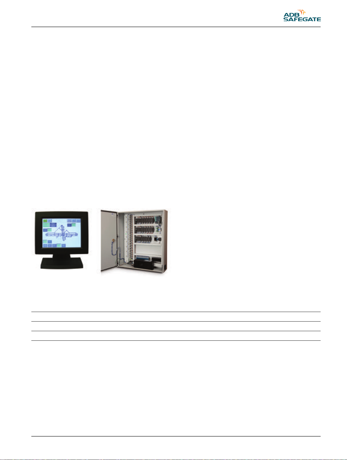
The standard ADB SAFEGATE Navigator system consists of one Touchscreen/ Panel PC and one PLC cabinet. It controls up to
18 airfield devices, such as CCRs, beacons, REILs, PAPIs, and floodlights. In addition, the Navigator has dedicated contact
points to monitor if utility and/or generator is available or on-line. If the airfield device is a CCR, there can be up to six 5-step
and twelve 3-step CCRs.
96A0363, Rev. i, 2019/10/31 5
Copyright © ADB Safegate, All Rights Reserved

Standard System Features
•Commissioning can be performed by the airport's technical staff (“out-of-the-box”), simplifying system delivery and setup
on site. ADB SAFEGATE support available if needed.
•The lighting control system is built around an integrated Touchscreen/Panel PC, requiring only minimal installation space
in the ATC tower. It incorporates a Human Machine Interface (HMI) with control functionalities for approach, runway,
taxiway and apron visual aids.
•High-contrast, anti-glare resistive 12-inch LCD Touchscreen. Standard Touchscreen can be either pedestal or flush mount.
•Intuitive user interface provides buttons that lead air traffic controllers through lighting control tasks
•The ADB SAFEGATE Navigator can be remotely controlled using an L-854 Radio Control, photocell or phone dial-in device
•A static airfield touchscreen graphic (.png file) can be added
•Provides visual alarm indications for all monitored points
•Soft-start CCR control provides programmable delays between intensity step switching
•Based on Windows™ Embedded Standard 2009
•Entire system uses only off-the-shelf components
•Highly reliable and effective PLC-based control and monitoring of CCRs and auxiliary circuits
•If the controllable item is a CCR, each CCR can have up to 3 dedicated feedback contact points (Primary Power; Remote/
Local status; CCR Output Current Sensing) or may have a single General Fault feedback point. A General Fault feedback
point is used, for example, to tie an FAA L-827/L-829 Fault indication into the system.
•Panel touchscreen has embedded PC with flash memory – no hard drive, fans or moving parts – limiting the need for
maintenance and providing a highly reliable control system
•PLC enclosure can be installed in either the tower (if space is available) or an electrical vault (standard 9 feet/3 m, or
optionally, up to 4,000 feet/1,219 m away) using EIA-485 communication
•Fail-safe – Fail-safe provides preset relays to meet airport operational requirements. Fail-safe is manually wired to select a
dedicated CCR step. Fail-safe can be manually overridden for maintenance troubleshooting purposes.
Hardware Options
•Second Touchscreen for tower or vault
•15-inch Touchscreen display
•Audible alarm speakers
•Communication methods: Fiber optic or wireless radio communication link
•CCR Monitoring Kit: Primary Power; Remote/Local and CCR ON Current Sensor
•UPS with UL1449 surge protection
•Remote dial-in capability (modem and software) for remote service and maintenance. A dedicated telephone line
(customer supplied) is connected to a modem that is added to the panel PC.
•L-854 radio remote control (see data sheet 3002)
•Phone dial-in device for password-protected lighting control
•Photocell (day vs. night input)
Operating Conditions
Operating Temperature: 0 °C (+32 °F) to +45 °C (+113 °F)
Extended Operating Temperature 1: -18 °C (0 °F) to +45 °C (+113 °F)
Relative Humidity: 10-95% at 40 °C (non-condensing)
Notes
ADB SAFEGATE RELIANCE Navigator™ Installation and Operation Manual
ADB Safegate Navigator
6
Copyright © ADB Safegate, All Rights Reserved

1Extended Operating Temperature available with the purchase of the Extreme Temperature Kit
Environmental Protection
Touchscreen Front Panel: NEMA 4 (IP 65)
PLC Cabinet: NEMA 4 (IP 65)
Electrical Supply
Touchscreen/Panel PC
Input power: Single phase, 100-240 VAC, 50/60 Hz
PLC Cabinet
Input power: Single phase, 100-264 VAC, 50/60 Hz
Dimensions
12″ Touchscreen/Panel PC with Stand (H × W × D)
10.6 × 13.41 × 2.78 – in (26.9 × 34.06 × 7.06 – cm)
15″ Touchscreen/Panel PC with Stand (H × W × D)
12.5 × 15.6 × 2.78 - in (31.76 × 39.65 × 7.06 - cm)
Stainless Steel Enclosure (H × W × D)
41.75 × 35.75 × 10.75 – in (106.0 × 90.8 × 27.3 – cm)
Figure 1: Typical Preset Lighting Page (Shown with optional static graphic)
96A0363, Rev. i, 2019/10/31 7
Copyright © ADB Safegate, All Rights Reserved
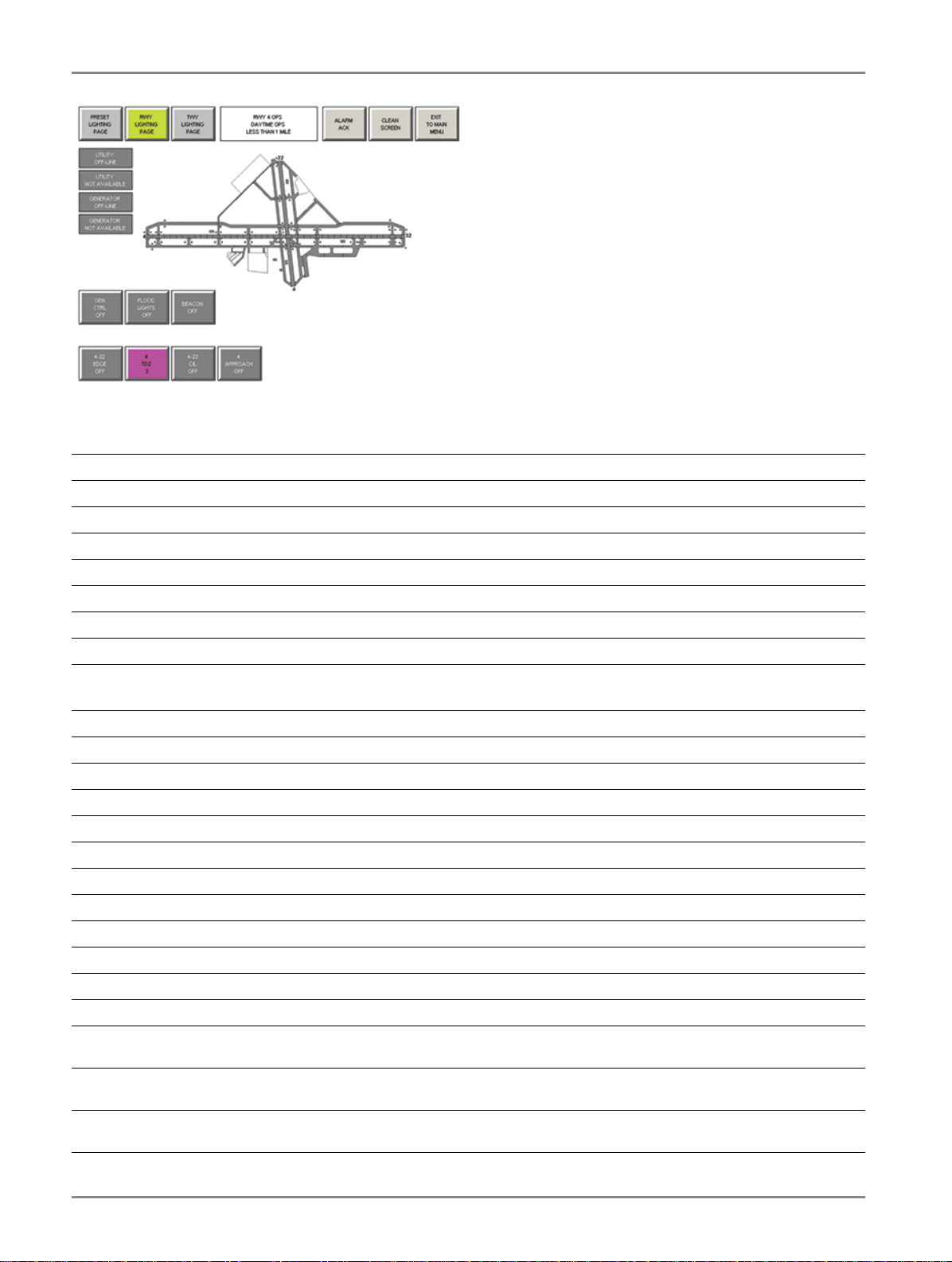
Figure 2: Typical Runway Lighting Page (Shown with “pop up” button configuration option)
2.2.2 Terms and Abbreviation
Term / Abbreviation Description
ALCS Airfield Lighting Control System
ALCMS Airfield Lighting Control and Monitoring System
ATC Air Traffic Control
ATCT Air Traffic Control Tower
PLC Programmable Logic Controller
HMI Human Machine Interface (i.e. Touchscreen)
CCR Constant Current Regulator
2.2.3 Associated Drawings and Documents
Document Number Description
43A4380-01 NAVIGATOR™ System Externals – Options
43A4380-02 NAVIGATOR™ System Externals – Local Communications
43A4380-03 NAVIGATOR™ System Externals – Fiber Optic Communications
43A4380-04 NAVIGATOR™ System Externals – Wireless Communications
105A0863 12.1" All-in-one touchscreen computer
105A0870/L157 15" All-in-one touchscreen computer
44A7675-01 PLC Enclosure Assembly Drawing
44A7675-02 PLC Enclosure Assembly Drawing
43A4582-01 Vault Enclosure Assembly Internal Wiring Diagram Drawing
43A4582-02 Vault Enclosure Assembly Internal Wiring Diagram Drawing
43A4582-03 Vault Enclosure Assembly Internal Wiring Diagram Drawing
43A4582-04 Vault Enclosure Assembly External Wiring Diagram Drawing- No
B1/B10
43A4582-05 Vault Enclosure Assembly External Wiring Diagram Drawing- No
B1/B10
43A4582-06 Vault Enclosure Assembly External Wiring Diagram Drawing- No
B1/B10
ADB SAFEGATE RELIANCE Navigator™ Installation and Operation Manual
ADB Safegate Navigator
8
Copyright © ADB Safegate, All Rights Reserved
Document Number Description
43A4582-07 Typical CCR Wiring Diagram Drawing- No B1/B10
43A4582-08 Vault Enclosure Assembly External Wiring Diagram Drawing-Separate
B1/B10
43A4582-09 Vault Enclosure Assembly External Wiring Diagram Drawing-
Separate B1/B10
43A4582-10 Vault Enclosure Assembly External Wiring Diagram Drawing-
Separate B1/B10
43A4582-11 Typical CCR Wiring Diagram - Separate B1/B10
43A4582-12 Vault Enclosure Assembly Internal Wiring Diagram Drawing- Power
and Comm
43A4582-13 Watchdog Timer Internal Wiring Diagram
44A7676-X Fiber Optic Communication Enclosure
43A4583-01 Fiber Optic Communication Enclosure Internal Wiring Diagram
44A7677 K2-4G #2 Wireless Radio Communication Enclosure
144A2440-XX 2.4 GHz Yagi antenna and grounding assembly
94A0454-DC DC Current Sensing Relay
Refer to the ADB Safegate Web site at www.adbsafegate.com for a copy of these drawings, and additional information,
located in the Product Center.
2.2.4 Components
The RELIANCE NAVIGATOR comes with the following standard components:
•PLC cabinet
•ALL-in-One Touchscreen Computer with RELIANCE NAVIGATOR software installed
•Keyboard and mouse
•User guide
•Serial cable, 9 feet (3 m)
Other optional components may also be delivered with the system. These components may include:
•ALL-in-One Touchscreen Computer with RELIANCE NAVIGATOR software for a remote location
•Current sensing devices
96A0363, Rev. i, 2019/10/31 9
Copyright © ADB Safegate, All Rights Reserved

•Communication extension equipment
•UPS (Uninterruptible Power Supply)
Figure 3: Main components
2.2.5 Inspect Delivered Items
Inspect the carton and contents for any signs of damage. Notify ADB if any parts are missing or damaged.
ADB SAFEGATE RELIANCE Navigator™ Installation and Operation Manual
ADB Safegate Navigator
10
Copyright © ADB Safegate, All Rights Reserved

3.0 Installation
Before beginning installation:
•Determine where to place the PLC cabinet and touchscreen computer.
•Verify the cable run between the PLC cabinet and the computer, is within 9 feet (3 m) or construct an extension cable that
meets the requirements set forth in the print package. For a standard PLC cable extension, please refer to drawing
43A4380-02 for pin-out details.
•If the communication medium between the computer and the PLC cabinet is longer than 9ft. a communication extension
option may be purchased. These options include hardwire communication equipment with lightning protection, multi-
mode or single-mode fiber optic communication media converters, or 2.4 GHz serial radios. Refer to the print package for
equipment details.
•Ensure there is access for power and control wiring.
3.1 Mounting the Touchscreen
Touchscreens are available in either flush-mount or desktop stand-alone units. The standard version of the NAVIGATOR comes
with a 12” touchscreen computer that can be both flush mounted or mounted to a desktop stand.
3.1.1 Flush Mount Touchscreen
Determine where to mount the flush mount touchscreen in the ATCT.
•Make sure that there is ample space available around and below the mounting area. Please see the NAVIGATOR system
prints for dimensions. The 12” panel cutout dimensions can be found on drawing 105A0863. The optional 15” panel can
be found on drawing 105A0870/L157 (drawing 105A0870 for older installations).
•Cutout the console area to fit. Place the touchscreen down in the console making sure that the bezel catches on the
outside of the cutout for a flush fit.
•The power cord will be attached underneath the screen when it is mounted and should be plugged into critical power in
the ATCT.
•Refer to 105A0863 for specific touchscreen computer port connections. These will vary depending on the options
purchased so please take care in making these connections.
•All cabling going to the touchscreen should have adequate strain relief installed so that the cables and connections will
not be under any stress.
3.1.2 Desktop Stand-alone Touchscreen
Determine where the Stand-alone touchscreen is to be set up in the ATCT.
•Make sure there is a flat surface for the touchscreen to be set on to ensure stability.
•The power cord will be attached to the back of the monitor and must be plugged into critical power in the ATCT.
•Refer to 105A0863 for specific touchscreen computer port connections. These will vary depending on the options
purchased so please take care in making these connections.
3.2 Mounting the Equipment
The PLC cabinet must be installed indoors, protected from excessive heat, cold and dampness. The cabinet must be secured
to a structure that will support its weight (137lb. / 62kg). See cabinet specifications for details.
Provide adequate clearance around the cabinet for connecting control and power cables. Enough clearance must be left in
front of the cabinet to open the door safely for service.
See Drawing 44A7675-01 for dimensions, mounting details, and suggested mounting height.
96A0363, Rev. i, 2019/10/31 11
Copyright © ADB Safegate, All Rights Reserved
3.3 Wiring Considerations
The NAVIGATOR cabinet is wired at the factory and ready for power and monitoring connection by the installing contractor.
The cabinet requires these wiring connections:
•The computer must be linked to the cabinet with the supplied cable, extension cable, or communications package option.
•Constant Current Regulators and other airfield devices must be connected to the control and monitoring terminal blocks.
•External power must be supplied. A dedicated 15A circuit breaker.
•(at 120V AC) is recommended for providing power to the PLC cabinet or UPS depending on the power option purchased.
The installer must make conduit penetrations for cable entrances; the PLC cabinet has no knockouts. The cabinet penetrations
should be made at the bottom of the enclosure to avoid interference with any of the electrical components located within the
enclosure itself. If a communications extension cable is being used it is important to bring that cable into the PLC enclosure
via a separate conduit penetration to minimize possible interference problems.
The following sections provide general guidelines only. For all wiring, refer to Installation Drawings (see Associated Drawings
and Documents).
3.4 Connect the Computer
The airport is to supply the CAT5 cable from the PC to the PLC.
•In the standard system that does not include any communication extension equipment, simply connect the CAT5 cable to
the network port on the back of the touchscreen computer as shown in Figure 5.
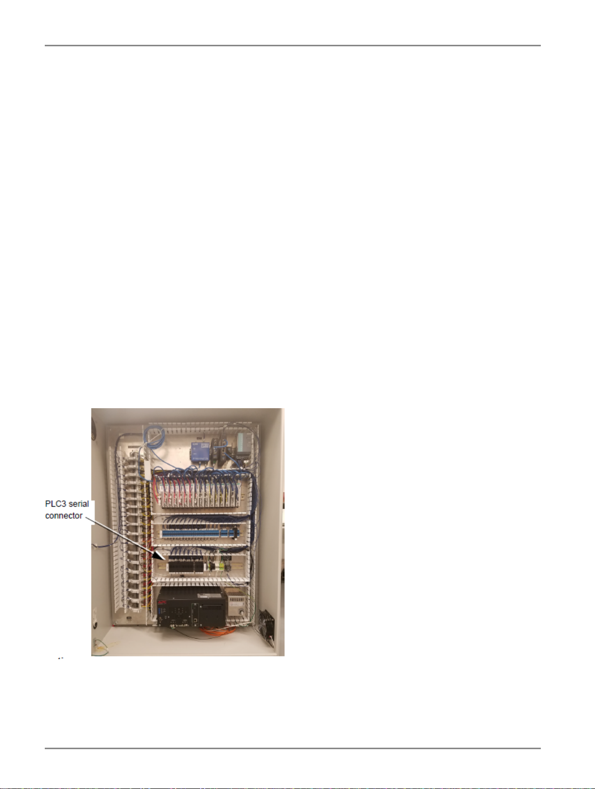
•Connect the other end to the network cable in the RELIANCE NAVIGATOR cabinet, as shown in Figure 4.
•For connection using communication extension equipment, please refer to the print package for connection details.
•Connect the power cord to the ATC critical power supply. Input Power to the computer should be 120 V AC (60 Hz) or220
V AC (50 Hz).
Figure 4: PLC Enclosure
ADB SAFEGATE RELIANCE Navigator™ Installation and Operation Manual
Installation
12
Copyright © ADB Safegate, All Rights Reserved

Figure 5: Touchscreen connections
3.5 Wiring From CCRs
CAUTION
•Failure to observe a caution may result in equipment damage.
•All power and control wiring must be performed by a qualified electrician. All power MUST be disconnected and
tagged out before beginning to make any wiring connections to the PLC cabinet and CCRs. For all wiring, refer to
Associated Drawings and Documents.
3.5.1 Wiring from Controllable Element Monitoring Points (TB3 and TB4)
Figure 6: Terminal Block locations
Alarm condition source voltage is supplied to each controllable element (Such as a CCR) from TB4 (labelled EXTERNAL DEVICE
24 VDC SOURCE). Each point on TB4 is fused so that the cabinet power supply is protected from an outside fault. The PLC
input modules are designed and pre-wired to actuate upon return of this alarm condition voltage. Hence it is required that
the source voltage be isolated from the controllable element power supply by an appropriate isolated contact such as relay
contacts or current sensing device contacts. If a relay is used, the coil of the relay is wired to the controllable element to
provide a contact
closure of the source voltage back to the PLC. CCR Current sensing/monitoring relay kits can be separately ordered from ADB
Airfield Solutions.
96A0363, Rev. i, 2019/10/31 13
Copyright © ADB Safegate, All Rights Reserved

TB3 (labeled CCR & MISC. MONITORING FEEDBACK) has 54 inputs—three for each controllable element—for monitoring
feedback.
All inputs to TB3 are rated for 24V DC only.
Table 1: Monitoring Connections
Function Connections
CCR #1 CCR #2
PP 1 4
RL 2 5
CO 3 6
The example above shows numbering for controllable elements 1 and 2.
One wire from each input may be connected to TB3 to monitor these points on the CCR along with each corresponding
common:
•Primary Power (PP)
•Remote/Local (RL)
•Commanded ON (CO)
Note
Note that any, all, or none of these inputs may be used. The conditions that will be used are configured during the
system configuration.
See Drawings 43A4582-05 and 43A4582-10 for monitoring point connections.
TB3 (labeled Remote Control IO) holds the connections for an L-854 Pilot Control Radio (PRC) and photocell, if used.
Depending on the type of radio or photocell that is being connected to the RELIANCE NAVIGATOR, an array of contact
closure relays will need to be added for the system to read these inputs correctly. If the PCR or photocell is a contact
closure, the relay can be sourced (24V DC) from the power block to the right of the remote control inputs. If the PCR or
photocell does not contain dry contact closures, the relays mentioned previously will need to be used. Do not use a 120V
AC control signal directly into TB3.
3.5.2 Wiring for Controllable Element Points
TB2 (labelled CONTROL) has 18 sets of terminal blocks; one set for each controllable element. The example at right shows
Terminal Block numbering for controllable CCR elements 1 and 2.
The first two connections in each group are dedicated to setting the preset fail-safe step for the CCR.
Table 2: CCR Connections and CCR Control Wiring (TB2)
Function
Separate B1 / no B1 required
Connections
CCR #1 CCR #2
Fail-safe 1-2 10-11
CCI 3 12
CC / CC (B1) 4 13
Step 1 (B1) / Step 2 (B2) 5 14
Step 2 (B2) / Step 3 (B3) 6 15
Step 3 (B3) / Step 4 (B4) 7 16
Step 4 (B4) / Step 5 (B5) 8 17
Step 5 (B5) / Not Used 9 18
ADB SAFEGATE RELIANCE Navigator™ Installation and Operation Manual
Installation
14
Copyright © ADB Safegate, All Rights Reserved
Table of contents
Other ADB Safegate Control System manuals


Popular Control System manuals by other brands

D+H
D+H CPS-M1-MSE-020 Series Original instructions

Philips
Philips dynalite installation guide

Dickey-John
Dickey-John Control Point Operator's manual

ABB
ABB Relion REC670 Operator's manual

Balboa Instruments
Balboa Instruments Poolux Installation and configuration manual

Johnson Controls
Johnson Controls YORK YLAA0189SE operating instructions


