Enerdrive DOMETIC EN31220 User manual

Owner’s Manual Rev: 5.4 (2021)
EN31220 - Charger 12V / 20Amp
EN31240 - Charger 12V / 40Amp
EN31260 - Charger 12V / 60Amp
EN32430 - Charger 24V / 30Amp
EN312100 - Charger 12V / 100Amp

Please Keep This Manual For Future Reference
For safe and optimum performance, the Enerdrive Battery Charger must be used properly.
Carefully read and follow all instructions and guidelines in this manual and give special attention to the
CAUTION and WARNING statements.
While every precaution has been taken to ensure the accuracy of the contents of this guide, Enerdrive
assumes no responsibility for errors or omissions. Note as well that specications and product functionality
may change without notice.
Please be sure to read and save the entire manual before using your Enerdrive Battery Charger.
Misuse may result in damage to the unit and/or cause harm or serious injury. Read manual in its
entirety before using the unit and save manual for future reference.
Battery Charger Owners Manual Rev. 5.4. This Manual is applicable to all units with serial number
prex EN.
Disclaimer
Important
Product Numbers - Battery Charger Series
EN31220 Battery Charger 12V / 20Amp
EN31240 Battery Charger 12V / 40Amp
EN31260 Battery Charger 12V / 60Amp
EN32430 Battery Charger 24V / 30Amp
EN312100 Battery Charger 12V / 100Amp
Service Contact Information
Dometic Power & Control (Enerdrive) Pty Ltd
PO Box 9159, Wynnum Plaza, QLD 4178
Ph: 1300851 535 / Fax: 073390 6911
Email: support@enerdrive.com.au | Web: www.enerdrive.com.au
Enerdrive Battery Charger Owners Manual Rev. 5.4Page 2

Enerdrive Battery Charger owner’s manual © 2021 Enerdrive. All rights reserved. No part of this
document may be reproduced in any form or disclosed to third parties without the express written
permission of Dometic Power & Control (Enerdrive) Pty Ltd. Enerdrive reserves the right to revise this
document and to periodically make changes to the content hereof without obligation or organisation
of such revisions or changes, unless required to do so by prior arrangement.
1. Unless specically agreed to in writing, Dometic Power & Control (Enerdrive) Pty Ltd: makes no
warranty as to the accuracy, suciency or suitability of any technical or other information
provided in its manuals or other documentation.
2. Assumes no responsibility or liability for losses, damages, costs or expenses, whether
special, direct, indirect, consequential or incidental, which might arise out of the use of such
information. The use of any such information will be entirely at the user’s risk.
3. Reminds you that if this manual is in any language other than English although steps have
been taken to maintain the accuracy ofthe translation, the accuracy cannot be guaranteed.
4. Makes no warranty, either expressed or implied, including but not limited to any implied
warranties of merchantability or tness for a particular purpose, regarding these Enerdrive
products and makes such Enerdrive products available solely on an “as is” basis.
5. Shall in no event be liable to anyone for special, collateral, incidental, or consequential
damages in connection with or arising out of purchase or use of these Enerdrive products.The
sole and exclusive liability to Enerdrive, regardless of the form of action, shall not exceed the
purchase price of the Enerdrive products described here in.
Notice of Copyright
Exclusions For Documentation And Product Usage
www.enerdrive.com.au Page 3

Page 4
Table of Contents
1. INTRODUCTION6
2. PRODUCT DESCRIPTION8
3. UNDERSTANDING THE UNIT9
Multistage Charging Process12
Smart Charging Feature 13
Battery Charger Voltage16
Battery Bank Size Recommendation16
4. INSTALLING THE CHARGER17
MountingThe Charger18
Chassis Grounding Connection19
DC OutputWiring19
Recommended Cable Length, Size And Required Fuse Size 19
Standard Temperature Sensor Connection20
OptionalRemote Display Connection20
RunningThe Battery Charger With Portable Generators 21
Battery Wiring: Connecting The Batteries The Right Way 22
5. UNIT OPERATION24
UnderstandingThe Charging Mechanism24
For Charging GEL, AGM And Flooded Batteries24
For Charging Lithium Batteries25
Enerdrive Battery Charger Owners Manual Rev. 5.4

For Using Charger As Power Supply (Program Setting)25
UnderstandingThe Display And Function Keys During Normal Operation 26
UnderstandingThe Function Key‘MENU’,‘SET’And‘SEL’During Charger Setting26
UnderstandingThe Three-Stage (Mode 3) Charging26
UnderstandingThe Two-Stage (Mode 2) Charging26
UnderstandingThe Battery Temperature Functions27
Procedure To Set Or View Charger Setting28
GEL, AGM Or Flooded Battery Type:28
Lithium Battery Type29
Program (Power Supply) Type30
Procedure To Equalize Flooded Battery 30
UnderstandingThe Silent Mode Function32
UnderstandingThe Protection Features 33
Charging A Dead Battery 33
UnderstandingThe Error Codes34
6. SPECIFICATIONS35
7. WARRANTY 37
5 Year Warranty 37
8. Appendix 136
9. Appendix 238
www.enerdrive.com.au Page 5

1. INTRODUCTION
IMPORTANT SAFETY INFORMATION
CAUTION
FIRE AND/OR CHEMICAL BURN HAZARD
Do not cover or obstruct any air vent openings and/or install in a zero-clearance compartment.
WARNING
SHOCK HAZARD. KEEP AWAY FROM CHILDREN!
Avoid moisture ingress. Never expose the unit to snow, water, etc.
Page 6 Enerdrive Battery Charger Owners Manual Rev. 5.4
Thank you for purchasing the Enerdrive Battery Charger. With our state of the art, easy to use design, this
product will oer you reliable service for providing a multistage, multi-bank battery charger to charge
the dierent types of batteries you have installed in either your home, boat, caravan, 4WD or commercial
vehicle. This manual will explain how to use this unit safely and eectively. Please read and follow these
instructions and precautions carefully.
This section contains important safety information for the Enerdrive Battery Charger.
Each time, before using the Enerdrive Battery Charger, READ ALL instructions and cautionary markings on
or provided with the Battery Charger, and all appropriate sections of this guide. The Enerdrive Battery
Charger contains no user serviceable parts. Opening up the charger will void product warranty.
See warranty section for how to handle product issues.

WARNING
FAILURE TO FOLLOW THESE INSTRUCTIONS CAN RESULT
IN DEATH OR SERIOUS INJURY
www.enerdrive.com.au Page 7
When working with electrical equipment or batteries, have someone nearby in case of an
emergency.
Study and follow all the battery manufacturer’s specic precautions when installing, using and
servicing the battery connected to the charger.
Wear eye protection and gloves.
Avoid touching your eyes while using this unit.
Keep fresh water and soap on hand in the event battery acid comes in contact with eyes. If this
occurs, cleanse right away with soap and water for a minimum of 15 minutes and seek medical
attention.
Lead Acid Batteries produce explosive gases. DO NOT smoke or have an open spark or re near the
system.
Never attempt to re-charge a damaged, frozen or non-rechargable battery.
Keep unit away from moist or damp areas.
Avoid dropping any metal tool or object on the battery. Doing so could create a spark or short circuit
which goes through the battery or another electrical tool that may create an explosion.
Battery charger must be plugged in to an earthed and Australian Standards compliant outlet.
If the unit’s power cable is damaged, replace the cable immediately.

WARNING
LIMITATIONS OF USE
Page 8
2. PRODUCT DESCRIPTION
The Enerdrive Battery Charger package includes the items listed below:
•Battery Charger
•Battery Temperature Sensor (7.5 Meter Cable)
•IEC 240Vac Power Lead
•Owner’s manual (Rev: 5.4) September 2021
• Appendix A1 rev 3 (see page 36 & 37 of this manual)
•Appendix A2 rev 3 (see page 39 & 39 of this manual)
Enerdrive Battery Charger Owners Manual Rev. 5.4
DO NOT use the Enerdrive Battery Charger in the vicinity of ammable fumes or gases (such as gas
bottles or large engines).
AVOID covering the ventilation openings. Always operate unit in an open and well ventilated area.
Prolonged contact to high heat or freezing temperatures will decrease the working life of the unit.
Do not use in connection with life support systems or other medical equipment or devices.
Charger is not to be used by persons with reduced physical or mental capabilities or lack of
knowledge and experience. Not to be operated or used by children.

www.enerdrive.com.au Page 9
3. UNDERSTANDING THE UNIT
The Enerdrive Battery Charger is a fully automatic multistage battery charger with the ability to charge
three separate battery banks.
When rst connected to an AC power source, the charger will check all three battery banks before
charging commences. The Battery Charger operates on an isolated charging design where battery bank
one is separate from battery bank two and three. Battery bank one is the priority battery bank in the
charging sequence and must be connected to the primary house (or main) battery bank. Battery bank
one can be programmed with a dierent charge algorithm over banks two and three.
Battery bank two and three are connected in parallel internally (with a separation diode) and share a
common charge algorithm.
During normal operation the Battery Charger will do a full charge cycle to oat stage on battery bank one
with battery types set to either GEL, AGM, FLOODED or LITHIUM (see Lithium section for limitations of
use). Once oat stage is reached the charger transitions to charge banks two and three together with a
bulk / absorption mode (battery banks two and three can be set to either GEL, AGM or FLOODED). The
EN312100 allows for Lithium Batteries to be charged from all three outputs.
On completion all three battery banks move to oat stage with a shared battery voltage determined by
bank one settings. This setting allows the charger to remain permanently connected to mains if required.
CAUTION
Battery bank one should ONLY be connected to the main battery bank that requires charge priority.
On single battery bank installations DO NOT use bank two and three charger outlets.
Page 10
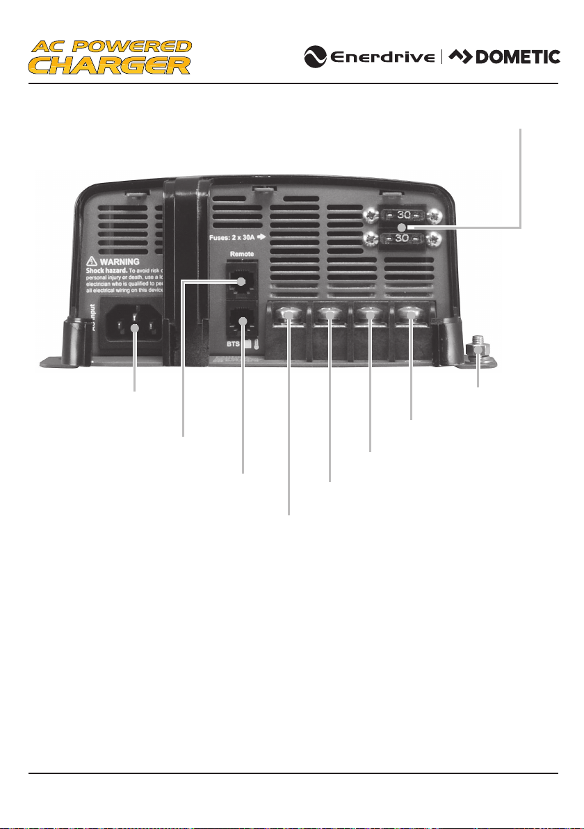
AC Power Cable
Input
BTS (Battery Temperature Sensor) Port
Remote Display Port Battery Positive Bank 3
Battery Positive Bank 2
Battery Positive Bank 1
Battery Negative Common
DC Output fuses
Unit Ground
Enerdrive Battery Charger Owners Manual Rev. 5.4
EN31220, EN31240, EN31260, EN32430
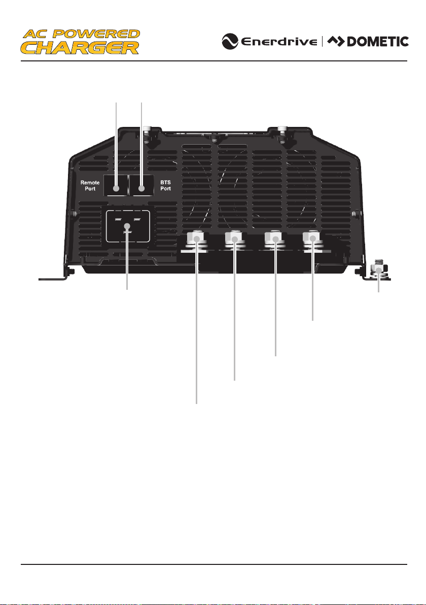
Remote
Port Display
AC Power
Cable Input
Battery Positive Bank 1
Battery Positive Bank 2
Battery Positive Bank 3
Battery Negative Common
Unit Ground
BTS (Battery Temperature Sensor)
Port
www.enerdrive.com.au Page 11
EN312100

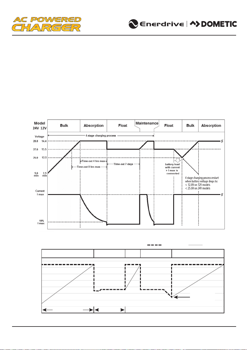
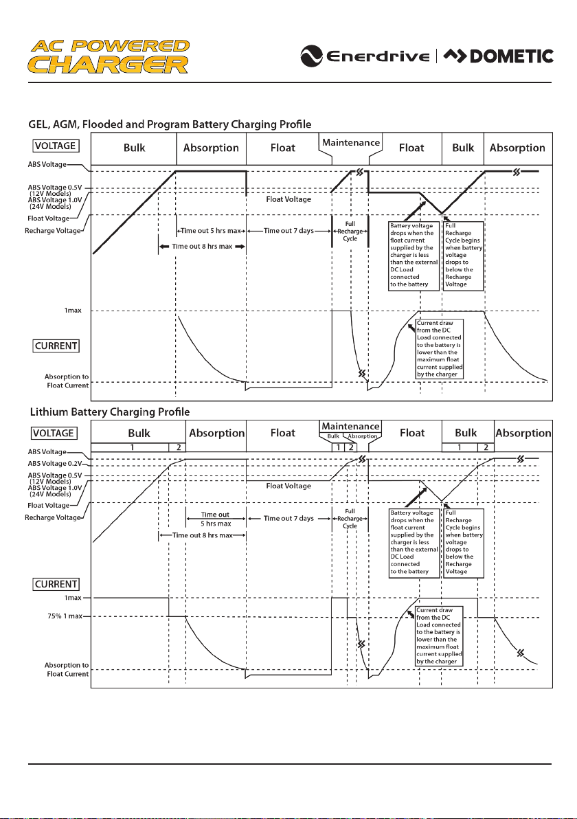
Multistage Charging Process for Lead Acid Batteries
The Battery Charger is a fully automatic, set and forget charger. It is designed to quickly and accurately
recharge your deep cycle batteries utilising charger algorithms that help to maximise the life of your
specialised deep cycle batteries.
These Battery Chargers feature multistage smart charging technology that enables the charger to be
connected to your battery banks permanently.
The Battery Charger utilise high frequency power switching circuits to convert the normal mains 240 volts
AC (via either shore or generator power), to the required low voltage DC required to charge the batteries.
As dictated by battery manufacturer’s recommendations, deep cycle batteries require a multistage charge
sequence for perfect, fast and accurate charging. Enerdrive multistage smart chargers delivers four
primary charge stages.
Stage 1 – Bulk or Boost charge; The battery is charged at full rated output current of the charger until
the battery reaches its nal charging voltage, known as its absorption voltage. In this step, around 80%
of the battery is recovered as fast as possible.
Stage 2 – Absorption Charge; With the charger voltage held steady, the remaining 20% is replaced with
the charger allowing the current to taper o as the battery approaches its full charge.
Stage 3 - Float, Finally, in the oat stage the charger voltage is lowered and held at a constant and safe
predetermined level. This prevents the battery from being overcharged, yet allows the charger to supply
enough current to make up for the self discharge losses of the battery, while supporting any additional
loads connected to the battery (such as DC lighting and refrigerators). This stage allows for the charger to
be used as a DC power supply.
Stage 4 - Maintenance stage is a regular timed recharge (or return to bulk stage). The Enerdrive Battery
Charger switches the charger from oat to boost after 7 days of constant operation to ensure the battery
banks remain active.
Page 12 Enerdrive Battery Charger Owners Manual Rev. 5.4
Smart Charging Feature
Battery Charger Algorithm
EN31220, EN31240, EN31260, EN32430
The Battery Charger will regulate its output based on the loads connected to your battery banks. This
function is important to maintain the life of your battery banks as some battery chargers mistake loads for
discharge and continue to keep the batteries in the bulk or absorption stage for extended periods of time,
which will damage the battery bank. The Battery Charger has two methods of load based regulation to
ensure your battery charger transitions to oat when it should do so.
www.enerdrive.com.au Page 13
Lithium Battery charging algorithm
14.4V
14.2V
14.0V
13.8V
13.6V
13.4V
13.2V
13.0V
12.8V
Battery Current
Bulk Float
Timeout8 hrs max Time out7days
Diagram does not illustrate our current set points.
Maint. Float Return to Bulk
Battery Voltage
13.2VDC triggers
Bulk Restart
Note: Actual voltages depend on chosen algorithm.
EN31220, EN31240, EN31260, EN32430
Page 14 Enerdrive Battery Charger Owners Manual Rev. 5.4
EN312100
Note: Actual voltages dependent on chosen algorithm.
In the event of AC mains loss the charger will react according to time without mains power.
Loss of AC power for less than 4 min - Charge resumes at existing stage.
Loss of AC power for more than 4 min - Charge resumes at bulk stage. See page 29 for Lithium settings.

www.enerdrive.com.au Page 15
Lead Acid Prole

Page 16
Battery Charger Voltage
Battery Type Absorption Float Equalisation
GEL 14.4 V 13.7 V N.A.
AGM 14.6 V 13.6 V N.A.
Flooded 14.4 V 13.3 V 15.5V (See Note1)
Lithium LiFeP04 Constant 13.9, 14.0, 14.1, 14.2, 14.3,
14.4, 14.5, 14.6 Volts (See Note2)N.A
Program (Power Supply) Constant 13.3, 13.5, 13.7 Volts (See Note3)N.A
* For 24V model charger multiply above voltages by 2.
** For Concorde™branded batteries (lifeline, sun x tender) use ooded setting and consult battery supplier for equalisation
recommendations
Note: Reference your Battery Manual for max charge current as this may dier
The battery charging current rating is based on the battery size. Each battery bank should meet the
minimum Ah rating as shown. If a smaller size battery bank is used, set the current rating to lower value
to match with the battery bank size. Normally, the minimum battery bank capacity is based on twice the
charger current rating.
EN31220 EN31240 EN31260 EN32430
Current
Setting
Battery
Capacity
Current
Setting
Battery
Capacity
Current
Setting
Battery
Capacity
Current
Setting
Battery
Capacity
5A Min 10Ah 5A Min 10Ah 5A Min 10Ah 5A Min 10Ah
10A Min 20Ah 10A Min 20Ah 20A Min 40Ah 10A Min 20Ah
15A Min 30Ah 20A Min 40Ah 40A Min 80Ah 20A Min 30Ah
20A Min 40Ah 40A Min 80Ah 60A Min 120Ah 30A Min 60Ah
Current
Setting
Battery
Capacity
Enerdrive Battery Charger Owners Manual Rev. 5.4
Note 1: Equalisation setting can only be used on ooded battery type selection only. See more details
on Procedure to Equalise the Flooded Battery.
Note 2: Charger will terminate charging when charging current drop to below the set charger
termination value (L setting).
Note 3: Charger is acting as a power supply with selected constant output voltage and preset maximum
output current. With this setting, only Bank 1 can be used, Bank 2 and 3 is disabled.
Battery Bank Size Recommendation
EN312100
40A Min 80Ah
60A Min 120Ah
80A Min 160Ah
100A Min 200Ah
www.enerdrive.com.au Page 17
4. INSTALLING THE CHARGER
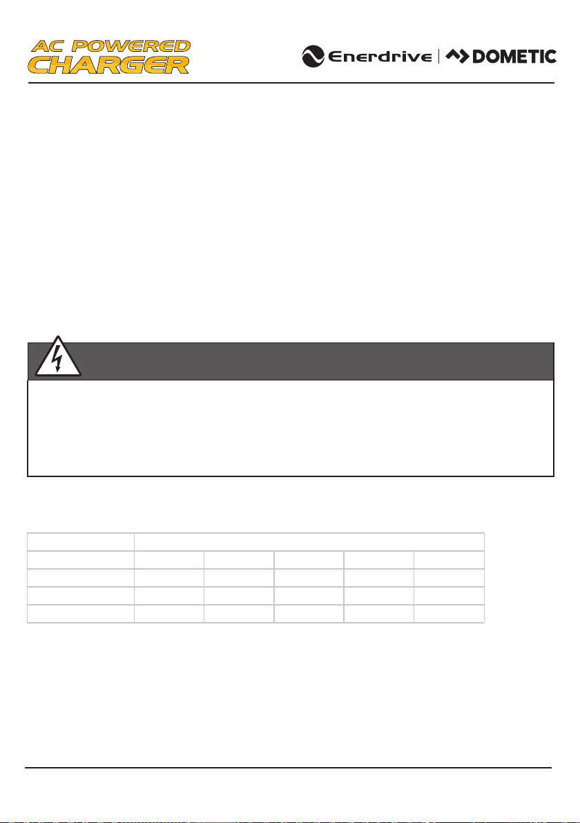
WARNING
Enerdrive recommends that all wiring be done by a skilled technician to ensure adherence to the best
practice standards for on-board DC electrical installations. Failure to follow these instructions can
damage the unit and could also result in personal injury or loss of life.
CAUTION
Before Beginning Your Unit Installation, Please Consider The Following:
The unit should be used or stored in an indoor area away from direct sunlight, heat, moisture or
conductive contaminants. This is an electronic device cooled by a fan and will prematurely fail if
installed in corrosive environments.
When placing the unit, allow a minimum of 75mm of space around the unit for optimal ventilation.
NOTE
The Enerdrive Battery Charger is designed to be permanently mounted.

Page 18 Enerdrive Battery Charger Owners Manual Rev. 5.4
EN312220 and EN31240 EN31260 and EN32430 EN312100
Mounting The Charger
•Choose an appropriate mounting location.
•For installing in an indoor location, the unit can be mounted in any direction although mounting the
charger vertically provides the best thermal performance.
•
•
•
For installing in boat or marine environment, the unit can be mounted horizontally and vertically (AC
and DC panel facing downwards only) to provide adequate drip protection.
Use the base of the charger as a mounting template to mark the positions of the xing screws.
Drill the 4 xing holes and place the charger in position and fasten the unit to the mounting surface.
220 mm
275 mm
73 mm
73 mm
88 mm
www.enerdrive.com.au Page 19
Chassis Grounding Connection
DC Output Wiring
Recommended Cable Length, Size And Required Fuse Size
Wire Length Wire Size (mm2) - Fuse Size (A)
Model EN31220 EN31240 EN31260EN32430
1.5 m 6mm2– 30A 12mm2– 50A16mm2– 80A12mm2– 40A
2.2m 6mm2– 30A 16mm2– 50A25mm2– 80A16mm2– 40A
6m (Not Recommended)16mm2– 30A 35mm2– 50A50mm2– 80A25mm2– 40A
2– 120A
2– 120A
EN312100
35mm
50mm
70mm2– 120A
WARNING: Correct DC Wiring is Required
The DC wiring used must be of appropriate size. An individual over-current protection device usually
within 20cm of each battery bank is required. A DC disconnect switch is also recommended. Both
devices must be rated for DC voltage and current and be rated to withstand the short circuit current
available from the connected battery bank. Both devices must match with the size of the DC wiring.
The unit is grounded through the ground stud located near the DC Output terminals, refer Section 3 on
Page 10 and 11.
For caravan, RV and other mobile applications the unit should be grounded with a minimum 4mm
conductor.
For marine applications the unit shall be grounded to the main DC negative bus with a separate
conductor the same capacity (size) as the DC positive conductor.
•
•

Page 20 Enerdrive Battery Charger Owners Manual Rev. 5.4
Remove the DC compartment cover by removing the two screws located on the top surface of the
unit near the AC wiring compartment.
Keep the connection between the battery and the charger as short as possible.
Connect one end of the positive wire (red wire) to the Bank one of charger positive terminal with
torque 4.0 ~ 5.0 N-m and the other end to the over current protection device, then the DC
disconnect device. Do not over tighten as this may result in damage to the charger.
Connect another wire from the DC disconnect device to the battery bank.
For systems with multi-battery banks: Follow the same instruction as on Bank 1 and connect to
Bank 2 & 3 accordingly.
Prepare the negative wire (black wire) and connect to the negative terminal of the charger.
Connect the other end of the negative wire to the negative terminal of the battery bank(s) or
the load side of a battery monitor shunt if installed.
Place the DC Compartment cover back to the original position and secure the cover using the two
screws provided.
To install the optional Remote Display in a specic location, a 6 pin standard RJ12 cable
(length of 7.5 meters supplied with Remote) is required.
Install the standard RJ12 cable in your desired location.
Connect one end of the RJ12 cable to the Interface Port and the other end of the cable to the
Display Panel.
The Remote Display is now ready for use.
Battery Temperature Sensor Connection
Optional Remote Display Connection
•
•
•
•
•
•
•
•
•
•
•
•
To install the temperature sensor, simply connect the RJ12 plug from the sensor to the RJ12 Temperature
Sensor Port located near the Interface Port. On the temperature sensor end, simply connect the ring
terminals to the negative terminal of the main battery bank.
This manual suits for next models
4
Table of contents
Other Enerdrive Batteries Charger manuals

Enerdrive
Enerdrive ePOWER Charger EN31220 User manual

Enerdrive
Enerdrive ePOWER DC2DC User manual

Enerdrive
Enerdrive ePower Industrial EPI-2430 User manual

Enerdrive
Enerdrive ePOWER DC2DC User manual

Enerdrive
Enerdrive ePower Industrial EPI-2430 User manual

Enerdrive
Enerdrive ePOWER Series User manual

Enerdrive
Enerdrive ePRO EPBC-1290 User manual
Popular Batteries Charger manuals by other brands


Quiet Power
Quiet Power QP100 Series Installation and operation manual

AL-KO
AL-KO B05-3640 Translation of the original instructions for use

Grape Solar
Grape Solar GS-600-KIT-MPPT Quick connect guide

VITO
VITO VICB16S instruction manual

ABB
ABB HT609440 Operation manual

ONE POINTECH
ONE POINTECH QB06 user manual


