Quiet Power QP100 Series User manual

!
!
!
!
!
!
!
!
"#$%&''&%()#!&#*!+,-.&%()#!/�&'!
!
10(-%!2)3-.!
40&'!567!89&.:-.!
!
12;<<!6-.(-$!
!
!
!
!
4)=0>-#%!2&.%!?0>@-.!ABCDA<<<E!
F-G($()#!H!I0#-!E<;J! !

Quiet Power USB Charger Installation and Operation Manual
P/N 98-790002 Rev 3 Page 2
TABLE OF CONTENTS
FKL"6"+?!M"6N+FO!PPPPPPPPPPPPPPPPPPPPPPPPPPPPPPPPPPPPPPPPPPPPPPPPPPPPPPPPPPPPPPPPPPPPPPPPPPPPPPPPPPPPPPPPPPPPPPPPPPPPPPPPPPPPPPPPPPPPPPPPPPPPPPPPPPPPPPPPPPPPPPP!Q!
;P!RK?KFST!4K68F"2N"+?!PPPPPPPPPPPPPPPPPPPPPPPPPPPPPPPPPPPPPPPPPPPPPPPPPPPPPPPPPPPPPPPPPPPPPPPPPPPPPPPPPPPPPPPPPPPPPPPPPPPPPPPPPPPPPPPPPPPPPPPPPPPPPPPP!J!
1.1!"#$%&'()$"&#!************************************************************************************************************************************************!+!
1.2!,-("./,#$!',0)%".$"&#!*********************************************************************************************************************************!+!
1.3!$,)1#")23!0.,)"4")2$"�!********************************************************************************************************************************!5!
1.3.1!!"#$%&'()*******************************************************************************************************************************************************)+!
1.3.2!,(-&./%&'()******************************************************************************************************************************************************)+!
1.4!262"3273,!/&',30!2#'!&.$"�!**********************************************************************************************************************!5!
EP!FKR5TSN+FO!8+/2T"S?8K!PPPPPPPPPPPPPPPPPPPPPPPPPPPPPPPPPPPPPPPPPPPPPPPPPPPPPPPPPPPPPPPPPPPPPPPPPPPPPPPPPPPPPPPPPPPPPPPPPPPPPPPPPPPPPPPPPPPPPPPPP!D!
HP!T"/"NSN"+?6!PPPPPPPPPPPPPPPPPPPPPPPPPPPPPPPPPPPPPPPPPPPPPPPPPPPPPPPPPPPPPPPPPPPPPPPPPPPPPPPPPPPPPPPPPPPPPPPPPPPPPPPPPPPPPPPPPPPPPPPPPPPPPPPPPPPPPPPPPPPPPPP!D!
QP!"?6NSTTSN"+?!2F+8K45FK6!PPPPPPPPPPPPPPPPPPPPPPPPPPPPPPPPPPPPPPPPPPPPPPPPPPPPPPPPPPPPPPPPPPPPPPPPPPPPPPPPPPPPPPPPPPPPPPPPPPPPPPPPPPPPPPPPPPPPPPP!D!
4.1!.32##"#8!******************************************************************************************************************************************************!9!
4.2!(#"$!"#0$2332$"&#!******************************************************************************************************************************************!:!
4.3!&.$"!2)),00&%",0!************************************************************************************************************************************!:!
4.3.1!012%(%'/#)3"'/4-/)!'5-()3655-&.6/)**************************************************************************************************************)7!
JP!4+85/K?NSN"+?!PPPPPPPPPPPPPPPPPPPPPPPPPPPPPPPPPPPPPPPPPPPPPPPPPPPPPPPPPPPPPPPPPPPPPPPPPPPPPPPPPPPPPPPPPPPPPPPPPPPPPPPPPPPPPPPPPPPPPPPPPPPPPPPPPPPPPPP!A!
5.1!"#0$%()$"�!4&%!)&#$"#(,'!2"%;&%$1"#,00!***************************************************************************************************!<!
5.2!3&87&&=!,#$%>!*******************************************************************************************************************************************!?@!
UP!2+6NC"?6NSTTSN"+?!NK6N6!PPPPPPPPPPPPPPPPPPPPPPPPPPPPPPPPPPPPPPPPPPPPPPPPPPPPPPPPPPPPPPPPPPPPPPPPPPPPPPPPPPPPPPPPPPPPPPPPPPPPPPPPPPPPPPPPPPPPPPPP!;;!
6.1!,/"!A!%4"!$,0$!.%&),'(%,!2#'!3&8!***************************************************************************************************************!??!
6.1.1!89:;<93;=<>)?%@)-A1%BB-CD)************************************************************************************************************************)EE!
6.1.2!F'/G-/)H-'&65)?%@)-A1%BB-CD)*********************************************************************************************************************)EE!
6.1.3!I!>)************************************************************************************************************************************************************)EJ!
6.1.4!8KL)36MM15%&'.%65$):-&-%N-/?$D)**************************************************************************************************************)EJ!
6.2!)&/.200!)1,)=!*******************************************************************************************************************************************!?B!
6.3!&.,%2$"!)1,)=0!************************************************************************************************************************************!?C!
DP!S22K?4"8K6!PPPPPPPPPPPPPPPPPPPPPPPPPPPPPPPPPPPPPPPPPPPPPPPPPPPPPPPPPPPPPPPPPPPPPPPPPPPPPPPPPPPPPPPPPPPPPPPPPPPPPPPPPPPPPPPPPPPPPPPPPPPPPPPPPPPPPPPPPPPPPP!;Q!
7.1!2..,#'"D!2!!,#6"%&#/,#$23!-(23"4")2$"&#!4&%/!******************************************************************************************!?E!
7.2!2..,#'"D!7!"#$,%)&##,)$!'"28%2/0!*************************************************************************************************************!?+!
7.3!2..,#'"D!)!/,)12#")23!'%2;"#80!***************************************************************************************************************!?5!
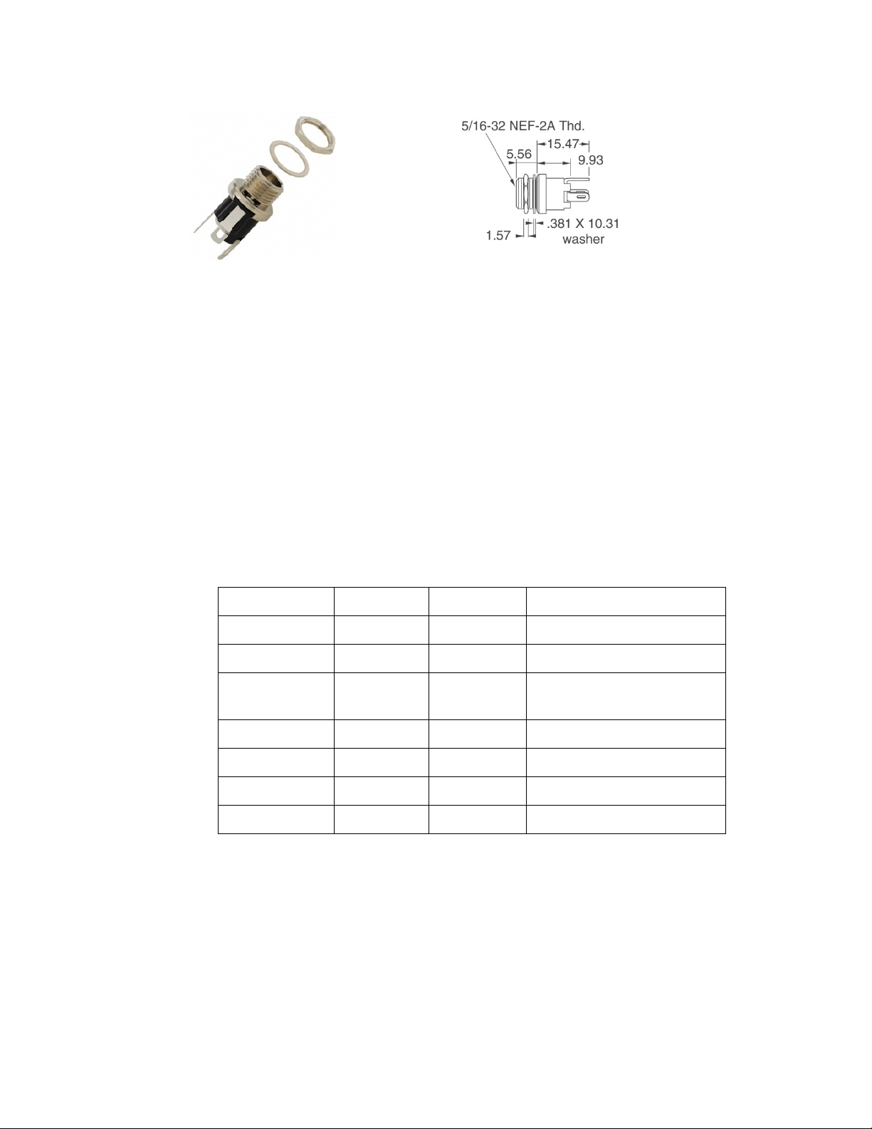
7.3.1!!'5-()31.61.O)P%/-&.)!'5-()F615.)*************************************************************************************************************)E+!
7.3.2!J)QR!'5-()F615.)0C'B.-/)!('.-)****************************************************************************************************************)E7!
7.3.3!S)TR)!'5-()F615.)0C'B.-/)!('.-)***************************************************************************************************************)EU!

Quiet Power USB Charger Installation and Operation Manual
P/N 98-790002 Rev 3 Page 3
COPYRIGHT NOTICE
Except as expressly provided herein, no part of this manual may be reproduced, copied,
transmitted, disseminated, downloaded or stored in any storage medium, for any purpose
without the express prior written consent of Summit Avionics or its’ subsidiary, Quiet
Power®. Summit Avionics hereby grants permission to download a single copy of this
manual and of any revision thereof onto an electronic storage medium to be viewed and
to print one copy, provided that such electronic or printed copy of this document must
contain the complete text of this copyright notice and provided, further, that any
unauthorized commercial use, distribution, or derivative of this manual or document is
strictly prohibited.
LIMITED WARRANTY
This product is warranted to be free from defects in materials or workmanship for two years from the date
of purchase. Within the applicable period, Quiet Power will, at its sole option, repair or replace any
components that fail in normal use. Repairs or replacement will be made at no charge to the customer for
parts or labor. The customer will be responsible for any transportation cost. This warranty does not apply
to: (i) damage caused by accident, abuse, misuse, water, flood, fire, or other acts of nature or external
causes; (ii) damage caused by service performed by another party; (iii) cosmetic damage, such as
scratches, nicks and dents; or (iv) damage to a product that has been modified or altered. Quiet Power
LLC and its parent, Summit Avionics, reserve the right to refuse warranty claims against products or
services that are obtained and/or used in contravention of the laws of any country. Quiet Power
exclusively retains the right to repair or replace (with a new, newly overhauled, or previously used
equivalent product ) the product or offer a refund of the purchase price at its sole discretion. SUCH
REMEDY WILL BE YOUR SOLE AND EXCLUSIVE REMEDY FOR ANY BREACH OF WARRANTY.
WARRANTIES AND REMEDIES CONTAINED HEREIN ARE EXCLUSIVE AND IN LIEU OF ALL OTHER
WARRANTIES, WHETHER EXPRESS, IMPLIED OR STATUTORY, INCLUDING ANY LIABILITY
ARISING UNDER ANY WARRANTY OF MERCHANTABILITY OR FITNESS FOR A PARTICULAR
PURPOSE, STATUTORY OR OTHERWISE. THIS WARRANTY GIVES YOU SPECIFIC LEGAL
RIGHTS, WHICH MAY VARY FROM STATE TO STATE.
IN NO EVENT WILL QUIET POWER LLC BE LIABLE FOR ANY INCIDENTAL, SPECIAL, INDIRECT OR
CONSEQUENTIAL DAMAGES, WHETHER RESULTING FROM THE USE, MISUSE OR INABILITY TO
USE THE PRODUCT OR FROM DEFECTS IN THE PRODUCT. SOME STATES DO NOT ALLOW THE
EXCLUSION OF INCIDENTAL OR CONSEQUENTIAL DAMAGES, SO THE ABOVE LIMITATIONS MAY
NOT APPLY TO YOU.
! !

Quiet Power USB Charger Installation and Operation Manual
P/N 98-790002 Rev 3 Page 4
!
FKL"6"+?!M"6N+FO!
Date
Revision
Description
7/24/2014
1
Original Release
7/30/2014
2
Corrected wiring reference in section 4
Added available models & options (Section 1.4)
1/7/2015
3
Added circuit breaker value table in Appendix B,
revised mechanical installation drawings to include
mounting with #4-40 or #6-32 screws. Added section
on backlighted models. Changed Series 1xx to 100
!

Quiet Power USB Charger Installation and Operation Manual
P/N 98-790002 Rev 3 Page 5
1. General Description
1.1 Introduction
This manual is intended to provide information pertinent to the
installation and operation of the Quiet Power converter /
charger. The product is designed to provide a reliable source
for charging devices through USB Type A plugs and,
optionally, charging remote electrical or electronic devices
through the auxiliary charger port.
Its signature “quiet” EMI / RFI ( Electro-Magnetic Interference /
Radio Frequency Interference ) characteristics permit it to be installed in many applications
that could be disturbed by EMI / RFI emissions from other similar devices.
1.2 Equipment Description
The Quiet Power line of USB chargers are engineered for use in aircraft cockpit or cabin
applications. They provide regulated, filtered D.C. power to common Portable Electronic
Devices (PED) to power these units during flight and charge their internal battery. Devices
that plug in to the USB connectors can draw a total of 3 amps. The QP unit signals the PED
that up to 2 amps are available on the top connector and 1 amp on the bottom connector. A
method referred to as ‘analog negotiation’ is used to signal the PED as to the available
power.
An optional auxiliary charging port is available on certain models of QP1xx chargers. This
port can supply 5, 9, 11, or 12 volts at 1 amp to a device to provide charging or auxiliary
charging current to that device. This port is typically used to power:
•Handheld radios with re-chargeable batteries
•Portable GPS receivers
•Portable standby / backup instrument systems
The auxiliary charger is intended to provide charging capabilities to those devices that might
be used intermittently and not otherwise receive a full charge. For example, connecting the
auxiliary charger to an emergency hand-held radio ensures that the radio is fully charged at
all times.
NOTE: The auxiliary charger is designed as a sacrificial device; if the USB chargers are
supplying full load and the temperature is very high the auxiliary charger will cycle on and off.
The Quiet Power unit is shipped in a container that includes the following materials:
•Installation and Operation Manual
•QP1xx Charging Device
•Power Cable / Wire Harness - ~6’ long
An optional connector kit is available from the manufacturer for the auxiliary charging port to
connect to common handheld devices.

Quiet Power USB Charger Installation and Operation Manual
P/N 98-790002 Rev 3 Page 6
1.2.1 Lighted Models
All of the QP100 series chargers are available with connector backlighting. These
units are ordered with a “-L” designator on the model number ( e.g. QP-104-L). The
backlighting is on continuously and projects a soft blue light within the USB
connector entrance. Intensity is adjusted at the factory for a subtle, low-intensity
light suitable for locating the charger connector in darkened cabin conditions.
1.3 Technical Specifications
1.3.1 Physical
The universal charger is housed in an aluminum enclosure.
Dimensions 1.83” high x 1.37” wide x 1.37” deep
Weight 3.5 oz.
1.3.2 Electrical
Input Voltage Range 10 volts to 36 volts D.C. (QP100 – QP102) or 13.2 to 36
volts D.C. ( QP103 – QP104)
Input Current 5 amps absolute maximum, 1 – 2.5 amps average at
rated load
Efficiency 87 to 93%
Output Characteristics
USB Top Port 2.1 amps at 4.8 to 5.2 volts
USB Bottom Port 1.1 amps at 4.8 to 5.2 volts
USB Negotiation Analog, Apple Products Standard
Auxiliary Output 1 amp at 5, 9, 11, or 12 volts factory preset
Nominal values shown
1.4 Available Models and Options
Quiet Power units are available in the following configurations:
Model
USB Port
Auxiliary Port
QP-100
Dual 5 VDC
None
QP-101
Dual 5 VDC
5 volts
QP-102
Dual 5 VDC
9 volts
QP-103
Dual 5 VDC
11 volts
QP-104
Dual 5 VDC
12 volts
Consult the installation and operations manual of your auxiliary device (hand-held radio etc.)
to confirm charging power requirements.

Quiet Power USB Charger Installation and Operation Manual
P/N 98-790002 Rev 3 Page 7
2. Regulatory Compliance
The QP1xx series products have been qualified to RTCA Standard DO-160G for
temperature, altitude, voltage spikes, power input, and radio frequency emissions /
interference for cockpit devices. The installing agency shall determine the regulatory basis
against which to install this device.
Installations have been performed as a Minor Alteration with appropriate logbook entry in
accordance with guidance provided by the FAA.
3. Limitations
None
4. Installation Procedures
4.1 Planning
The USB connector protrudes from the face of the unit approximately 0.14”. A standard
installation utilizes an aluminum instrument panel thickness of 0.060” to 0.090”. Should the
installation call for placement in a panel thicker than 0.14” or if it is desired to install the
device in a recessed area, care should be taken to determine the space required about the
perimeter of the USB connectors. Consider the PED devices that will be charged and allow
adequate clearance between the Quiet Power unit and adjacent equipment.
The USB connector requires a square hole through the instrument panel and two mounting
screw holes. Refer to Section 7.3 Appendix C Mechanical Drawings for detailed panel
information. You may also install the device in a standard 2 ¼” or 3 ⅛” instrument panel
opening using either an optional Quiet Power panel or a fabricated panel.
You may choose to install the Quiet Power device using either #6-32 screws or #4-40
screws. The #6-32 screws are aligned along the device vertical centerline and the #4-40
screws are adjacent to the connector. It is not necessary to install the device with more than
2 screws (i.e. two #6-32 or two #4-40).
If you select #4-40 mounting screws, choose the engagement length such that it will not
penetrate deeper than 0.330” / 8.2mm into the body of the Quiet Power unit. Minimum
engagement is 0.260” from the face of the unit to the end of the screw. The following table is
presented for reference.
Panel Thickness Screw Length Penetration Depth
0.060 / 1.5mm 0.375 / 9.3mm 0.315 / 7.9mm
0.090 / 2.3mm 0.375 / 9.3mm 0.285 / 7mm
Electrical installation of the unit requires a dedicated protective device, either circuit breaker
or fuse. Refer to Appendix B for sizing and wiring information. Installation shall be performed
using acceptable methods, practices, and techniques as specified in FAA Advisory Circular
43.13-1B and 43.13-2B.
Additional materials or special tools may be needed:

Quiet Power USB Charger Installation and Operation Manual
P/N 98-790002 Rev 3 Page 8
Mounting screws MS35206 (or equivalent),
Circuit protection device,
Wire MS22759 26-22 gauge (or equivalent),
Shrink tubing, lug connectors, soldering iron, heat gun
4.2 Unit Installation
Install the unit in the instrument panel by cutting or punching an opening in accordance with
Appendix C. Install the Quiet Power unit from the rear and secure with the chosen screws.
Wire the harness in to the aircraft electrical system per the diagram shown in Section 7.2
(Red wire to the protective device, White to aircraft ground). If the device is equipped with an
optional auxiliary charging capability, wire the additional two harness wires (black and white)
to the desired load or refer to Section 4.3.1 below. Plug the Quiet Power harness connector
into the Quiet Power unit.
Install a placard near the USB connector with the statement “5V 3A” or “Charging Port 5V
3A”.
4.3 Optional Accessories
4.3.1 Auxiliary Charger Panel Connector
The auxiliary charger port supplies power to the auxiliary device through an optional panel
connector and cable assembly. Power from the main power unit is supplied to the panel
connector from the cable assembly provided with the unit. A barrel power jack (5.5mm
OD, 2.5mm ID) is provided in the optional auxiliary charger kit (QPC-xxx below). If the
supplied power jack is used, the following instructions apply:
1. Prepare the wire harness by installing a 1” / 2.5mm heat-shrink sleeve over the
white and black wires after they have been trimmed to the appropriate length.
2. Solder the harness wires to the connector by connecting aircraft ground (white) to
the sleeve and power (black) to the pin. Do not make any connection to the sleeve
shunt terminal on the connector.
3. Slide the heat-shrink sleeve over the connector terminals / wire and heat / secure in
place.
4. Drill or punch a 0.33” / 8.4mm diameter hole in the panel. Panel thickness may be
up to 0.125” / 3mm.
5. Insert the connector through the panel and install the supplied washer and nut from
the front. Tighten the nut and make sure that the connector body is secure and will
not rotate.

Quiet Power USB Charger Installation and Operation Manual
P/N 98-790002 Rev 3 Page 9
Figure 1 - Charger Power Connector
Install a placard near the connector with one of the following statements, depending on
the model and auxiliary charger output voltage:
•“5 volts 1 amp”
•“9 volts 1 amp”
•“11 volts 1 amp”
•“12 volts 1 amp”
4.3.1.2 Connector-/-Cable-Kits-
The following Cable / Connector Kits are available from the manufacturer.
Each cable assembly includes a panel jack ( 5.5mm ID, 2.5mm Pin Dia.) and a 4’ /
1.3 M cable consisting of a mating panel plug, 4’ power cord and mating plug
(male) per the following table:
2&.%!?0>@-.!
/)*-'!
/&%(#:!2'0:!
6&>,'-!S,,'(=&%()#!
55F9<@@@C!!
-.)F@@?!
B*+D+*+!
!
55F9<@@@E!!
-.)F@@B!
B*?D+*+!
!
55F9<@@@+!!
-.)F@@C!
?*CDC*+!
")&/!25G!2BE!H!??!IJKL!A!-.F
?@CM!
55F9<@@@5!!
-.)F@@E!
?*9DE*@!
!
55F9<@@@9!!
-.)F@@+!
?*9DE*9+!
!
55F9<@@@:!!
-.)F@@5!
@*<DC*B!
!
55F9<@@@<!!
-.)F@@9!
C*CD+*+!
!
Order the optional connector / cable kit by Model. For updated Sample Application
information please visit the quietpower.aero website.
5. Documentation
5.1 Instructions for Continued Airworthiness
None required.
'NOPQRK!SPQNTUPJTU!UVJWT!PT!QNLXPO!YTPLU!

Quiet Power USB Charger Installation and Operation Manual
P/N 98-790002 Rev 3 Page 10
5.2 Logbook Entry
Complete an aircraft / airframe logbook entry detailing the installation and post installation
tests performed, Note the tests performed by referencing Section 6 Post-Installation Tests
(e.g. Tested to installation manual P/N 98-790002 Rev 2 Sections 6.2 (Compass) and 6.3
(Operational) – all tests normal ).
!

Quiet Power USB Charger Installation and Operation Manual
P/N 98-790002 Rev 3 Page 11
6. Post-Installation Tests
6.1 EMI / RFI Test Procedure and Log
After installation of the Quiet Power unit and confirmation of normal operation on aircraft battery
power, an EMI / RFI check may be performed in accordance with the following ground test
procedure. Note that this device has been qualified to DO-160G Section 21.0 Emission of Radio
Frequency Energy, Category M (Cockpit equipment). Consult AC 43.13-1B Section 8, Paragraph
11-107 or other regulatory guidance to confirm compliance with applicable regulations. Should the
installer determine that EMI / RFI testing is not required, notate the test log.
6.1.1 VOR/LOC/ILS (if equipped)
Verify normal operation of the Navigation receiver(s) and VOR indicator(s) and audio output
while tuning the receiver from 108.00 MHz to 117 MHz at 1 MHz increments. Turn the Quiet
Power unit off and on at 108.00, 112.00 and 116.00 and note whether any anomalies exist in
the VOR/LOC/ILS indicator or whether there is interference detected in the received audio.
Test
Interference /
Anomalies
Yes / No
Sweep Results – 108.00 to 117.00 mHz
Anomalies 108 mHz
Anomalies 112 mHz
Anomalies 116 mHz
Comments:
_____________________________________________________________________________
_______________________________________________________
6.1.2 Marker Beacon (if equipped)
Turn on the Marker Beacon receiver and set it to its most sensitive receive configuration.
Confirm that the Marker Beacon receiver does not trigger or break squelch when the Quiet
Power unit is turned on and off.
Test
MB Indication /
Audio Output
Yes / No
Quiet Power unit turned on and off
Comments:
_____________________________________________________________________________
_______________________________________________________
!

Quiet Power USB Charger Installation and Operation Manual
P/N 98-790002 Rev 3 Page 12
6.1.3 GPS
After moving the aircraft to a location in which the GPS receiver is in view of the required
number of satellites for proper operation, check GPS receiver for proper operation while the
Quiet Power unit is powered on.
Test
Proper GPS
Operation
Yes / No
Quiet Power unit turned on and off
Comments:
_____________________________________________________________________________
_______________________________________________________
6.1.4 VHF Communications Receiver(s)
For each communication receiver, set the squelch to the normal level with the Quiet Power
unit powered off. Check each receiver for interference at 1 MHz increments from 118.00 to
136.00 MHz In the table below, place a checkmark in the Interference column if interference
is noted at the designated frequency; if no interference is identified initial the No Interference
entry below the table.
Frequency
Interference
Frequency
Interference
118.00
127.00
119.00
128.00
120.00
129.00
121.00
130.00
122.00
131.00
123.00
132.00
124.00
133.00
125.00
134.00
126.00
135.00
136.00
No Interference identified: __________________________________
Comments:
_____________________________________________________________________________
_______________________________________________________
6.2 Compass Check
Perform a Compass Swing Check in accordance with AC 43.13-1B Chapter 12, Section 3,
Paragraph 12-37 and log this check in the aircraft logbooks.
!

Quiet Power USB Charger Installation and Operation Manual
P/N 98-790002 Rev 3 Page 13
6.3 Operational Checks
Connect the desired loads to the Quiet Power unit, either through the USB connector(s) or through
the auxiliary charging port. Confirm proper operation of the load device and that the Quiet Power
unit is supplying power to the device.
Tests performed by: _______________________________________________________________
Name (print ): _______________________________________________________________
0PZTRLYXN[!! ! \\\\\\\\\\\\\\\\\\\\\\\\\\\\\\\\\\\\\\\\\\\\\\\\\\\\\\\\\\\!!
)NXLP]PORLN!$^_N[!! ! \\\\\\\\\\\\\\\\\\\\\\\\\\\\\\\\\\\\\\\\\\\\\\\\\\\\\\\\\\\!!
)NXLP]PORLN!#YQ`NX[! ! \\\\\\\\\\\\\\\\\\\\\\\\\\\\\\\\\\\\\\\\\\\\\\\\\\\\\\\\\\\!!
'RLN[!! ! \\\\\\\\\\\\\\\\\\\\\\\\\\\\\\\\\\\\\\\\\\\\\\\\\\\\\\\\\\\!!
!

Quiet Power USB Charger Installation and Operation Manual
P/N 98-790002 Rev 3 Page 14
7. Appendices
7.1 Appendix A Environmental Qualification Form
DO-160G
Section
Description
Qualification
Section 4.0
Temperature and Altitude
A1
Section 5.0
Temperature Variation
C
Section 6.0
Humidity
X
Section 7.0
Operational Shocks and Crash Safety
X
Section 8.0
Vibration
X
Section 9.0
Explosion Proofness
X
Section 10.0
Waterproofness
X
Section 11.0
Fluids Susceptibility
X
Section 12.0
Sand and Dust
X
Section 13.0
Fungus Resistance
X
Section 14.0
Salt Spray
X
Section 15.0
Magnetic Effect
X
Section 16.0
Power Input
B(XX)
Section 17.0
Voltage Spike
X
Section 18.0
Audio Frequency Conducted Susceptibility -Power
Inputs
X
Section 19.0
Induced Signal Susceptibility
X
Section 20.0
Radio Frequency Susceptibility (Radiated and
Conducted)
X
Section 21.0
Emission of Radio Frequency Energy
M
Section 22.0
Lightning Induced Transient Susceptibility
X
Section 23.0
Lightning Direct Effects
X
Section 24.0
Icing
X
Section 25.0
Electrostatic Discharge
X
Section 26.0
Fire, Flammability
X
!
D!a!#JL!$NULNS!
! !

Quiet Power USB Charger Installation and Operation Manual
P/N 98-790002 Rev 3 Page 15
!
7.2 Appendix B Interconnect Diagrams
The interconnect diagram shown below includes the auxiliary power connections. QP100
units do not include auxiliary power. All variants of the dual-USB connector version, including
those with auxiliary power ports, utilize the same protection device rating.
S(.=.&V%!70$!
L)'%&:-!
2.)%-=%()#!4-G(=-!
F&%(#:!
?E!6JKLU!
C!2Q_U!
B:!6JKLU!
B!JX!C!2Q_U!
$R`KN!a!)7?!%RLPTZ!
A fuse or circuit breaker may be used to protect the device and wiring from overcurrent
conditions. The preferred device is a slow-blow or equivalent or standard circuit breaker
!
b?!a!$J!-.?cc!

Quiet Power USB Charger Installation and Operation Manual
P/N 98-790002 Rev 3 Page 16
7.3 Appendix C Mechanical Drawings
7.3.1 Panel Cutout, Direct Panel Mount
Two mounting methods are supported – mounting with #6-32 screws or #4-40
screws. #6-32 screws are recommended,
!
Figure 2 - Panel Cutout, #6-32 Mounting Screws

Quiet Power USB Charger Installation and Operation Manual
P/N 98-790002 Rev 3 Page 17
!
Figure 3 - Panel Cutout, #4-40 Mounting Screws
! !

Quiet Power USB Charger Installation and Operation Manual
P/N 98-790002 Rev 3 Page 18
!
7.3.2 2 ¼”Panel Mount Adapter Plate
!
!
!

Quiet Power USB Charger Installation and Operation Manual
P/N 98-790002 Rev 3 Page 19
7.3.3 3 ⅛” Panel Mount Adapter Plate
!
Table of contents
Popular Batteries Charger manuals by other brands

CLAS
CLAS OE 2040 instructions

Powermat
Powermat Powermat Wireless Charging owner's manual

Motorola
Motorola HTN9005 Series manual

PCE Health and Fitness
PCE Health and Fitness GLB Wallbox QUICK START GUIDE INSTALLATION INSTRUCTIONS

AEG
AEG BL18C6 Original instructions

Xenotronix
Xenotronix HPX10 Series user manual