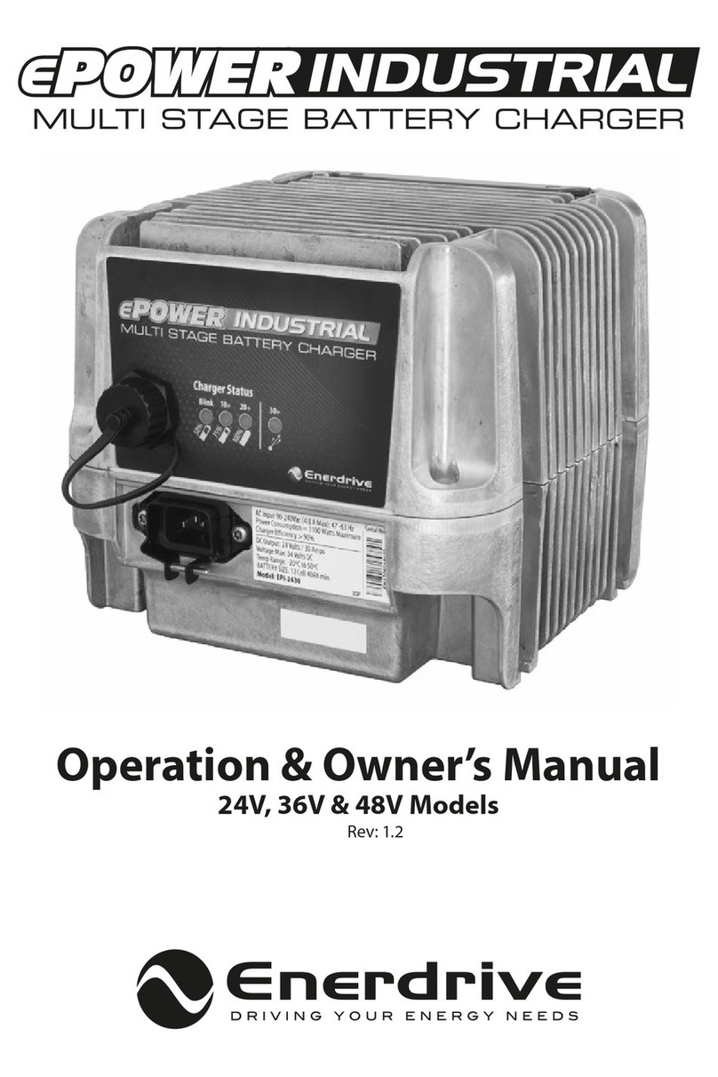
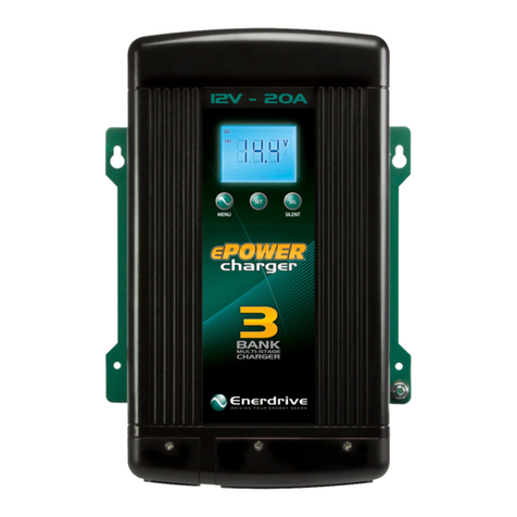
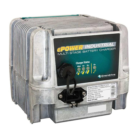
Enerdrive ePRO EPBC-1290 User manual

Owner’s Manual
ePRO Battery Charger 12V / 90Amp
ePRO Battery Charger 24V / 50Amp
ePRO Battery Charger 24V / 80Amp
Enerdrive ePRO Battery Charger Owner’s Manual (Rev 1.0) January 2016

Enerdrive ePRO Battery Charger Owners Manual (Rev. 1.0)
Page 2
TABLE OF CONTENTS
1. INTRODUCTION
5
2. INSTALLATION 9
2.1 Unpacking 9
2.2 Mounting 9
2.3 Accessing the connection compartment 10
2.4 Wiring details 11
2.4.1 Control board connections and settings 13
2.4.2 Bottom side connections 14
2.5 Parallel operation 15
3. CONFIGURING THE BATTERY CHARGER 16
3.1 Selecting the correct charge program 16
3.2 Charge programs explained 18
4. GENERAL OPERATION 20
4.1 ePRO Battery Charger display and control overview 20
4.2 Charging batteries 21
4.3 Equalizing a ooded battery 22
5. TROUBLESHOOTING GUIDELINE 24
6. TECHNICAL SPECIFICATIONS 27
7. WARRANTY 28

PLEASE KEEP THIS MANUAL FOR FUTURE REFERENCE
For safe and optimum performance, the Enerdrive ePRO Battery Charger must be used
properly. Carefully read and follow all instructions and guidelines in this manual and give
special attention to the CAUTION and WARNING statements.
Disclaimer
While every precaution has been taken to ensure the accuracy of the contents of this guide,
Enerdrive assumes no responsibility for errors or omissions. Note as well that specications
and product functionality may change without notice.
Important
Please be sure to read and save the entire manual before using your Enerdrive ePRO Battery
Charger. Misuse may result in damage to the unit and/or cause harm or serious injury. Read
manual in its entirety before using the unit and save manual for future reference.
Product Numbers - ePRO Battery Charger Series
EPBC-1290 ePRO Battery Charger 12V / 90Amp
EPBC-2450 ePRO Battery Charger 24V / 50Amp
EPBC-2480 ePRO Battery Charger 24V / 80Amp
ePRO Battery Charger Owners Manual Rev. 1.0. This Manual is applicable to all units with
serial number prex EPBC.
Service Contact Information
ENERDRIVE PTY LTD
Unit 11, 1029 Manly Road Tingalpa, Queensland, Australia 4173
Ph: 1300 851 535 / Fax: 07 3390 6911
Email: sales@enerdrive.com.au | Web: www.enerdrive.com.au
www.enerdrive.com.au
Page 3

NOTICE OF COPYRIGHT
Enerdrive ePRO Battery Charger owner’s manual © 2016 Enerdrive . All rights reserved. No
part of this document may be reproduced in any form or disclosed to third parties without
the express written permission of Enerdrive Pty Ltd, Unit 11, 1029 Manly Road Tingalpa,
Queensland, Australia 4173. Enerdrive reserves the right to revise this document and to
periodically make changes to the content hereof without obligation or organization of such
revisions or changes, unless required to do so by prior arrangement.
EXCLUSIONS FOR DOCUMENTATION AND PRODUCT USAGE
1.
Unless specically agreed to in writing, Enerdrive Pty Ltd : makes no warranty as to the
accuracy, suciency or suitability of any technical or other information provided in its
manuals or other documentation
2.
Assumes no responsibility or liability for losses, damages, costs or expenses, whether
special, direct, indirect, consequential or incidental, which might arise out of the use of such
information. The use of any such information will be entirely at the user’s risk
3. Makes no warranty, either expressed or implied, including but not limited to any implied
warranties of merchantability or tness for a particular purpose, regarding these Enerdrive
products and makes such Enerdrive products available solely on an “as is” basis.
4.
Shall in no event be liable to anyone for special, collateral, incidental, or consequential
damages in connection with or arising out of purchase or use of these Enerdrive products.
The sole and exclusive liability to Enerdrive, regardless of the form of action, shall not exceed
the purchase price of the Enerdrive products described here in.
Enerdrive ePRO Battery Charger Owners Manual (Rev. 1.0)
Page 4

1. INTRODUCTION
Thank you for purchasing the Enerdrive ePRO Battery Charger. With our state of the art, easy
to use design, this product will oer you reliable service for providing a multistage, multi-
bank battery charger to charge the dierent types of batteries you have installed in either
your home, boat, caravan or commercial vehicle. This manual will explain how to use this unit
safely and eectively. Please read and follow these instructions and precautions carefully.
IMPORTANT SAFETY INFORMATION
This section contains important safety information for the Enerdrive ePRO Battery Charger.
Each time, before using the Enerdrive ePRO Battery Charger, READ ALL instructions and
cautionary markings on or provided with the battery charger, and all appropriate sections of
this guide. The Enerdrive ePRO Battery Charger contains no user serviceable parts. Opening
up the charger will void product warranty. See Warranty section for how to handle product
issues.
WARNING
FIRE AND/OR CHEMICAL BURN HAZARD
Do not cover or obstruct any air vent openings and/or install in a zero-clearance
compartment.
WARNING
SHOCK HAZARD. KEEP AWAY FROM CHILDREN!
Avoid moisture ingress. Never expose the unit to snow, water, etc.
www.enerdrive.com.au
Page 5

WARNING
FAILURE TO FOLLOW THESE INSTRUCTIONS CAN
RESULT IN DEATH OR SERIOUS INJURY
When working with electrical equipment or lead acid batteries, have someone nearby
in case of an emergency.
Study and follow all the battery manufacturer’s specic precautions when installing,
using and servicing the battery connected to the charger.
Wear eye protection and gloves.
Avoid touching your eyes while using this unit.
Keep fresh water and soap on hand in the event battery acid comes in contact with eyes.
If this occurs, cleanse right away with soap and water for a minimum of 15 minutes and
seek medical attention.
Batteries produce explosive gases. DO NOT smoke or have an open spark or re near
the system.
Never attempt to re-charge a damaged, frozen or non-rechargeable battery.
Keep unit away from moist or damp areas.
Avoid dropping any metal tool or object on the battery. Doing so could create a spark or
short circuit which goes through the battery or another electrical tool that may create
an explosion.
Battery charger must be plugged in to an earthed and Australian Standards compliant
mains supply. If the units power cable is damaged, replace the cable immediately.
Enerdrive ePRO Battery Charger Owners Manual (Rev. 1.0)
Page 6

WARNING: EXPLOSION HAZARD!
DO NOT use the Enerdrive
ePRO Battery Charger
in the vicinity of ammable fumes
or gases (such as gas bottles or large engines).
AVOID covering the ventilation openings. Always operate unit in an open and well
ventilated area.
Prolonged contact to high heat or freezing temperatures will decrease the working life
of the unit.
LIMITATIONS OF USE
Do not use in connection with life support systems or other medical equipment or devices.
Charger is not to be used by persons with reduced physical or mental capabilities or lack
of knowledge and experience. Not to be operated or used by children.
www.enerdrive.com.au
Page 7

2. INSTALLATION
2.1 Unpacking
The charger package should contain the following items :
Battery charger
Wall bracket
Battery temperature sensor (3m)
Owner’s manual
Safety yer
Charger warning stickers
2 x M8 crimp terminals
7 x mounting screws
2.2 Mounting
Please see the image below for the mounting method.
Enerdrive ePRO Battery Charger Owners Manual (Rev. 1.0)
Page 8

The image below shows the mutual distances of the drilling holes.
206mm
103mm
178mm
28mm
5mm
37mm
237mm
CAUTION
Keep a clear space of at least 10 cm around this product for cooling purposes! Always
mount this product in an upright position. Floormounting is allowed as well, provided
that all 7 screws are used to secure the enclosure.
www.enerdrive.com.au
Page 9

WARNING
To reduce the risk of explosion, never use this product in locations where there is danger
of gas- or dust explosions or where ignition protected equipment is mandatory. Never
install the charger directly on top of the battery or vice-versa.
2.3 Accessing the connection compartment
To access the connection compartment, remove the two screws indicated on the left and
slide the red connection compartment cover downwards.
WARNING
Never operate this product without having the cover re-installed!
Enerdrive ePRO Battery Charger Owners Manual (Rev. 1.0)
Page 10

2.4 Wiring details
Please see the image below for the wiring details.
1
Please consult the following table to determine the correct battery cable
and fuse size for each model. Using a smaller cable size or a longer cable will
cause additional losses and may result in improperly charged batteries. Fire
and burning hazards are present if the battery cables are insuciently sized
for the expected current. Battery cable lengths longer than 6 meters, are not
recommended.
battery voltage:
EPBC-1290 : 12V
EPBC-2450 : 24V
EPBC-2480 : 24V
battery capacity:
EPBC-1290 : 180 - 900Ah
EPBC-2450 : 100 - 500Ah
EPBC-2480 : 160 - 800Ah
battery voltage:
EPBC-1290 : 12V
EPBC-2450 : 24V
EPBC-2480 : 24V
battery capacity:
EPBC-1290 : 180 - 900Ah
EPBC-2450 : 100 - 500Ah
EPBC-2480 : 160 - 800Ah
battery voltage:
EPBC-1290 : 12V
EPBC-2450 : 24V
EPBC-2480 : 24V
battery capacity:
EPBC-1290 : 180 - 900Ah
EPBC-2450 : 100 - 500Ah
EPBC-2480 : 160 - 800Ah
www.enerdrive.com.au
Page 11

Model Cable size
(*length ≤ 3 m)
Cable size
(*length = 3 to 6m)
Battery fuse
(quick type)
EPBC-1290 35mm2 (AWG2) 50mm2 (AWG0) 100-120Amp
EPBC-2450 25mm2 (AWG3) 35mm2 (AWG2) 60-80Amp
EPBC-2480 35mm2 (AWG2) 50mm2 (AWG0) 100-120Amp
* Note: Cable size length is a total of both the Positive and Negative cable run.
2
The AC input must be protected by an earth leakage circuit breaker with over-current
protection (RCBO), that can withstand the maximum nominal current consumption
from the charger without tripping. All AC wiring must be sized accordingly. Please
consult the following table to determine the correct AC wiring and RCBO sizes:
Model AC wiring size / RCBO size
(220-240VAC)
AC wiring size / RCBO size
(100-120VAC)
EPBC-1290 1.5mm2 (AWG15) / 8A (30mA) 2.5mm2 (AWG13) / 16A (30mA)
EPBC-2450 1.5mm2 (AWG15) / 10A (30mA) 4mm2 (AWG11) / 20A (30mA)
EPBC-2480 2.5mm2 (AWG13) / 16A (30mA) -
Please make sure that the information in this table is in accordance to all locally applicable
electrical regulations.
3Up to 3 battery banks can be connected to the charger. Each output can supply the
full rated charging current. The total charging current of all 3 outputs combined, will
never exceed the maximum rated charging current. All 3 outputs are isolated from
each other by highly ecient active rectiers.
WARNING
The schematic (left) shows a typical standalone installation. No guarantees are given on
the compliance of any local electrical regulations. Please make sure that the complete
installation is made in accordance to all locally applicable electrical regulations.
WARNING
This Class I product must be earthed! Always connect the PE wire or chassis ground
screw at the bottom of the enclosure to your central ground (vehicle chassis, grounding
system of your boat etc.)
Enerdrive ePRO Battery Charger Owners Manual (Rev. 1.0)
Page 12

CAUTION
Always connect the negative (-) cable directly on the negative terminal of the battery, or
on the “loadside” of a current shunt. Always keep positive and negative cables close to
each other to minimize electromagnetic elds. Double check for correct polarity, before
connecting the battery cables to the battery! Wrong polarity may damage the charger.
CAUTION
Please feed all connection compartment wiring through the rubber grommets and
plastic gland.
2.4.1 Control board connections and settings
The following image shows the control board connections and switch options.
1
Master/slave switch position. This switch must be set to ‘MASTER’ when a single
charger is installed. The ‘SLAVE’ setting is only relevant for parallel charger systems.
www.enerdrive.com.au
Page 13

2
5 pole screw terminal block. The rst three positions are connected to the ‘normally
open’, ‘normally closed’ and ‘common’ contacts of the internal alarm relay. This relay will
be activated when the charger shuts down into an error mode. When the error condition
has been cleared, this relay will de-activate again. Please make sure not to exceed the
maximum relay contact rating of 60V and 5A to avoid damaging the relay or PCB.
On the 4th and 5th position of the screw terminal, an external switch can be connected
to remotely turn the charger on and o. This switch can be located up to 50 meters
away from the charger. It is advised to use a wire size of 1mm2 (AWG17) for the remote
switch connection. For the remote switch, any single pole switch can be used. Only a
low power signal must be switched on this line.
3
Remote bypass switch position. When a remote switch is connected to the 5 pole
screw terminal block, the remote bypass switch must be set to OFF. When no remote
switch is used, the remote bypass switch must be set to ON.
2.4.2 Bottom side connections
Please see the next image for the bottom side connections.
Enerdrive ePRO Battery Charger Owners Manual (Rev. 1.0)
Page 14

2.5 Parallel operation
Up to 6 battery chargers of the same model can be connected in parallel, in order to reach
very high charge current levels. This manual will not show any connection or operation
details for paralleled charger systems. Such details are explained in the documentation
that is included with the optional “ePRO Battery Charger XL Parallel Kit (Part.# EPBC-PK)”.
www.enerdrive.com.au
Page 15

3. CONFIGURING THE BATTERY CHARGER
3.1 Selecting the correct charge program
The image in chapter 2.4 showed the location of the rotary selector, which is used to select
the desired charge program. The charge program selection depends on the type of battery
that needs to be charged. Each battery type has its own typical bulk and oat charge voltages.
When your battery type or optimal charging voltages are still not available in the standard
list, you can select rotary position ‘0’ and setup the battery charger using the Dashboard for
Windows software. This software is included in the optional ePRO Link to USB Communication
Kit (Part.# 5092120), which also contains an isolated interface box required to connect the
ePRO Battery Charger to a PC. Using Dashboard, all available parameters can be edited, and
it is also possible to edit or create your own battery charge programs.
CAUTION
Invalid battery type settings can cause serious damage to your batteries and/or connected
battery loads. Always consult your battery’s documentation for the correct charge voltage
settings.
In the following table, all settings are explained.
Selector
position
Battery type Voltage (12V/24V) and maximum timer settings
Position 0
Custom
(empty from
factory)
The voltage settings for this position are empty.
Connect the charger to a PC running Dashboard
and create a custom charge program to save on this
position. If not, the charger will return a battery error
when the selector is set to ‘0’.
Position 1
Flooded
(factory
default
setting)
Absorption voltage = 14.40V or 28.80V
Float voltage = 13.50V or 27.00V
Equalize voltage = 15.80V or 31.60V
Max. bulk time = 8hrs
Max. absorption time = 4hrs
Enerdrive ePRO Battery Charger Owners Manual (Rev. 1.0)
Page 16

Position 2
GEL Absorption voltage = 14.20V or 28.40V
Float voltage = 13.50V or 27.00V
Equalize voltage = equalize not available
Max. bulk time = 8hrs
Max. absorption time = 4hrs
Position 3
AGM (also
for Optima
SpiralCell)
Absorption voltage = 14.70V or 29.40V
Float voltage = 13.65V or 27.30V
Equalize voltage = 15.50V or 31.00V
Max. bulk time = 8hrs
Max. absorption time = 4hrs
Position 4
Lead Calcium Absorption voltage = 14.80V or 29.60V
Float voltage = 13.50V or 27.00V
Equalize voltage = 15.80V or 31.60V
Max. bulk time = 16hrs
Max. absorption time = 8hrs
Position 5
LiFePO4 Absorption voltage = 14.40V or 28.80V
Float voltage = 13.80V or 27.60V
Equalize voltage = equalize not available
Max. bulk time = 12hrs
Max. absorption time = 12hrs
Position 6
Empty Reserved for future use. If selected anyway, the charger
will return a battery error.
Position 7
Empty Reserved for future use. If selected anyway, the charger
will return a battery error.
Position 8
Empty Reserved for future use. If selected anyway, the charger
will return a battery error.
www.enerdrive.com.au
Page 17

Position 9
Empty Reserved for future use. If selected anyway, the charger
will return a battery error.
This manual will only describe the rotary selector settings. Conguration by Dashboard will be
explained in the Dashboard manual that comes with the ePRO Link to USB Communication Kit.
3.2 Charge programs explained
Most standard selectable charge programs, perform a four stage IUoUoP charging process
comprising of a “Bulk” , an “Absorption”, a “Float” and a “Pulse” stage. The image below
visualizes the four stage charging process :
Enerdrive ePRO Battery Charger Owners Manual (Rev. 1.0)
Page 18

In the Bulk stage, the charger delivers full output current and typically returns approximately
80% of charge back into the battery once the absorption voltage is reached. During this
stage, indicators 3d and 3c (see frontpanel image in chapter 4.1) will be lit depending on
the Bulk charge progress.
When the absorption voltage has been reached, the Absorption stage will be entered and
indicator 3b will be lit. This stage will return the nal 20% of charge to the battery. The
output voltage is kept at a constant level and the charge current decreases as a function of
the battery’s state of charge. When the charge current has dropped below a certain value
or when the maximum absorption timer has been expired, the Float stage will be entered.
Indicator 3a will be lit and an acoustical message will sound, indicating that the battery is
full. In this stage the battery voltage will be held constant at a safe level for the battery. It
will maintain the battery in optimal condition for as long as the battery remains connected
to the activated charger. Connected battery loads will be directly powered by the charger
up to the charger’s maximum output current level. When even more current is drawn, the
battery must supply this which results in a declining battery voltage. At a certain battery
voltage level, the charger jumps back to the Bulk stage and will nalize a complete four
stage charging process again, once the battery load consumption has dropped below the
charger’s maximum output current level.
The fourth stage called “Pulse”, will perform a short refresh charge of approximately 1 hour
each 7 days while the charger operates in the Float stage. This will keep the battery in optimal
condition while prolonging it’s lifetime. The battery can remain connected to the activated
charger continuously, without risk of overcharging.
When the battery temperature sensor is installed, the charger automatically compensates
the charge voltages against battery temperature. This means that the charge voltages are
slightly increased at lower temperatures and decreased at higher temperatures (-30mV/°C
at 12V chargers and -60mV/°C at 24V chargers). This way, overcharging is prevented which
prolongs your battery’s lifetime. A connected battery temperature sensor also enables
the battery temperature protection, which stops the charging process when the battery’s
temperature is below -20°C or above +50°C.
www.enerdrive.com.au
Page 19

4. GENERAL OPERATION
4.1 ePRO Battery Charger display and control overview
See the next image for an overview of all LED indicators on the ePRO Battery Charger
frontpanel, as well as the location of the main switch.
The frontpanel can be divided into four sections :
1Output current bar. Indicates the percentage of total delivered charging current.
2Mode indicator. Indicates the operating mode of the battery charger
Indicator mode Description
Continuous green Power on, normal mode
Flashing red (1 ash per sec.) Battery error
A battery error can appear for several reasons. These are
: battery voltage is too low (too deeply discharged) or too
high and battery temperature is too low or too high (only
available when battery temperature sensor is connected).
The charger will not restart automatically in battery error
mode, except when this error was generated due to a too
low battery voltage or a too low battery temperature.
Enerdrive ePRO Battery Charger Owners Manual (Rev. 1.0)
Page 20
This manual suits for next models
2
Table of contents
Other Enerdrive Batteries Charger manuals

Enerdrive
Enerdrive ePOWER DC2DC User manual

Enerdrive
Enerdrive DOMETIC EN31220 User manual

Enerdrive
Enerdrive ePOWER DC2DC User manual

Enerdrive
Enerdrive ePOWER Series User manual

Enerdrive
Enerdrive ePOWER Charger EN31220 User manual

Enerdrive
Enerdrive ePower Industrial EPI-2430 User manual

Enerdrive
Enerdrive ePower Industrial EPI-2430 User manual