EnergAir metacentre DX Box User manual

MANY0702A.GB – Metacentre DX Box Technical Manual
TM
DX Box
bar

Metacentre DX Box
Page 1
Index
1.0 Safety Precautions
1.1 Installation
1.2 Operational
1.3 Maintenance and Repair
2.0 Introduction
2.1 Management System Connectivity
2.2 Basic Function
2.3 Operation
3.0 Installation
3.1 Guidelines
3.2 Location
3.3 Power Supply
3.4 RS485 Connection
3.5 Compressor Interface PCB
3.6 System Pressure Sensor
3.7 Delivery Pressure Sensor (Option)
3.8 Auxiliary Fault Inputs (Option)
3.9 Remote Output (Option)
4.0 Commissioning
4.1 Commissioning Procedure
4.2 System Management Unit
4.3 Menu Navigation
4.4 Menu Items and Settings
4.5 Diagnostics
5.0 Operation
5.1 User Interface
5.2 Display
5.3 Status Symbols
5.4 Indications
5.5 Compressor Identification
5.6 Operation
5.7 Power Failure Auto-Restart
5.8 Failure Modes
5.9 Compressor Fault
5.10 DX Box Fault
5.11 Pressure Sensor Fault
6.0 Parts List
7.0 Technical Data
8.0 Wiring Connection Diagram
Technical Manual
Page 2
1. Safety Precautions
ALWAYS EMPLOY SAFE WORKING
PRACTISE AND PROCEDURES
WARNING:
Risk of Danger
WARNING:
Risk of Electric Shock
WARNING:
Risk of High Pressure
WARNING:
Consult Manual
When installing, commissioning, operating or
carrying out service or maintenance on a product,
personnel must use safe working practise and
observe all relevant local health and safety
requirements and regulations. Attention of users in
the UK is drawn to the Health and Safety at Work
Act, 1974, and to the Regulations and
Recommendations of the Institution of Electrical
Engineers (IEE).
Lethal voltages are used within the product. Use
extreme caution when carrying out electrical checks.
Isolate the power supply before starting any
maintenance work.
It is not possible to anticipate every circumstance
that might represent a potential hazard. If the user
employs an operating procedure, an item of
equipment or a method of working which is not
specifically recommended the user must ensure the
product will not be damaged or made unsafe and
that there is no risk to persons or property. Failure to
observe safety precautions or implement safe
working practises may be considered dangerous
practice or misuse of the product.
1.2 Installation
Installation work must only be carried out by a
competent person under qualified supervision.
A fused isolation switch must be fitted between the
main power supply and the product.
The product should be mounted in such a location
as to allow operational and maintenance access
without obstruction or hazard and to allow clear
visibility of indicators at all times.
If raised platforms are required to provide access to
the product they must not interfere with normal
operation or obstruct access. Platforms and stairs
should be of grid or plate construction with safety
rails on all open sides.
1.3 Operation
The product must only be operated by competent
personnel under qualified supervision.
Never remove or tamper with safety devices, guards
or insulation materials fitted to the unit.
The product must only be operated at the supply
voltage and frequency for which it is designed.
When mains power is switched on, lethal voltages
are present in the electrical circuits and extreme
caution must be exercised whenever it is necessary
to carry out any work on the unit.
Do not open access panels or touch electrical
components while voltage is applied unless it is
necessary for measurements, tests or adjustments.
This work must only be carried out by a qualified
electrician or technician equipped with the correct
tools and appropriate protection against electrical
hazards.
All air compressors and/or other machine equipment
connected too, and controlled by, the product should
have a warning sign attached stating ‘THIS UNIT
MAY START WITHOUT WARNING' next to the
display panel.
If an air compressor and/or other machine
equipment connected too, and controlled by, the
product is to be started remotely, attach warning
signs to the machine stating ‘THIS UNIT CAN BE
STARTED REMOTELY’ in a prominent location,
one on the outside of the machine, the other inside
the machine control compartment.
1.3 Service Maintenance and Repair
Service, maintenance, repairs or modifications must
only be carried out by competent personnel under
qualified supervision.
If replacement parts are required use only genuine
parts from the original equipment manufacturer, or
an alternative approved source.
Carry out the following operations before opening or
removing any access panels or carrying out any
work on the product :-
• Isolate from the main electrical power supply.
Lock the isolator in the 'OFF' position and
remove the fuses.
• Attach a label to the isolator switch and to the
product stating ‘WORK IN PROGRESS - DO
NOT APPLY VOLTAGE'. Do not switch on
electrical power or attempt to start the unit if
such a warning label is attached.
Ensure that all instructions concerning operation
and maintenance are strictly followed and that the
complete product, with all accessories and safety
devices, is kept in good working order.
The accuracy of sensor devices must be checked
on a regular basis. They must be renewed when
acceptable tolerances are exceeded. Always ensure
any pressure within a compressed air system is
safely vented to atmosphere before attempting to
remove or install a sensor device.
The product must only be cleaned with a damp
cloth, using mild detergents if necessary. Avoid the
use of any substances containing corrosive acids or
alkalis.
Do not paint the control facial or obscure any
indications, controls, instructions or warnings.
Metacentre DX Box
Page 3
2. INTRODUCTION
The DX Box is designed to connect two
load/unload air compressors to a system
management unit, using a 2-wire RS485 data
cable up to 500m (1650ft) in length.
The DX Box is designed specifically to ‘group’
two compressors together as a single
coherent unit. The system management unit
will detect and manipulate the two
compressors as a single multiple step or
variable output compressor unit.
The DX Box is able to manipulate two identical
capacity compressors to form a single ‘group’
that will act in an identical manner as a 3-step
compressor. The DX Box is also able to
manipulate two differential capacity
compressors providing demand matched
control and sequence to form a single ‘group’
that will act in an identical manner as a
variable stepping output, compressor.
This functionality provides the ability to:
a) Group two adjacent air compressors
together as a single coherent unit.
b) Combine two similar capacity
compressors together to form a three-
step variable output group acting as a
single coherent variable output unit.
c) Take advantage of a small or minimal
capacity compressor, grouped
together with a medium or higher
capacity compressor, to form a high
capacity, variable output, group acting
as a single variable output ‘top-up’
compressor.
d) Exceed the maximum compressor
control capability of a system
management unit by combining
compressors together as one.
Two single pressure switch control type air
compressors can be connected to the DX Box
using a 6-wire cable and a compressor
interface PCB (i-PCB). The ‘i-PCB’
connections are identical to an system
management unit.
The DX Box also provides optional ‘local
pressure sensor’ connections. The
compressor delivery pressures, local system
pressure and air treatment differential
pressures can be displayed. The monitored
local pressure is available on the system
network and can be utilised by an system
management unit for advanced pressure
related functions.
Any number of DX Boxes can be connected to
an system management unit as long as the
total number of single compressors and/or
groups does not exceed the total number of
compressors for the system management unit
model.
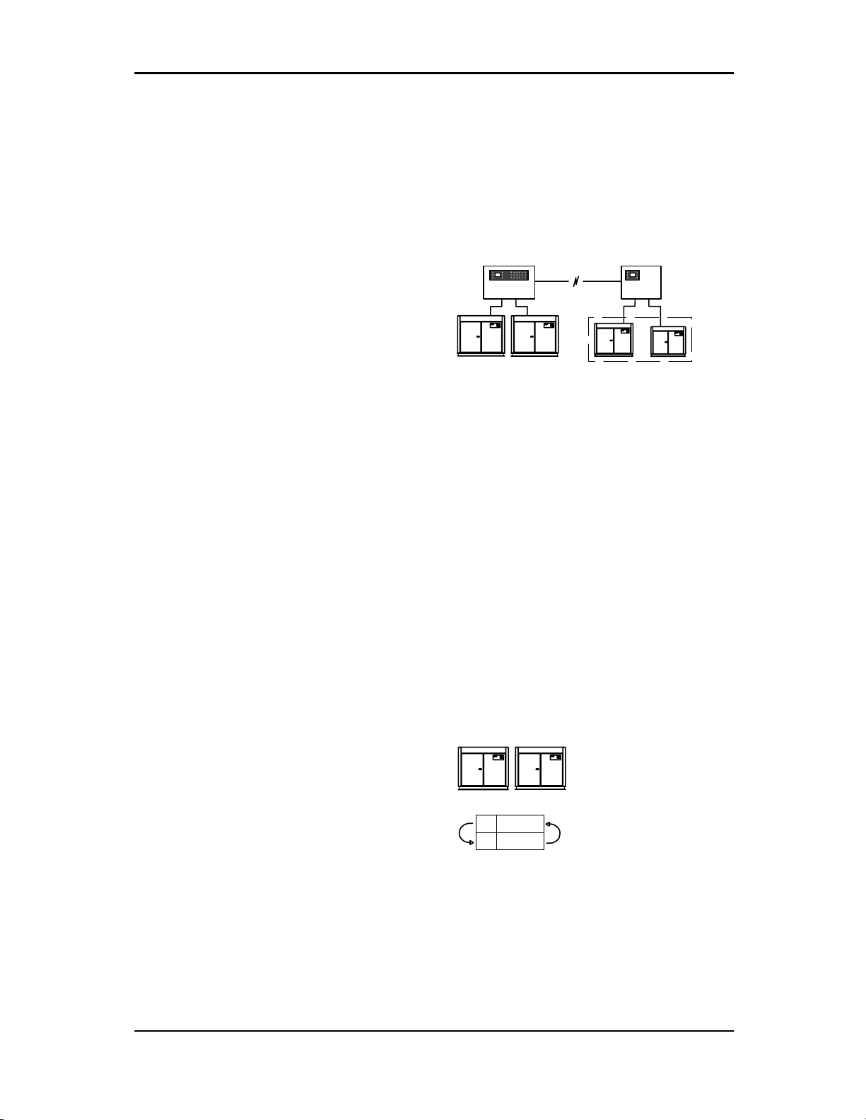
2.1 Management System Connectivity
12 #1
DX Box
3#2
The DX Box connects to an ystem
management unit using an industrial two wire
RS485 data network (Multi485).
2.2 Basic Function
The DX Box is a ‘Duel unit eXtension’ to a
system management unit providing the ability
to group two individual air compressors
together in to one duel ‘group’ acting as a
single coherent unit.
The DX Box provides additional ‘i-PCB’
connectivity.
The DX Box can also be used to provide ‘i-
PCB’ connectivity at a remote location beyond
the maximum distance specification of direct
system management unit connection.
2.3 Operation
2.3.1 Timer Rotation Mode (Tr)
#1 #2
50% 50% = 100%
1AB
2BA
AB
Timer Rotation should be used when the two
compressors have the same (50:50), or very
similar, output capacity. The DX Box will
assign one compressor as ‘Duty’ and the other
as ‘Standby’. The duty compressor will always
be loaded first and the standby used as and
when required to meet demand. The duty and
standby assignment will be changed at every
‘Interval Time’ (adjustable).

Technical Manual
Page 4
2.3.2 Automatic Mode (Ar)
#1 #2
65% 35% = 100%
0% - -
35% - B
65% A -
100% A B
AB
Automatic mode can be used when the
compressor capacities are different. The DX
Box will utilise each compressor as required to
match output to demand. This mode enables
the compressor ‘group’ to behave in the same
manner as a single (multiple step) variable
output unit.
The set ‘Interval Time’ is ignored in this mode,
the DX Box will continuously evaluated
utilisation to match demand.
For example:
If demand can be satisfied by the smaller of
the two compressors (demand < 36%) the DX
Box will utilise the lower capacity compressor
(B). If demand increases above the output
capacity of the smaller compressor, but within
the capacity of the larger capacity compressor,
the DX Box will utilise the larger capacity
compressor (A). If demand exceeds to
capacity of the larger capacity compressor the
DX Box will load the larger compressor
continuously and utilise the smaller capacity
compressor to regulate as required.
2.3.3 Management System Integration
When integrated with a system management
unit the DX Box compressor ‘group’ will
respond in ‘Top-Up’ mode or ‘Base-Load’
mode as dictated by the management unit.
The assigned mode of response will change
from time-to-time dependant on the set
sequencing mode of the management unit.
In Top-Up’ mode the DX Box will allow
variable capacity control (as described above)
dependant on demand.
In ‘Base-Load’ mode the DX Box will fully load
both compressors to provide full base-load
capacity output.
The DX Box ‘group’ unit should be set as a
variable output unit on the management
system. The management system will fully
utilise the variable output capacity capability of
the DX Box ‘group’ and report the percentage
of utilisation of the ‘group’ in the same manner
as a single variable output compressor.
2.3.4 Percentage Capacity
The capacity of each compressor is
expressed, and set, as a percentage of the
combined output capacity of both
compressors.
For example:
If the larger compressor #1 (A) has an output
capacity of 13.0m3/min, and the smaller #2 (B)
compressor an output capacity of 7.0m3/min,
the total combined output of the DX Box
‘group’ equates to 20.0m3/min.
Total Capacity (20.0m3/min.) = 100%
Compressor #1 (A) = 65%
Compressor #2 (B) = 35%
2.3.5 Compressor Failure Mode
If one compressor in the DX Box ‘group’
suffers a shutdown failure, or is manually
stopped, the DX Box will indicate an ‘Alarm’
condition. The remaining compressor will
continue to function and the DX Box will
continue to operate at reduced capacity.
If both compressors suffer a shutdown failure,
or are manually stopped, the DX Box will
indicate a shutdown ‘Trip’ condition.
Metacentre DX Box
Page 5
3. Installation
3.1 Guidelines
It is recommended that installation and
commissioning be carried out by an authorised
and trained product supplier.
3.2 Location
The DX Box is wall mounting using
conventional screw fixings. The DX Box can
be located remote from the compressor units
but within 100m (330ft) cable length from each
compressor and within 100m (330ft) cable
length from any pressure sensor option (if
applicable).
3.3 Power Supply
A fused switching isolator must be installed to
the main incoming power supply, external to
the DX Box. The isolator must be fitted with a
fuse of the correct rating to provide adequate
protection to the power supply cable used (in
accordance with local electrical and safety
regulations).
1
VOLTAGE SELECT
234
X04
1
VOLTAGE SELECT
234
X04
230Vac
115Vac
EELN
NLE
X01
1234
XPM-TAC24
Check the input voltage select link wires on
the DX Box power supply PCB, adjust if
necessary.
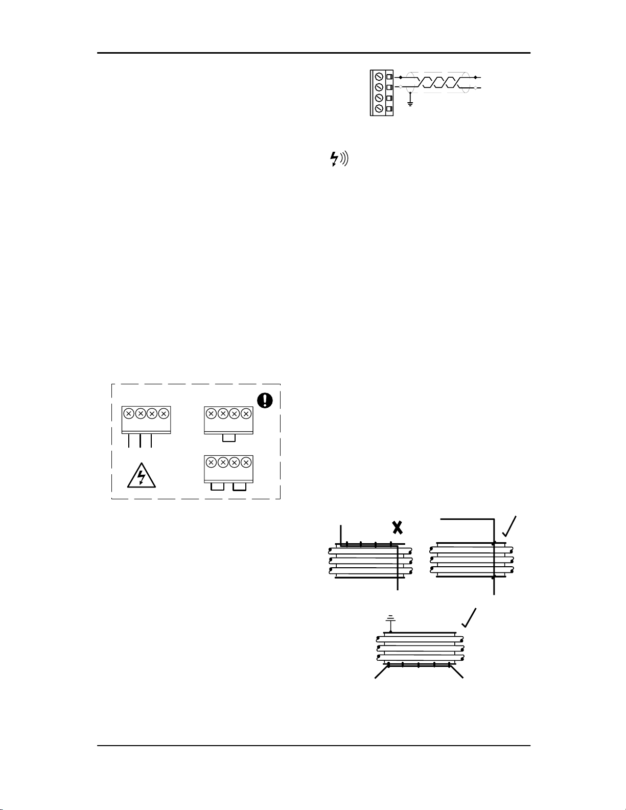
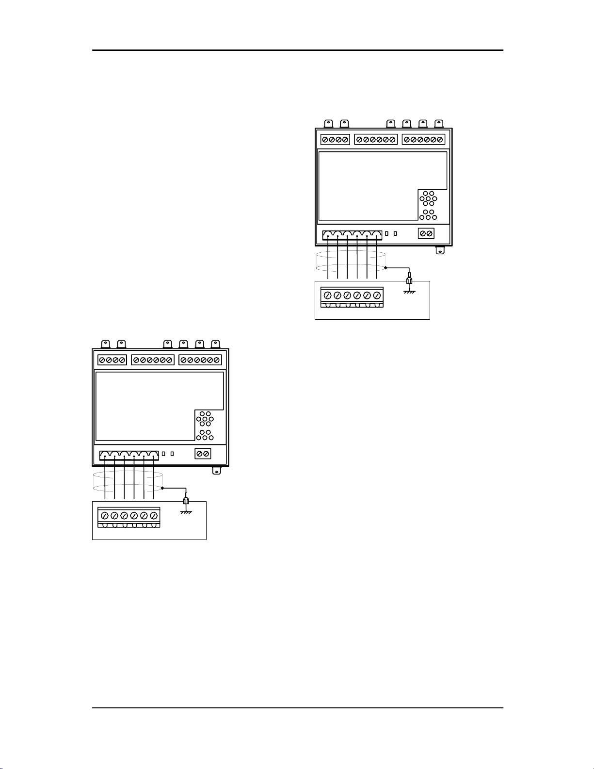
3.4 System RS485 Connection
The DX Box is intended to operate as part of a
managed system. Connection to the system
management unit is two-wire, twisted pair,
earth shielded, RS485 data link. Connect the
RS485 data cable wires to terminal X07.
26
28
25
27
X07 L2
L1
RS485
Note: Polarity is important.
RS485 data communications and other
low voltage signals can be subject to electrical
interference. This potential can result in
intermittent malfunction or anomaly that is
difficult to diagnose. To avoid this possibility
always use earth shielded cables, securely
bonded to a known good earth at one end. In
addition, give careful consideration to cable
routing during installation.
1) Never route an RS485 data
communications or low voltage signal cable
alongside a high voltage 3-phase power
supply cable. If it is necessary to cross the
path of a power supply cable(s), always cross
at a right angle.
2) If it is necessary to follow the route of power
supply cables for a short distance (for
example: from a compressor unit to a wall
along a suspended cable tray) attach the
RS485 or signal cable on the outside of an
earthed cable tray such that the cable tray
forms an earthed electrical interference shield.
3) Where possible, never route an RS485 or
signal cable near to equipment or devices that
may be a source of electrical interference (for
example: 3-phase power supply transformer,
high voltage switchgear unit, frequency
inverter drive module, radio communications
antenna).
Technical Manual
Page 6
3.5 Compressor Interface PCB
An ‘i-PCB’ is designed for connection to an DX
Box controller using a six-wire (earth shielded)
cable no greater than 100m (330ft) in length.
Each compressor in the system must be
assigned an identification number from 1 up to
the number of compressors in the system. The
identification number should be clearly
indicated on each compressor for operational
reference.
The DX Box can be connected to any two
compressors in an system management unit
network. The compressor identification
numbers will need to be re-designated to
reflect that the two compressors are now in a
single coherent group and will be regarded by
the management system as a single unit.
The ‘i-PCB’ of the first compressor (#1 or ‘a’)
to be connected to the DX Box must be
connected to the six terminals dedicated for
compressor reference #1.
i-PCB
LED 1 LED 2
C01 C02 C04
C03
246
135
X01
DX Box
246
135
#1
The ‘i-PCB’ of the second compressor (#2 or
‘b’) to be connected to the DX Box must be
connected to the six terminals dedicated for
compressor reference #2.
i-PCB
LED 1 LED 2
C01 C02 C04
C03
810 127 9 11
X02
DX Box
2 4 61 3 5
#2
Interface PCB (i-PCB):
The ‘i-PCB’ is a DIN rail mountable unit
designed to be installed within the compressor
control or switchgear area and connected to
the DX Box using a six-wire cable.
Each air compressor must be equipped with a
load/unload regulation system and, if not
regulated with a single electro-mechanical
pressure switch, have a facility for a remote
load/unload control with the ability to accept a
volt-free switching contact input for remote
load/unload.
Note: consult the air compressor manual or
your air compressor supplier/specialist for
details before installing the DX Box unit.
The ‘i-PCB’ uses a 12V to 250V ac/dc input
voltage detection system and universal relay
contact control outputs (250Vac/dc @ 5A
maximum). Integrated directly into the circuits
of an air compressor, the ‘i-PCB’ avoids the
need for additional relays or remote inputs.
The ‘i-PCB’ also acts as an electrical barrier
between the compressor and the DX Box
providing protection and voltage isolation.

Metacentre DX Box
Page 7
3.5.1 Input Functions
The ‘i-PCB’ is fitted with a six-pin terminal C04
for compressor monitoring. The ‘i-PCB’ uses
two inputs (Ready and Run) to determine
compressor status. An Alarm input can be
used if compressor alarm indication is
available and required. The Alarm input is
optional and is not necessary for system
control.
Ready Input:
The ‘Ready’ connection is intended to indicate
that the compressor is in a ‘started’ state, has
no operational inhibiting fault condition and is
ready to respond to DX Box regulation without
manual intervention.
0V
+V
READY LAMP
RUN READY
ALARM C04
The READY input will accept 12V to 250V ac
(50/60Hz) or dc.
Caution: Do not connect a voltage greater
than 250Vac/dc to this input.
This input must be connected to the terminals
of a ‘ready’ or ‘operational’ lamp, or other
circuit of the compressor control system, that
will be energised when the compressor is in
started (standby or running) condition.
The voltage to this input must de-energise
when the compressor is stopped and
unavailable to produce air upon a load signal,
or the Emergency Stop button is pressed, or
when the compressor experiences a fault that
prevents the compressor from running.
When the compressor ready lamp, or other
control circuit, is energised the ‘i-PCB’ will
detect the voltage and signal the DX Box that
the compressor is ready and available to load
and produce air when a load request signal is
given.
Note: The ‘i-PCB’ input common terminal must
always be connected to the neutral, common
or 0V line of the applied input
Ready Input, Alternative Connection Method:
In instances where a convenient voltage signal
for a compressor ready condition is not
available the ‘Ready’ input can be connected
directly to a constant compressor control
system power supply voltage (12V to 250Vac
or dc). This will signal the DX Box that the
compressor is ready and available at all times
when power is applied to the compressor. The
DX has a built-in function to determine when a
compressor is not responding, or is in a
shutdown condition, regardless of a constant
ready signal. If the DX Box requests a
compressor to run/load, but fails to detect a
RUN signal within 60 seconds, the DX Box will
regard the compressor as ‘not ready’ and
indicate the compressor as not available. If a
RUN signal is detected at any time, the DX
Box will automatically reset the compressor
‘not ready’ condition and re-establish control.
F1
+Vac
0Vac
READY
Safety: Never connect the READY input
positive connection directly to the output of a
control system transformer, always connect
after a fuse or circuit breaker.
If a normally closed contact of an Emergency
Stop button is included in the compressor
power supply circuit, connect after the
Emergency Stop button contacts. This will
instantly indicate a compressor ‘not ready’
condition if the Emergency Stop button is
activated.
Technical Manual
Page 8
Run Input:
0V
RUN READY
ALARM
+V
MAIN (LINE) CONTACTOR
C04
The RUN input will accept 12V to 250V ac
(50/60Hz) only (DC cannot be used).
Caution: Do not connect a voltage greater
than 250V to this input.
12V to 250Vac must be applied to the ‘Run’
terminals when the compressor motor is
running.
This input can be connected to the control
terminals A1 and A2 (coil) of the main starter
contactor of the compressor. When the
compressor control system energises the main
contactor, the ‘i-PCB’ will detect the voltage
across the contactor coil terminals and signal
the DX Box that the compressor is running.
Alternatively, if the main contactor coil voltage
is greater than 250Vac, a contactor auxiliary
switch can be used to apply a suitable voltage
to the ‘Run’ input terminals.
0V
+V
MAIN (LINE) CONTACTOR
0V
+V
AUXILIARY SWITCH
RUN READY
ALARM C04
In instances where a motor starter contactor is
not available or accessible, any part of a
compressor control circuit that is energised
when the compressor is running can be
monitored. For example: fan contactor or
voltage signal to a remote starter.
Note: The ‘i-PCB’ input common terminal
must always be connected to the neutral,
common or 0V line of the applied input
voltage.
Alarm Input:
The ‘i-PCB’ is equipped with an alarm (or
warning) input that can be used to detect
alarm or warning conditions.
Note: A fault, that stops the compressor,
and/or prevents the compressor from running,
is determined from the ‘Run’ and ‘Ready’
inputs; Alarm detection is optional and is not a
requirement.
Alarm Run Ready
Alarm Lamp 0V
+V
C04
The Alarm input will accept 12V to 250V ac
(50/60Hz) or dc.
Caution: Do not connect a voltage greater
than 250Vac/dc to this input.
This input can be connected to the terminals of
an alarm lamp or other accessible part of the
control circuit that is energised when the
compressor is in an alarm condition.
If an alarm condition is experienced the
compressor alarm lamp, or alarm circuit, will
energise. The ‘i-PCB’ will detect the voltage
and signal the DX Box that an alarm has
occurred. If the compressor has no accessible
alarm circuit, or this function is not required,
the ‘i-PCB’ alarm terminals can be ignored.
Note: The ‘i-PCB’ input common terminal must
always be connected to the neutral, common
or 0V line of the applied input voltage.

Metacentre DX Box
Page 9
3.5.2 Output Functions
The DX Box will control the ‘i-PCB’
load/unload relay outputs in accordance with
the set system load and unload pressure set
points. The ‘i-PCB’ load/unload relay contacts
can be used for compressor controllers that
have ‘pressure switch’ load/unload regulation.
‘i-PCB’ Internal Output Circuits
OUT
NO
IN
NO
OUT
NC IN
NC
IN
C
Load
C
Seq
SEQ
Relay
1&2
LOAD
Relay
3
OUT
C
+20VDI2DI1
GND
LOAD
UNL
SEQ
CONT
Contacts :-
250Vac/dc @ 5A
maximum
24Vac
C
C03
1
2
3
The C01 and C02 terminal functions of the ‘i-
PCB’ are intended to control load and unload
regulation of the compressor.
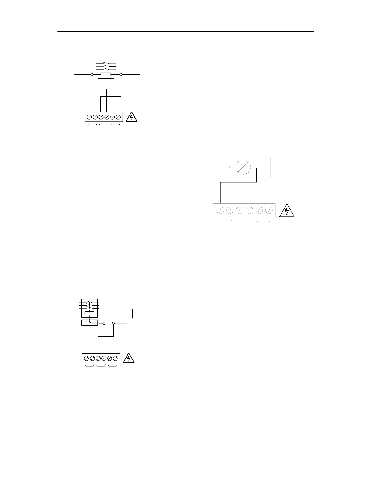
Pressure Switch Regulation:
For air compressors fitted with an electro-
mechanical pressure switch a six-pin terminal
C02 has been provided to enable connection
to a pressure switch that has a two wire or
three-wire connection.
When connected the pressure switch remains
in circuit. If the DX Box is stopped or
experiences a failure or loss of power,
pressure control will automatically revert back
to the pressure switch and the compressor will
continue to operate in ‘Local’ mode.
Note: The local pressure settings of all
compressors in the system should be set in a
cascaded manner such that the system will
operate normally in the event of system
management unit inoperability.
Note: The NC (normally closed) and NO
(normally open) terminal references of the ‘i-
PCB’ are related to internal connection
functions and should not be referenced to the
connections of a compressor pressure switch
(which will generally be in reverse order).
Lethal voltages may be present on the
terminals of the air compressor pressure
switch. Isolate the air compressor power
supply before starting any work.
Two Wire Pressure Switch Connections:
+V
0V
LOAD
SOLENOID
C02
NO
OUT
C
NC
NO
C
NC
IN
Three Wire Pressure Switch Connections:
+V 0V
LOAD
SOLENOID
RUN-ON
TIMER
C02
NO
OUT
C
NC
NO
C
NC
IN

Technical Manual
Page 10
Remote Load/Unload Regulation:
For air compressors controllers fitted with
‘Remote/Local Pressure Regulation’ digital
inputs, a 4-pin connector C01 has been
provided.
This terminal provides volt free contact closure
for load control and also provides volt free
contact closure for remote pressure control
enable.
A remote load enable input provides the facility
to change the compressor load regulation from
internal control to a remote switching source.
Note: Compressors that use electronic
pressure detection but are not equipped with a
remote pressure control enable feature will not
automatically revert to local control if the DX
Box is stopped or experiences a fault or loss of
power.
Load and Sequence Connection:
Inputs Common
Remote Load Local/Remote
or
Remote Load Enable
COMPRESSOR CONTROLLER
INPUTS
C01
C
LOAD
C
SEQ
Note: Compressor controller inputs common
voltage may be 0V or +V.
The local/remote pressure regulation input
and/or remote load input logic of some
electronic pressure sensor type controllers are
reversed, in this instance the ‘pressure switch’
outputs (terminal C02) can be used to
establish alternative logic control connections.
For Example:
If the compressor controller ‘Local/Remote
Pressure Control’ input is a normally open
type; Remote when closed, but the ‘Remote
Load’ input is a normally closed type; load
when open, the ‘i-PCB’ pressure switch
terminal contacts can be used to achieve the
correct switching logic.
C02
NO
OUT C
NC
NO
C
NC
IN
common
common
Local/Remote
Remote Load
Examine the ‘i-PCB’ internal output circuit
diagram to establish any desired switching
logic that may differ from normal practise.
Do not attempt to utilise the Load/Seq
‘Electronic Pressure Control’ (terminal C01)
and the ‘Pressure Switch Control’ (terminal
C02) output connections at the same time.
These two output functions are internally
connected and a short circuit condition and/or
malfunction may result.
Note:
The ‘i-PCB’ connection examples shown in
this manual are intended to provide a guide for
the majority of compressor control systems in
use. Some compressors have variations in
operation and/or function; consult your
compressor supplier/specialist for advice.

Metacentre DX Box
Page 11
3.5.3 Service Maintenance Switch:
(Optional)
The ‘i-PCB’ is equipped with a volt-free input
(terminal C05) that can be used to remove the
compressor from DX Box control without
generating a fault condition during
maintenance or servicing periods. The DX Box
‘group’ will continue to operate at reduced
maximum output capacity. If both compressors
are set for service/maintenance the DX Box
will indicate to the system management unit
that the DX Box ‘group’ is in maintenance
mode; the system management unit will
remove the DX Box ‘group’ from the sequence
strategy and substitute with an alternative
available compressor if necessary.
1
2
C05
When the ‘Service Maintenance Switch’ input
terminal pins are connected together, using a
volt-free switching contact, the DX Box will
detect that the compressor is in maintenance
mode and unavailable for utilisation. When the
‘Service Maintenance Switch’ inputs are open
circuit again the compressor will automatically
be accepted back in to DX Box control.
The use of a ‘key switch’ is recommended for
this purpose in order to prevent the switch
contacts being inadvertently left in the closed
circuit condition after service maintenance is
complete.
DO NOT connect any external voltage
source to the pins of terminal C05.
Note: If both compressors are switched to
maintenance mode at the same time the
responce of the system management unit will
be dependant on model; only models equipped
with ‘Service Maintenance Switch’ functionality
will recognise the maintenance mode.
Activating the ‘Service Maintenance’ function
with an system management unit that is not
equipped for the function will result in a DX
Box ‘group’ fault indication.

Technical Manual
Page 12
3.6 System Pressure Sensor
Required for DX Box operation.
A pressure sensor input is available for
monitoring local ‘system’ or ‘dry-side’ pressure
downstream of local air treatment or other
potential restrictions to air flow. This input is
intended for a 4-20mA type pressure sensor.
The pressure sensor should be installed in
such a manner as to be able to sample
atmospheric pressure during routine
calibration procedures. It is recommended that
a valve be used that will allow the sensor to be
removed without de-pressurisation of the air
system.
Connect the pressure sensor to the ‘System’
(REF) pressure sensor input terminals of the
DX Box.
The pressure sensor must be connected to the
DX box using a 2-wire, earth shielded, cable
that is no longer than 100m (330ft) in length.
X05
+
-
+
-
26
25
Polarity is important.
Some types of pressure sensor are not
suitable for direct exposure to water (e.g. rain,
condensate, steam or excess moisture) or
direct sunlight. In this instance the sensor
must be protected from the environment if it is
to be mounted in a location exposed to
climatic or adverse conditions.
3.7 Delivery Pressure Sensor (optional)
The ‘Compressor Delivery’ pressure option
can provide local over-pressure protection and
air treatment differential monitoring.
#1
#2
DP#2
Ps
P1
P2 DP#1
Compressor Delivery Pressure:
A pressure sensor input is available for each
compressor connected to the DX Box. This
input is intended for a 4-20mA type pressure
sensor that is installed to monitor the ‘delivery’
pressure of the applicable compressor.
It is recommended the pressure sensor should
be installed up-stream of (before) any isolation
valve and in such a manner as to be able to
sample atmospheric pressure during routine
calibration procedures.
Connect the pressure sensor to the correct DX
Box terminals for the applicable compressor.
The pressure sensor must be connected to the
DX box using a 2-wire, earth shielded, cable
that is no longer than 100m (330ft) in length.
X05
22
24
21
23
#1
#2
#1
+
-
+
-
#2
+
-
+
-
Polarity is important.
Metacentre DX Box
Page 13
3.8 Auxiliary Fault Inputs (Option)
The DX Box is equipped with two auxiliary
‘Fault’ inputs, one dedicated to each
compressor. The input(s) can be used to
detect a compressor ‘Alarm’ or ‘Shutdown
Trip’ condition. The input(s) can also be used
to detect a ‘Fault’ condition of auxiliary
equipment associated with the compressor.
The function of each ‘Fault’ input can be
selected in the DX Box menu:
1: Alarm
The system management unit will display the
fault as a compressor ‘Alarm’ condition; the
compressor will continue to run and be utilised
as required.
2: Trip
The system management unit will display the
fault as a compressor ‘Shutdown Trip’
condition; the compressor will be removed
from sequence and will not be utilised.
Fault Comp #1
Fault Comp #2
X04
16
18
15
17
#1
#2
As default the auxiliary ‘Fault’ input(s) are
normally open, Fault on closed circuit
condition. If required this can be reversed in
the DX Box menu to be normally closed, Fault
on open circuit.
Note: The maximum cable length for an
Auxiliary ‘Fault’ input is 100m (330ft).
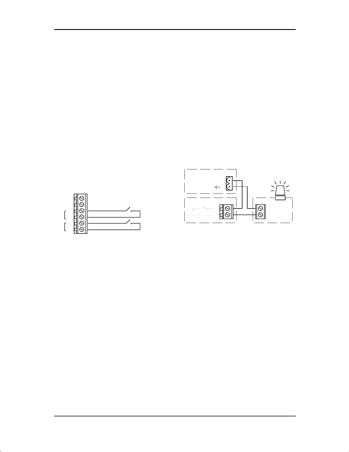
3.9 Remote Output (Option)
Remote Output R4
The DX Box is equipped with a remote relay
contact output; terminal X03. The function of
the output can be defined in the DX Box menu.
The contacts of the remote relay output can be
used to switch an external devise or signal a
remote condition or fault condition.
The remote relay contacts are rated for
24Vac/dc @ 5A maximum.
Alarm Beacon:
An Alarm Beacon kit is available that can be
connected to the DX Box remote output to
provide a highly visible fault indication from a
distance.
2
1
X03
+
-24Vac
Beacon
R2
24Vac
XPM-TAC24 X03
14
13
The unused 24Vac @ 1A power supply output
of the XPM-TAC24 power supply PCB
(terminal X03) can be used to provide the
beacon 24Vac supply.
Note: Pin ‘1’ of X03 (0vac) is bonded to earth
on the XPM-TAC24 module PCB.

Technical Manual
Page 14
4. COMMISSIONING
4.1 Commissioning Procedure
Carry out the following procedures before
attempting to apply power and start.
It is recommended that an authorised and
trained product supplier carry out
commissioning.
4.1.1 Power Supply PCB Voltage Selector:
Before applying power to the DX Box ensure
that the power supply connections are correct
and secure and that the operating voltage
selector is set correctly for the power supply
voltage in use; 115Vac or 230Vac (+-10%),
50/60Hz; see ‘Installation’.
1
VOLTAGE SELECT
234
X04
1
VOLTAGE SELECT
234
X04
230Vac
115Vac
EE
N
L
LNE
X01
1234
XPM-TAC24
General Checks:
Check and ensure all pressure sensor, ‘i-PCB’
and other connections are correctly installed
and secure.
Close the front panel of the DX Box and apply
power.
4.2 System Management Unit
Ensure the connection type for the DX Box
‘group’ is defined as “I-485” (RS485 network
communication) in the system management
unit configuration.
Each DX Box ‘group’ connected to an system
management unit must be assigned a unique
compressor identification number (1 to 12).
This number will be the ‘network address’
number for the DX Box ‘group’. This number,
and the DX Box identification (‘A’ or ‘B’) should
be clearly marked on the compressor for
identification purposes; for example ‘3A’.
When connecting a DX Box to a system
always use the system management unit
unique compressor identification number as
the DX Box ‘network address’ number.
12 #1
DX Box
3#2
Indicate each compressor connected to the
DX Box using the DX Box compressor
identification number and the compressors
local reference number #1 or #2.
Example:
Compressor #1 = network address 3(#1)
Compressor #2 = network address 3(#2)
The local DX Box reference numbers (#1 and
#2) have no meaning for system management
unit identification and referencing; it is not
important for compressors to be connected to
the DX Box in numerical order or sequentially.
The management system will indicate both
compressors as a single unit with one
identification number.

Metacentre DX Box
Page 15
4.3 Menu Navigation
Display Item Structure:
All value, parameter or option selection
displays are grouped into menu lists. Items are
assigned to a list according to type and
classification. Items that can be used to select
options or modify functions are assigned to
‘menu mode’ lists. Items that a User may
require to view during routine operation,
detected pressure for example, are assigned
to the normal operational mode list. Lists are
identified by page number; the normal User
display list is page ‘P00’. All parameters and
options are assigned to menu mode pages
‘P01’ or higher. All Page ‘P00’ items are view
only and cannot be adjusted.
Normal Operational Mode (Page P00):
At controller initialisation, all display elements
and LED indicators are switched on for three
seconds, the display will then show the
software version code for a further 3 seconds
before initialisation is complete and the normal
operating display (Page P0) is shown. In page
P00 ‘normal operational display mode’ the
main display will continuously show the
detected delivery pressure and the Item
display will show the first item of the ‘User’
menu. User menu ‘Items’ can be selected
using the Up or Down buttons at any time.
Pressing the Enter button will lock any
selected Item display and inhibit return to the
default display. When an Item display is locked
the lock key symbol will slow flash. To unlock
an Item display press Up or Down to view an
alternative Item display or press Reset or
Escape. No Item values, options or
parameters can be adjusted in page ‘P00’. If a
fault condition occurs the fault code becomes
the first list item and the display will
automatically jump to display the fault code.
More than one active fault code item can exist
at any one time.
Access Code:
Access to page list displays higher than page
‘P00’ is restricted by access code. To access
menu mode pages press UP and DOWN
together, an access code entry display is
shown and the first code character will flash.
Use PLUS or MINUS to adjust the value of the
first code character then press ENTER. The
next code character will flash; use UP or
DOWN to adjust then press ENTER. Repeat
for all four code characters.
If the code number is less than 1000 then the
first code character will be 0(zero). To return
to a previous code character press ESCAPE.
When all four code characters have been set
to an authorized code number press ENTER.
An invalid code will return the display to
normal operational mode; page ‘P00’.
Access Code Timeouts:
When in menu mode, if no key activity is
detected for a period of time the display will
automatically reset to the normal operational
display; Page ‘P00’.
Menu Mode Navigation:
In menu mode the main value display will flash
and show the Page number. To select a page
press UP or DOWN. For each page the
display will show the first Item of the page list.
To view a page list press ENTER, the Page
number will stop flashing and the Item display
will flash. Press UP or DOWN to view the
selected page list items. To select an Item
value for modification press ENTER, the Item
display will stop flashing and the Value display
will flash. The value or option can now be
modified by pressing UP(Plus) or
DOWN(Minus). To enter a modified value or
option in memory press ENTER; alternatively
the modification can be abandoned, and the
original setting maintained, by pressing
ESCAPE.
Page 3
Page 2
Page 1
Item 1 Value
Item 2 Value
Item 3 Value
Item 4 Value
Item 5 Value
Page 0
Item 1 Value
Item 2 Value
Item 3 Value
Item 4 Value
Item 5 Value
Item 6 Value Page 5
Page 4

Technical Manual
Page 16
Press ESCAPE at any time in menu mode to
step backwards one stage in the navigation
process. Pressing ESCAPE when the page
number is flashing will exit menu mode and
return the display to normal operational mode;
page ‘P00’.
Press and hold RESET for two seconds at
any time to immediately exit menu mode and
return to the normal operational mode display.
Any value or option adjustment that has not
been confirmed and entered into memory will
be abandoned and the original setting
maintained.
A flashing Key symbol displayed with
any Item indicates the Item is locked and
cannot be modified. This will occur if the Item
is view only (non adjustable) or in instances
where the item cannot be adjusted while the
DX Box is in ‘Remote Mode’.
Page 3
Page 2
Page 1
Item 1 Value
Item 2 Value
Item 3 Value
Item 4 Value
Item 5 Value
Page 0
Item 1 Value
Item 2 Value
Item 3 Value
Item 4 Value
Item 5 Value
Item 6 Value Page 5
Page 4
Metacentre DX Box
Page 17
4.4 Menu Items and Settings
Menu 1 – Comp #1 Settings
1Pc Comp #1 Percent Capacity
2D3 ‘i-PCB’ Alarm Input 0V/+V (Di3)
3 D6 Auxiliary Input (Di6)
Menu 2 – Comp #2 Settings
1Pc Comp #2 Percent Capacity
2D5 ‘i-PCB’ Alarm Input 0V/+V (Di5)
3 D7 Auxiliary Input (Di7)
Menu 3 – Configuration
1Ad
DX Box network Address
2Mo Mode
3 Rt Rotation Interval time
4 St Start Delay time
5P> Pressure display units
6 R4 Auxiliary Output Function (R4)
Menu 4 – Regulation Control
1C> Control percent (view only)
2Pf P Factor
3 If I Factor
Menu 5 – System Pressure Sensor
2 Po Offset Calibration
3 Pr Range Calibration
Menu 6 – Comp #1 Pressure Sensor
1PE Enable
2PL Pressure Limit
3 Po Offset Calibration
4 Pr Range Calibration
Menu 7 – Comp #2 Pressure Sensor
1PE Enable
2PL Pressure Limit
3 Po Offset Calibration
4 Pr Range Calibration
Menu 7 - Diagnostics
See ‘Diagnostics’
Access Code = 0021
4.4.1 Menu 1 – Compressor #1
Menu items for compressor #1
Pc: Percent Capacity
Set to the percentage output compared to the
total output of the DX Box ‘group’.
For example: If compressor #1 = 13.0 m3/min
and compressor #2 = 7.0 m3/min then:
Compressor #1 = 65%
D3: ‘i-PCB’ Alarm Input NO/NC
‘i-PCB’ Alarm input configuration for
compressor #1.
As default the ‘i-PCB’ Alarm input (optional)
will generate an Alarm condition when voltage
(12V to 250V) is applied to the Alarm input
terminals (‘no’).
This configuration can be changed so that a
constant voltage can be applied to the Alarm
input terminals and an Alarm generated when
the voltage is removed. (‘nc’).
‘no’ (normally open) – default
Alarm when voltage applied.
‘nc’ (normally closed)
Alarm when voltage removed.
Set to default ‘no’ if not used.
D6: Auxiliary Input
Selects the function and operation of the
‘Auxiliary Input’:
Ano Alarm: (normally open) – default
Alarm when closed
Anc Alarm: (normally closed)
Alarm when open
Tno Trip: (normally open)
Trip when closed
Tnc Trip: (normally closed)
Trip when open
Set to default ‘Ano’ if not used.

Technical Manual
Page 18
4.4.2 Menu 2 – Compressor #2
Menu items for compressor #2
Pc: Percent Capacity
Set to the percentage output compared to the
total output of the DX Box ‘group’.
For example: If compressor #1 = 13.0 m3/min
and compressor #2 = 7.0 m3/min then:
Compressor #2 = 35%
D5: ‘i-PCB’ Alarm Input NO/NC
‘i-PCB’ Alarm input configuration for
compressor #2.
As default the ‘i-PCB’ Alarm input (optional)
will generate an Alarm condition when voltage
(12V to 250V) is applied to the Alarm input
terminals (‘no’).
This configuration can be changed so that a
constant voltage can be applied to the Alarm
input terminals and an Alarm generated when
the voltage is removed. (‘nc’).
‘no’ (normally open) – default
Alarm when voltage applied.
‘nc’ (normally closed)
Alarm when voltage removed.
Set to default ‘no’ if not used.
D7: Auxiliary Input
Selects the function and operation of the
‘Auxiliary Input’:
Ano Alarm: (normally open) – default
Alarm when closed
Anc Alarm: (normally closed)
Alarm when open
Tno Trip: (normally open)
Trip when closed
Tnc Trip: (normally closed)
Trip when open
Set to default ‘Ano’ if not used.
4.4.3 Menu 3 – Configuration
DX Box configuration items.
Ad: Network Address
DX Box network address; must be set to the
compressor identification number used by the
system management unit controller for the DX
Box ‘group’ (1 to 12). Each DX Box and/or
compressor in a system must have a unique
identification number.
Note: The DX Box network address number
must be unique and must not be set the same
as any other compressor or DX Box ‘group’ in
a system.
Mo: Mode (see: Operation)
0: Timer Rotation
1: Automatic (default)
Rt: Rotation Interval Time
1 to 24 Hours (24hrs default)
The time interval between ‘Top-Up’ and ‘Base-
Load’ rotation of the compressors connected
to the DX Box.
Note: Only applicable in ‘Timer Rotation’
mode.
St: Start Delay Time
If it is necessary for the DX Box to ‘start’ the
main motors of both compressors together,
compressor #2 will not be started until the start
delay time has expired after compressor #1
has been started. Set to the ‘star/delta’ time of
the largest compressor in the group.
P>: Pressure Units
Selects the display pressure units:
0: bar (default)
1: psi
2: kPa

Metacentre DX Box
Page 19
R4: Auxiliary Output Function
Selects the function of the auxiliary relay
contact output R4.
Fno: Compressor Fault N/O
Energised if a compressor Alarm or Trip
fault is detected.
Fnc: Compressor Fault N/C
De-energised if a compressor Alarm or
Trip fault is detected.
C1r: Compressor #1 Running
Energised when compressor #1 is
detected as running.
C2r: Compressor #2 Running
Energised when compressor #2 is
detected as running.
Crr: Compressor Running
Energised if compressor #1 and/or
compressor #2 is detected as running.
On: Metacentre ON
Energised when Metacentre
management system is regulating to
achieve or maintain pressure (Off when
in standby or stopped).
AC: Metacentre Active
Energised when Metacentre
management system is actively
maintaining control of compressors
inclusive of Standby (Off when stopped;
unless management system set to force
compressors offload when stopped)
rPC: Remote Pressure Control
Energised when in ‘Remote Mode’ –
System management unit control.
CS: Compressor(s) in Maintenance Mode
Energised when one, or both,
compressors have been switched to
Service/Maintenance mode.
4.4.4 Menu 4 – Regulation Control
C>: Control percent (view only)
The DX Box uses a P&I pressure control
algorithm to determine compressor utilization.
The control algorithm produces a percentage
value that is compared to the percentage
settings of each compressor. The ‘control
percentage’ will increase and decrease in
response to changes in local system pressure
‘SP’. When the DX Box is operating in
conjunction with a system management unit
the algorithm ‘target’ response is automatically
manipulated to match the system
requirements.
Pf: P Factor (default 40)
If: I Factor (default 10)
Example % Control Functions:
100.0
90.0
80.0
70.0
60.0
50.0
40.0
30.0
20.0
10.0
0.0
%
50:50%
50%
Control
100%Display:
A A+B
50%
‘x’
‘x’
‘y’
‘y’
75.0%
25.0%
100.0
90.0
80.0
70.0
60.0
50.0
40.0
30.0
20.0
10.0
0.0
%
65:35%
65%
Control
35%
35% 100%Display:
A A+B
B
65%
82.5%
‘z’
‘z’
‘x’
‘x’
‘y’
‘y’
50.0%
17.5%
Do not adjust the ‘P’ and/or ‘I’ factor
setting(s) unless you are familiar with the P&I
control response and the function of these
settings within the P&I control algorithm.
Other manuals for metacentre DX Box
1
Table of contents
Other EnergAir Control System manuals

Popular Control System manuals by other brands


RichAuto
RichAuto AutoNow F141 user manual

J&D MAnufacturing
J&D MAnufacturing JD-MV1 Installation & user guide

Intermatic
Intermatic T51211BC supplementary guide

Yamaha
Yamaha RGX620Z Guide

Alltech
Alltech Manual Barrier quick start guide

Union Switch & Signal
Union Switch & Signal Microlok II Functional description


