HWH 110 Series User manual

OPERATOR’S MANUAL
ML10039/MP05.1001/LHD-K
26FEB04
Four Lever Control
Hydraulic Leveling
FEATURING:
HWH CORPORATION
(On I-80, Exit 267 South)
2096 Moscow Road | Moscow, Iowa 52760
Ph: 800/321-3494 (or) 563/724-3396 | Fax: 563/724-3408
www.hwh.com
110 SERIES LEVELING SYSTEM
HWH LEVER-CONTROLLED
Kick-Down Jacks
Suspension Air Dump
AP10039
W
CORPORATION
HH
R
HWH HYDRAULIC LEVELING
LEVELING
WARNING
EXTEND
DUMP
OFF
FUSE
5 AMP
USING. BLOCK FRAME AND TIRES BEFORE REMOVING
TIRES OR CRAWLING UNDER VEHICLE.
UNDERSTAND OPERATOR’S MANUAL BEFORE
CAUTION!
STORE
H
CORPORATION
H
W
R
LR LF RF RR
LR LF RR
RF
INTEGRATED CONTROLS
LEVEL
R

CAUTION !
READ THE ENTIRE OPERATOR’S MANUAL BEFORE OPERATING.
MOVE FORWARD OR BACKWARD WITHOUT WARNING CAUSING INJURY OR DEATH.
EXTENSION.
CAUSING INJURY OR DEATH.
CHIPS, OIL LEAKS, ETC. FOLLOW ALL OTHER APPLICABLE SHOP SAFETY PRACTICES.
NOTE: KEEP THE CONTROL VALVE LEVERS IN THE STORE POSITION WHEN JACKS ARE NOT IN USE.
OPERATOR’S MANUAL
BLOCK FRAME AND TIRES SECURELY BEFORE CRAWLING UNDER VEHICLE. DO NOT USE LEVELING JACKS OR AIR
SUSPENSION TO SUPPORT VEHICLE WHILE UNDER VEHICLE OR CHANGING TIRES. VEHICLE MAY DROP AND/OR
THE JACKS MAY ABRUPTLY SWING UP WHEN THE FOOT CLEARS THE GROUND OR WHEN JACK REACHES FULL
NEVER PLACE HANDS OR OTHER PARTS OF THE BODY NEAR HYDRAULIC LEAKS. OIL MAY PENETRATE SKIN
WEAR SAFETY GLASSES WHEN INSPECTING OR SERVICING THE SYSTEM TO PROTECT EYES FROM DIRT, METAL
IMPORTANT: IF VEHICLE IS EQUIPPED WITH A ROOM EXTENSION, READ ROOM EXTENSION SECTION BEFORE
OPERATING LEVELING SYSTEM.
IF THIS VEHICLE IS EQUIPPED WITH KICK-DOWN STYLE JACKS, DO NOT OVER EXTEND THE REAR JACKS. IF
THE WEIGHT OF THE VEHICLE IS REMOVED FROM ONE OR BOTH REAR WHEELS, THE VEHICLE MAY ROLL FOR-
WARD OR BACKWARD OFF THE JACKS.
MP15
30MAY01
KEEP ALL PEOPLE CLEAR OF VEHICLE WHILE LEVELING SYSTEM AND ROOM EXTENSION ARE BEING OPERATED.
problem, please do the following:
customer satisfaction. Therefore, if you discover a defect or
HWH CORPORATION strives to maintain the highest level of
THIS IS NOT TO BE INTERPRETED AS A STATEMENT OF WARRANTY
HOW TO OBTAIN WARRANTY SERVICE
(563) 724-3396 OR (800) 321-3494. Give your name and
address, coach manufacturer and model year, date the
HWH CORPORATION 2096 Moscow Rd. Moscow IA. 52760
notify the Customer Service Department:
If your dealer cannot or will not solve the problem,
Service Department, at HWH CORPORATION.
the problem, he should immediately contact the Customer
the problem quickly. If the dealer has difficulty solving
management people are in the best position to resolve
vehicle or had the leveling system installed. Dealership
Notify the dealership where you purchased the
SECOND:
FIRST:
authorized by HWH CORPORATION, or at the
must be performed by an independent service facility
determined by HWH CORPORATION. All warranty repairs
authorization of an independent service facility, to be
defective part, either by appointment at the factory or by the
CORPORATION will authorize repair or replacement of the
determine whether or not your claim is valid. If it is, HWH
HWH CORPORATION personnel will contact you to
during business hours (8:00 a.m. till 5:00 p.m. c.s.t.).
description of the problem, and where you can be reached
coach was purchased, or the date of system installation,
HWH CORPORATION factory, unless prior written approval
has been obtained from proper HWH CORPORATION
personnel.

CONTROL IDENTIFICATION
MP25.1010
18MAR97
HWH HYDRAULIC LEVELING
LEVELING
WARNING
EXTEND
DUMP
OFF
FUSE
5 AMP
USING. BLOCK FRAME AND TIRES BEFORE REMOVING
TIRES OR CRAWLING UNDER VEHICLE.
UNDERSTAND OPERATOR’S MANUAL BEFORE
CAUTION!
STORE
H
CORPORATION
H
W
R
LR LF RF RR
LR LF RR
RF
ROCKER SWITCH
"DUMP/LEVEL/OFF"
CONTROL CIRCUIT FUSE
(5 Amp)
ON/ MASTER
WARNING LIGHT
"LEVELING" LIGHTS
(4 - Yellow)
JACK CONTROL LEVER
(4)
LEVER CONTROLLED SYSTEM WITH INTEGRATED LIGHTS
"WARNING" LIGHTS
CONTROL FUNCTIONS
CONTROLS INDICATOR LIGHTS
(4 - Red)
CONTROL CIRCUIT FUSE:
JACK CONTROL LEVER:
ON/MASTER WARNING LIGHT:
"WARNING" LIGHTS:
"LEVELING" LIGHTS:
LEVEL
"DUMP/LEVEL/OFF" ROCKER SWITCH:
The fuse protects the panel.
jacks. Push a lever toward "EXTEND" to extend a jack or
"STORE" to retract a jack.
The light will be on if the ig-
nition is in the "ON" or "ACC" position and the "LEVEL/OFF"
rocker switch is in the "LEVEL" position or if one of the jacks
are extended 2 inches or more and the ignition switch is in
the "ON" or "ACC" position.
whenever the corresponding jack is extended 2 inches or more,
provided the ignition is in the "ON" or "ACC" position and the
system is on. Some coaches are equipped with a dash mount-
ed master "JACKS DOWN" light which will be on when one
or more jacks are extended 2 inches or more, provided the
ignition switch is in the "ON" position.
These levers control individual
A red "WARNING" light will be on
A lit yellow "LEVELING" light indi-
cates the corresponding corner is low. Extend the appropiate
jack(s) to put out the yellow light(s). One or two yellow lights
can be on at the same time. The vehicle is level when all
yellow lights are out.
This switch con-
trols power to the "LEVELING" and "WARNING" lights, and
the power unit. The "DUMP" position on the switch is a mo-
mentary position. Air will exhaust from the vehicle suspension
while the switch is held in the "DUMP" position. The switch
does not control the power to the master "JACKS DOWN"
warning light or the master WARNING light on the panel.

OPERATION PROCEDURES
LEVELING PROCEDURE
1. Place gear selector in the park position apply the park brake.
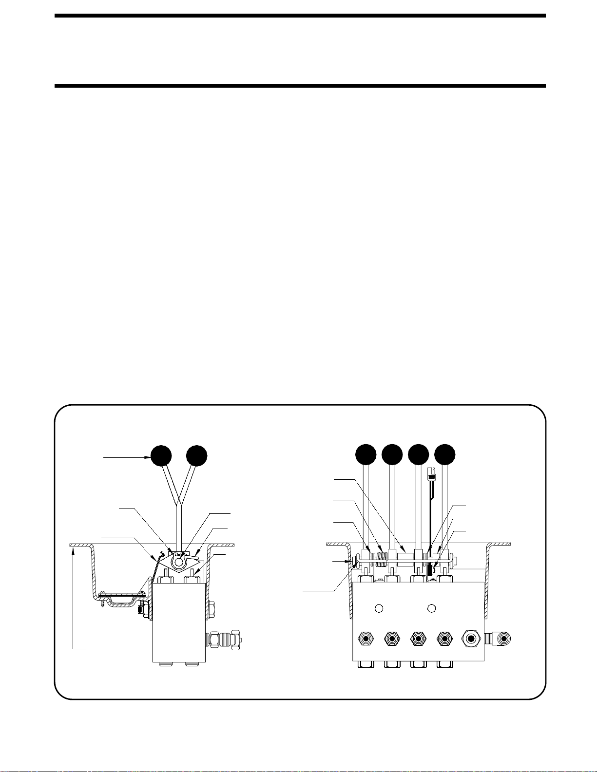
3. Push the rocker switch in jack control plate to "LEVEL".
4. Swing each jack to the vertical position by pushing each
control lever to "EXTEND". The respective red "WARNING" light
will light as soon as the jack swings vertical. Check that all
jacks have swung to the vertical position.
6. A lit yellow "LEVEL" light indicates that corner of the vehicle
is low. Extend jacks as needed to put out all the yellow lights.
7. After the vehicle is level, the jacks not used for leveling may be
extended until they touch the ground. This provides additional
stability against wind and activity in the vehicle.
8. Turn off the rocker switch on the leveling system panel.
9. Turn off the ignition switch.
or whenever the vehicle is used, to keep the system in good
operating condition.
Park with the front of the vehicle facing downhill if possible.
Care must be taken not to raise the rear of the vehicle too high
or the vehicle may roll forward or backward off the jacks. If
parking on soft ground or asphalt paving, wood blocks or
pads should be placed under the jacks.
SITE SELECTION
LEVELING TIPS: Two jacks maybe operated at the same time,
if desired. Operation of both side jacks at the same time often
provides a smoother lift while reducing stress on the vehicle
and jacks. If for example, a right front and a right rear yellow
"LEVEL" light is on, operate the right rear jack or the right
front and right rear jacks together. Right to left leveling is usu-
ally best accomplished using a rear jack or a front and rear
jack together. If a substantial amount of leveling is required,
it is often best to operate two jacks at the same time, leveling
If the ground is too uneven the jacks may not have enough
stroke to level the vehicle. The vehicle may have to be moved.
Remember that if the rear of the vehicle is lifted too high the
vehicle may roll forward or backward off the jacks.
side to side first.
ROOM EXTENSION PROCEDURES
read this section carefully.
If the vehicle is equipped with kick-down jacks, the wheels MUST
be blocked securely. Do NOT operate any room extension
until the leveling and stabilizing procedure is complete. Do
If the vehicle is equipped with a room extension
IMPORTANT:
NOT retract the leveling system until all room extensions are
retracted. NEVER operate the leveling system when any
Refer to the vehicle owner’s manual for proper operation of
room extensions are extended.
room extensions.
IMPORTANT: Do not use a room extension support when the
vehicle is supported by the leveling system.
Block tires securely.
2. Turn ignition switch to "ON" or "ACCESSORY". The vehicle
engine must be off. Running the engine during or after leveling
may inflate the air suspension, lifting the vehicle out of level.
5. Push and hold the rocker switch to the "DUMP" position
until the air is completely exhausted from the vehicle suspension
system.
IMPORTANT:
Overheating and excessive current draw will
result if control levers are partially operated toward "EXTEND"
for an extended period of time.
NOTE:
The leveling system should be cycled once a month
MP35.1028
09MAY97

OPERATION PROCEDURES
RETRACTING PROCEDURE
CAUTION:
2. Move the control levers to the "STORE" position. Retracting the
two rear jacks followed by the two front jacks will provide a smooth
retraction. As soon as a foot clears the ground, the jack will
swing horizontal and continue to retract.
THE CONTROL LEVERS SHOULD BE KEPT
IN THE "STORE" POSITION WHILE TRAVELING TO KEEP THE
4. Push the rocker switch on the jack control plate to "OFF". Turn
ignition off or proceed to travel.
CAUTION:
DO NOT RELY SOLELY UPON THE WARNING
LIGHTS. IT IS THE OPERATOR’S RESPONSIBILITY TO CHECK
THAT ALL JACKS ARE IN THE STORE/TRAVEL POSITION
BEFORE MOVING THE VEHICLE.
JACK POSITIONS
JACKS IN THE STORE/TRAVEL POSITION.
CAUTION:
MAKE SURE PEOPLE AND EQUIPMENT
ARE CLEAR OF THE VEHICLE.
3. Visually check that all jacks are in the STORE/TRAVEL
1. Start the vehicle engine and let air pressure build up in the
suspension.
EXTEND POSITION STORE/TRAVEL POSITION
position. With the ignition switch in the "ON" or "ACCESSORY"
position, and the system turned on, the red WARNING lights
and the master "JACKS DOWN" light will be out. Check that
the vehicle is at the proper ride height.
MP35.1030
09MAY97

MAINTENANCE
MP45
01JUN01
It is important that all of the jacks are fully retracted before
checking the hydraulic oil level. To check the oil supply, remove
the breather cap from the top of the hydraulic oil reservoir.
The oil level should be approximately one inch below the top of
the reservoir when adequately filled.
On the 9,000 lb. jacks and the 16,000 lb. jacks there are roller as-
semblies that need to rotate freely. (See above FIGURE) These
rollers should be cleaned with a penetrating fluid, such as WD-40,
and lubricated with a light oil as part of your regular maintenance
schedule.
In general, to insure the smooth operation of the leveling system,
it is a good idea to occasionally check the individual leveling
jacks to prevent problems. This is especially true under the unusual
conditions stated in the following:
If driving conditions are unusually muddy, the jacks may become
caked or clogged with mud. This condition may hamper the
proper operation of the leveling system. This problem may be
prevented or remedied by cleaning off each leveling jack if they
become excessively muddy.
In wet or icy weather leveling jacks may become encrusted with
ice. This may cause the leveling system to function improperly.
To eliminate this problem, periodically check the leveling jacks
and break loose any ice which may be causing improper operation.
Do not move the vehicle while the leveling jacks are still in
contact with the ground. However, if this should accidentally
happen, the leveling system was designed to protect itself
from damage in most cases. Place the system in the
STORE mode and then visually check to see if the leveling
jacks have returned to the STORE/TRAVEL POSITION.
All major components of the system can be replaced
with rebuilt parts or can be sent to HWH CORPORATION to
be rebuilt, when the system is out of warranty.
terminals and battery posts and connections should be kept
Weak batteries can cause erratic operation. Battery cable
The batteries should be in good condition and fully charged.
weathering.
should be clean, tight, free from corrosion and protected from
clean. All electrical connections, especially ground connections,
NOTE:
FLUID LEVELS
UNUSUAL CONDITIONS
ELECTRICAL SYSTEM
9,000 lb. JACK 16,000 lb. JACK
ROLLER
ASSEMBLY
JACK MAINTENANCE
emergency Dexron automatic transmission fluid can be used.
Dexron automatic transmission fluid contains red dye
and can cause staining should a leak occur. DO NOT USE
brake fluid or hydraulic jack fluid. Use of these can damage
HWH Specialty Hydraulic Oil is recommended. In an
NOTE:
seals.
FLUID:

There are two basic adjustments which are made at the time
of installation. However, when adjustment of a leveling unit
is needed, the following procedures are recommended.
Always make vertical adjustment first. If
the vertical adjustment is changed at anytime, be sure to check
the horizontal adjustment. Vertical position is changed by adjusting
Horizontal stop is adjusted by turning the set screws located
just inside the cable locknuts. The jack can be adjusted down
to provide clearance for objects which may interfere with the
operation of the jacks. The horizontal stop must be adjusted
to provide clearance between the hat bracket and mounting
bolts; and the actuator and hose fittings, when the jack is in
the STORE POSITION. The jack must be able to fully extend
in the horizontal position without interfering with suspension com-
Each jack should be checked to be sure
that it is vertical when it swings down. To do this, retract all
jacks, then extend each jack until it is close to, but not touching
the ground. If the jack stopped short of being vertical, it can
be adjusted by loosening the lower adjusting nut and tightening
the upper nut.
The horizontal stop can be adjusted up or down in the slot to
provide clearance for objects which may interfere with operation
If the jack stopped short of being vert-
ical loosen the set screw and turn the adjusting cap clockwise.
If the jack went beyond vertical, loosen the set screw and turn
the adjusting cap counterclockwise. After each adjustment,
the weight of the vehicle must be applied to the jack to make
the adjustment effective. DO NOT adjust cap more than one
turn without cycling the jack.
The horizontal stop on the heavy-duty jack is adjusted by adding
washers under the urethane stop.
MP45.0
13FEB03
MAINTENANCE
SYSTEM ADJUSTMENT
JACK ADJUSTMENT
ADJUSTING
UPPER
STANDARD &
LOW PROFILE
UNITS 9,000 lb. JACKS
ADJUSTING
LOWER
NUT NUT
STOP LEVELING
HEAVY DUTY
UNITS
16,000 lb. JACKS
ADJUSTING
SET SCREW
CAP
ADJUSTING
HORIZONTAL
ADJUSTMENT
VERTICAL
ADJUSTMENT
LOCK NUTS,
SET SCREW,
6,000 lb. JACKS
ponents, tanks, etc.
NOTE: The two front jacks should be adjusted to the same
horizontal position.
1. 6,000 lb. JACKS:
2. 9,000 lb. JACKS:
3. 16,000 lb. JACKS:
the lock nuts on the actuator cable. If the jack stopped short
of vertical, tighten the lock nuts. If the jack goes past vertical,
back the lock nuts off. Be sure to adjust each nut the same
number of turns.
of the jack. The stop must be adjusted so that the jack can be
fully extended in the horizontal position without interfering with
suspension components, tanks, etc.
LEVEL SENSING UNIT ADJUSTMENT
Level the vehicle by placing a circular bubble level in the
center of the freezer floor or location within the vehicle that
is to be level. With the vehicle level, adjust the sensing unit
until all yellow lights are off. This is done by drawing up the
corresponding screw if the sensing unit is mounted below
the surface as shown or backing out the corresponding
screw if the sensing unit is mounted above the surface.
Bump the sensing unit to see that it is settled tight against
all three screw heads and still indicates that the unit is level.
BELOW THE SURFACE MOUNTING
ELECTRONIC LEVEL SENSING UNIT
MOUNTING SURFACE
SIDE
FRONT THIS
UP
SPRINGS (3)
SCREWS (3)

MP45.2
15MAY97
MAINTENANCE
HYDRAULIC CONTROL VALVE ADJUSTMENT
Two parts of the control valve are possible to adjust. The proper
adjustments for these parts are made at the factory, so readjust-
ments will rarely be necessary.
non-warranty basis. If the valve needs to be repaired or adjusted
under warranty, the complete valve unit should be replaced,
but not the light panel.
The following procedures are recommended to adjust them if
the need arises.
1. ADJUSTMENT OF THE DETENT PLATE: Adjustment of
the detent plate is necessary if the detent plate fails to hold
the control levers in the retract position, or if the plunger is not
2. ADJUSTING THE MICRO SWITCH: The micro switch will
need adjusting if the activating rod does not fall directly upon
the nipple of the micro switch.
MICROSWITCH
SPACER
PLATE
SPACER
SPRING
SPACER
PIVOT ROD
ACTIVATING
PLASTIC
SNAP RING
DETENT
PLATE
VALVE
HANDLE
ROD
PIVOT ROD
PLUNGER
NOTE:
These valve adjustments should only be made on a
depressed sufficiently by the valve handle in the retract posi-
tion.
To adjust the detent plate, loosen the nuts which hold the plas-
tic valve box and the detent plate to the valve assembly. The
proper adjustment can be made by moving the detent plate up
or down to a point where the valve handle is resting solidly on the
detent in the retract position, yet holding the plunger down to it’s
full extent or no less than 1/16" of this extension.
The adjustment must be made after disassembling a portion
of the control valve. First, remove the plastic valve box and
the detent plate. Next, remove the snap rings on the pivot
rod, and carefully slide off the valve handles spacers and
spring, notice where each part must go during reassembly.
The micro switch is the ajdusted by loosening the small hex
nuts which hold the micro switch to the pivot plate, and then
making the proper adjustment.
NOTE:
Sometimes the activating rod can be bent to position
the micro switch correctly.
Finally, reassemble the control valve, remembering to prop-
erly adjust the detent plate as it is replaced.
VALVE
ROD
4 LEVER HYDRAULIC CONTROL VALVE

TROUBLE SHOOTING
vehicle’s suspension and electrical system, as well as an understanding of the leveling system’s hydraulics and electronics
is required.
1. JACK RETRACTS AFTER COACH IS LEVEL.
A. Hose or jack has external leak.
B. Fluid is leaking back to reservoir through control valve.
2. LEVELING JACKS WILL NOT RETRACT COMPLETELY.
A. Actuator rod bent or scored (rod will not move freely).
B. Jack clogged with mud or ice.
C. Main rod bent or scored.
D. Valve plunger not completely depressed by valve handle.
E. Springs weak or broken.
F. Hydraulic line pinched.
3. UNIT IS EXTENDED BUT NOT VERTICAL.
B. Roller assembly frozen or missing.
C. Actuator rod bent.
D. Actuator not functioning properly.
4. IGNITION SWITCH ON, BUT NO POWER TO PUMP AND/
OR LIGHT.
A. Bad micro switch.
B. Pump relay not functioning.
D. Bad rocker switch.
C. 12 volts from main power source not present.
G. Blown fuse.
E. Faulty wire or electrical connection.
F. Pump not grounded.
5. LEVELING LIGHTS (YELLOW) NOT FUNCTIONING
PROPERLY.
A. Yellow lights will not go out when vehicle is level: adjust
sensing unit.
6.WARNING LIGHTS (RED) NOT FUNCTIONING PROPERLY.
A. Light will not come on: check for broken wire at warning
switch on the jack.
B. Lights will not go out: bad warning switch or wires are
shorted to ground.
C. Check PC board.
8. HYDRAULIC PUMP ACTIVATES WITHOUT USE OF CONTROL
C. Pump is not developing pressure.
VALVE HANDLES.
B. Oil supply low in reservoir.
D. Broken hydraulic line.
7. HYDRAULIC PUMP ACTIVATES, BUT THE JACKS WILL
NOT EXTEND.
A. Micro switch out of adjustment.
D. Short in PC board.
D. Broken spring on pivot rod.
A. Move the control lever to the full retract position and wait
two minutes. Be sure the jack is fully retracted, then try again.
The following is a list of troubles, and possible solutions which might occur to the leveling system.
C. Pump relay stuck.
A. Control valve not in the full "EXTEND" position.
9. AIR WILL NOT DUMP FROM SUSPENSION.
A. Bad PC board.
B. Air dump solenoid valve bad.
10. SUSPENSION WILL NOT INFLATE.
A. Bad PC board.
B. Air dump solenoid stuck open.
B. More than two yellow lights on: replace sensing unit.
C. Check PC board.
NOTE:
Only qualified technicians should install or repair leveling systems on vehicles. A knowledge of hydraulics, welding, the
MP55.01
07NOV97

LF RF
RR
FRONT
RETURNPRESSURE
110 SYSTEM
HYDRAULIC LINE CONNECTION DIAGRAM
MP65.1005
24AUG95
LR
FOUR LEVER INTEGRATED CONTROL
EXTEND
STORE
LR LF RF RR

3/8" O.D. TUBE
SUSPENSION
AIR BAGS
SUSPENSION
AIR BAGS
NEW LINE
AIR LINE CONNECTION DIAGRAM
MP75.2
15MAY97
EXISTING
LINE
4 AIR DUMP SOLENOID VALVES
AND 4 HEIGHT CONTROL VALVES
ARE SHOWN.
THE AIR DUMP VALVE IS TO TEE
INTO THE LINE BETWEEN THE
AIR BAG AND THE HEIGHT CONTROL
VALVE. THREE HEIGHT CONTROL
VALVES ARE THE MOST COMMON
ON AIR SUSPENSION SYSTEMS.
2, 3 OR 4 CONTROL VALVES MAY
BE USED.
USE ONLY DOT
APPROVED
FITTINGS AND
TUBING.
HEIGHT
CONTROL
VALVE
AIR DUMP SOLENOID VALVES
ARE ACTIVATED (OPENED) BY
A +12 SIGNAL.
SEE ELECTRICAL
DIAGRAM FOR
CONNECTION
FROM WIRE HARNESS
BA
A
B
A
B
A
B

ELECTRICAL CONNECTION DIAGRAM
FOUR LEVER INTEGRATED CONTROL
SEE PANEL
CONNECTION
DIAGRAM
SENSING
UNIT
MASTER WARNING
LIGHT/BUZZER
CONNECTION DIAGRAM
PACKARD CONNECTORS
COLORS TO A & B ON
DO NOT REVERSE WIRE
A
B
LF
1000
(WHITE) 6230
A
LR (GREEN) 4000
B
(WHITE)
RR
3000
(WHITE) 6230
A
B
(WHITE) 6230
RF
(GRAY) 2000
FROM +12 ACC FUSE
15 AMP MAX -
TO WARNING
SWITCH TO WARNING
SWITCH
WARNING
SWITCH
WARNING
SWITCH MP85.1015
24JAN99
A
B
(RED) 6120
WITH SUSPENSION AIR DUMP
SEE PUMP RELAY
ELECTRICAL
CONNECTION DIAGRAM
A
B
B
A
B
A
BA
AIR DUMP
VALVE
(WHITE) (YELLOW)
9300
(WHITE)
OTHER AIR DUMP
VALVE ARRANGEMENTS
ARE POSSIBLE
SEE SUSPENSION AIR
DUMP DIAGRAM FOR ADDITIONAL
EXPLANATION OF AIR DUMP
VALVE CONNECTIONS.
HWH HYDRAULIC LEVELING
LEVELING
WARNING
EXTEND
DUMP
OFF
FUSE
5 AMP
USING. BLOCK FRAME AND TIRES BEFORE REMOVING
TIRES OR CRAWLING UNDER VEHICLE.
UNDERSTAND OPERATOR’S MANUAL BEFORE
CAUTION!
STORE
H
CORPORATION
H
W
R
LR LF RF RR
LR LF RR
RF
LEVEL
NOTE:
(ORANGE)
(YELLOW)
6230
6230 9301 (BLACK)
NOTE: THE (4) DIGIT WIRE NUMBER
SUPERSEDES ANY AND ALL
WIRE COLORS
110 SERIES LEVELING SYSTEM
6230

2-PIN MTA
VALVE MICRO SWITCH
110 SERIES LEVELING SYSTEM
FOUR LEVER INTEGRATED CONTROLS
WITH SUSPENSION AIR DUMP
AIR DUMP - (YEL) 9301
RR - (BLACK) 3000
RF - (GRAY) 2000
LF - (ORANGE) 1000
LR - (GREEN) 4000
+WARN - (PURPLE) 6121
-WARN - (BROWN) 7699
PUMP - (BLUE) 6820
GROUND - (WHITE) 6230
RR - RED
RF - GREEN
LF - BLACK
LR - YELLOW
COM. - WHITE
PANEL CONNECTION DIAGRAM
TO +12 "ACCESSORY" POWER
FUSED 15A. MAX -
MP85.1020
18JAN99
PUMP RELAY CONNECTION DIAGRAM
* FUSE MAY BE REQUIRED - CHECK APPLICABLE CODE
PUMP MUST BE MOUNTED SOLIDLY TO FRAME. SOME PUMPS HAVE A
(BLUE) 6820
FROM HARNESS -
BATTERY
GROUND
-
GROUND CABLE THAT IS TO BE ATTACHED TO THE GROUND STUD.
+
* FUSE
FUSED 10A. -
FROM HARNESS
GROUND STUD
FROM RELAY TO
GROUND STUD -
IF THE PUMP BRACKET IS WELDED TO THE
FRAME, USE THE GROUND STUD TO ATTACH THE
PUMP TO THE BRACKET. IF THE PUMP BRACKET IS
BOLTED TO THE FRAME, USE THE GROUND STUD TO
ATTACH THE BRACKET TO THE FRAME.
AIR DUMP - (YEL) 9300
NOT USED
NOTE:
11-PIN MTA
HARNESS
5-PIN MTA
SENSING UNIT
ELECTRICAL CONNECTION DIAGRAM
NOTE: THE (4) DIGIT WIRE NUMBER
SUPERSEDES ANY AND ALL
WIRE COLORS
NOTE: THE (4) DIGIT WIRE NUMBER
SUPERSEDES ANY AND ALL
WIRE COLORS (RED) 6120
(WHITE) 6231
(WHITE ) 6230

10FEB99
SWITCH
ROCKER
LEVEL SENSING
RF GREEN
RR RED
GND. WHITE
LR YELLOW
LF BLACK
INDICATOR LIGHTS
YELLOW LEVEL
LIGHT PANEL PC BOARD
UNIT
HWH
LIGHT
LOGO
JACK
* BATTERY
(BROWN) 7699
4-LEVER VALVE
MICRO SWITCH
PUMP
SWITCHES
WARNING
5 AMP.
(PURPLE) 6121
LF - (ORANGE) 1000
RF - (GRAY) 2000
RR - (BLACK) 3000
LR - (GREEN) 4000
LIGHTS
RED WARNING NOT USED
DOWN
JACK
FUSE
M
(BLUE) 6820
GROUND - (WHITE) 6230
LIGHT
DUMP - (YELLOW) 9300
DUMP - (YELLOW) 9301 SOLENOID(S)
AIR DUMP
AIR DUMP
SOLENOID(S)
PUMP
* FUSE MAY BE REQUIRED
CHECK APPLICABLE CODE.
MP85.9910
RELAY
ELECTRICAL SCHEMATIC
LIGHT PANEL 100/110 SERIES LEVELING SYSTEM
LIGHT PANEL (INTEGRATED OR REMOTE 4-LEVER SYSTEM
KICK-DOWN JACKS WITH AIR DUMP FEATURE
+12V ACCESSORY
(OR IGNITION) - (RED) 6120
6231
6230
6230

LINE FUSE HOLDER
JACKS DOWN LIGHT
INCLUDED IN
HARDWARE KIT.
CONNECT THIS END
TO IGNITION "ON" POWER.
5-15 AMP FUSE
+
_
PIGTAIL
W/ DIODE AND IN
BUZZER
MP85.9999
13JAN99
SEE PANEL
CONNECTION
DIAGRAM
CONNECTION
DIAGRAM
SEE PANEL
WARNING LIGHT WIRES ARE INCLUDED
IN 9 OR 11 PIN MTA PLUG
+
-
MASTER LIGHT/BUZZER CONNECTION DIAGRAM
MANUAL LEVELING SYSTEMS
A MASTER WARNING INDICATOR SHOULD ALWAYS BE USED. WHEN THE LEVELING SYSTEM HAS STRAIGHT-
ACTING JACKS A WARNING BUZZER MUST BE USED.
WHEN ONLY A RED MASTER WARNING LIGHT IS USED THE 12+ POWER FOR THE LIGHT COMES THROUGH THE
CONTROL PANEL. (SEE FIGURE 1 BELOW.) WHEN BOTH A RED LIGHT AND WARNING BUZZER ARE USED THE
+12 POWER FOR BOTH INDICATORS IS SUPPLIED BY THE IGNITION SWITCH. THE POWER MUST COME FROM
THE "ON" SIDE OF THE IGNITION SWITCH, NOT THE "ACC" SIDE. (SEE FIGURE 2 BELOW)
BY SUPPLYING IGNITION POWER TO THE WARNING BUZZER AND LIGHT, AND "ACC" POWER TO THE CONTROL
PANEL, THE SYSTEM MAY BE OPERATED IN ACCESSORY WITHOUT THE BUZZER SOUNDING. THE NEGATIVE SIGNAL
FOR THE WARNING INDICATORS MUST ALWAYS COME FROM THE CONTROL PANEL.
CAUTION:
THE PURPLE WIRE IN THE MASTER WARNING LIGHT HARNESS IS HOT WHENEVER THE IGNITION
IS "ON" OR IN "ACC". THE PURPLE WIRE MUST BE REMOVED FROM THE HARNESS WHEN USING DIRECT IGNITION
VOLTAGE FOR THE MASTER WARNING INDICATORS.
FIGURE 1
FIGURE 2
NOTE:
6111
NOTE: THE (4) DIGIT WIRE NUMBER SUPERSEDES ANY AND ALL WIRE COLORS.
CONTROL WIRE - (BROWN) 7699
PIGTAIL
PROVIDED - (BROWN) 7699
NOTE: DO NOT USE
(PURPLE) WIRE - 6121
REMOVE (PURPLE) WIRE - 6121
FROM HARNESS.
NOTE: SPLICE (BROWN) WIRE - 7699
FROM HWH LIGHT PLATE TO
(BROWN) - 7699 PIGTAIL
WITH BUTT CONNECTOR.
+12 - (PURPLE) 6121
Other manuals for 110 Series
1
Table of contents
Other HWH Control System manuals

HWH
HWH 725 SERIES User manual

HWH
HWH SPACEMAKER 325 Series User manual

HWH
HWH 225 Series User manual

HWH
HWH 625S Series User manual

HWH
HWH 725 SERIES User manual

HWH
HWH 2000 SERIES User manual

HWH
HWH 325 SERIES User manual

HWH
HWH 610 SERIES User manual

HWH
HWH 310 SERIES User manual

HWH
HWH 600 Series User manual
Popular Control System manuals by other brands

Wigersma & Sikkema
Wigersma & Sikkema UNICOM 300 Installation and user manual

Aspire
Aspire RFTCP installation guide

Skov
Skov DOL Technical user guide

Lindsay
Lindsay Barrier Systems X-LITE installation manual

Express
Express ASX-31003-C Installation, operating and maintenance instructions

WEIHONG
WEIHONG LS1500 manual