Energie ECO100esm User manual
EN TECHNICAL MANUAL
ECO100esm
Diretivas
Directives
Directivas
2014/35/UE
2014/30/UE
Certicação Europeia
European Certication
Certicación Europea
EN 60335-1
EN 60335-2-21
EN 60335-2-40
Revisão | Revision | Revisión
Versão | Version | Versión
Data | Date | Fecha 02/11/2020
1
0

32
ECO100

33
ECO100
English
Technical Manual
Esteemed Client,
We would like to thank you for your choice when you acquired an
equipment for sanitary water heating.
The thermodynamic solar system ECO100 will surely meet all your ex-
pectations and provide many years of comfort with maximum power
saving.
Our organization dedicates much time, energy and economic resources
in order to develop innovations that will promote power saving in our
products.
Your choice has demonstrated your good sense and concern with pow-
er consumption, a matter that aects the environment.
We have taken on a permanent commitment to conceive innovative
and ecient products so that this rational use of energy can actively
contribute to the preservation of the environment and natural resourc-
es of the planet.
Keep this manual whose objective is to inform, alert and advise about
the use and maintenance of this equipment.
Our services are always at your disposal. Feel free to call upon us!

34
ECO100
English
Technical Manual

35
ECO100Technical Manual
English
Index
1.IMPORTANT......................................................................................................................................................
1.1. Symbols ................................................................................................................................................................
1.2 Pre-installation Information ........................................................................................................................
1.3 Safety information ..........................................................................................................................................
2.SPECIFICATIONS...........................................................................................................................................
2.1. Dimensions..........................................................................................................................................................
2.2.Components.......................................................................................................................................................
2.3. Running principle...........................................................................................................................................
2.4. Technical Data.................................................................................................................................................
3.TRANSPORT ...................................................................................................................................................
4.INSTALLATION........................................................................................................................................................
4.1. Safety Device....................................................................................................................................................
4.1.1. Pressure gauge of high/low pressure........................................................................................
4.1.2. Safety Thermostat.............................................................................................................................
4.1.3. Corrosion Protection........................................................................................................................
4.1.4. Dielectric Joint.....................................................................................................................................
4.1.5. Expansion Vessel................................................................................................................................
4.1.6. Safety Device........................................................................................................................................
4.1.7. Pressure Reducing Valve................................................................................................................
4.2.Positioning The Unit......................................................................................................................................
4.3.Attachement Of Panel.................................................................................................................................
4.4.Refrigerant Connections..............................................................................................................................
4.4.1. Connections to the Panel................................................................................................................
4.4.2 Connections to the Thermodynamic Block..........................................................................
4.4.3 Load of Nitrogen...............................................................................................................................
4.4.4. Vacuum..................................................................................................................................................
4.5. Refrigerant Connections............................................................................................................................
4.6. Electric Connections.....................................................................................................................................
4.6.1. Electric Schemel.................................................................................................................................
5.CONTROL AND PROGRAMMING...................................................................................................................
5.1. Control Panel.....................................................................................................................................................
5.2. Keys (Functions)............................................................................................................................................
5.3. Display.................................................................................................................................................................
5.4. Menu.....................................................................................................................................................................
5.5. Operating Modes...........................................................................................................................................
5.5.1. Operating Modes.................................................................................................................................
5.6. Function “anti-legionella”.........................................................................................................................
5.7. Holidays Function..........................................................................................................................................
5.8. TCC/PV Function..........................................................................................................................................
5.9. Timer Function.............................................................................................................................................
6.START UP THE SYSTEM......................................................................................................................................
7.ERRORS........................................................................................................................................................................
8.PARAMETERS DESCRIPTION...........................................................................................................................
9.PROBE CHART.........................................................................................................................................................
10.TROUBLESHOOTING..........................................................................................................................................
11.SYSTEM MAINTENANCE...................................................................................................................................
11.1. General Inspection..........................................................................................................................................
11.2.Empty The Storage Water Heater..........................................................................................................
11.3. Magnesium Anode.........................................................................................................................................
11.4. Safety Thermostat.........................................................................................................................................
12.DISPOSAL OF EQUIPMENT.............................................................................................................................
36
36
36
36
37
37
38
39
40
40
41
41
41
41
41
41
42
42
42
42
43
45
45
46
47
47
48
49
51
52
52
52
53
53
53
54
54
54
54
54
55
56
56
57
58
59
59
59
59
60
60
36
ECO100
English
1. IMPORTANT
1.1. Symbols
1.2 . Pre-installation Information
1.3 . Safety information
Every process that the supplier believes to be conducive to harmful danger and/or
material damage, will be signalled with a danger sign.
For a better characterization of the danger, the symbol will be followed by one of
these words:
• DANGER: when there is the possibility of harm to the operator and/or people in
the vicinity of the equipment.
• WARNING: when there is the possibility of material damage to the equipment
and/or attached materials.
All the information that the supplier believes to be an asset for better performance
and preservation of the equipment, will be signalled together with the information
sign.
WARNING / DANGER
The electrical installation of the equipment must comply with the national regulations for electrical
installations in eect.
AQUAPURA MONOBLOC will only operate after receiving its load of coolant.
The maximum water pressure into the hydraulic circuit inlet is 0.3 Mpa and the minimum pressure is
0.1 MPa. The power supply is 230 V, 50 Hz, and the power supply cable is plugged into a socket with
earth wiring.
If the power supply cable is damaged, it must be replaced by the manufacturer, by its customer ser-
vice, or by sta with similar training in order to avoid any danger.
AQUAPURA MONOBLOC will only operate if the storage water heater is lled with water.
Heating of uid other than drinking water is not allowed.
DANGER
This device can be used by 8 year old children and older, or people with physical,
sensorial or mental handicaps, or lacking experience / knowledge, if they received
training regarding the running of the device in a safe way and are aware of the dan-
gers involved.
Children must not play with the appliance.
Cleaning and maintenance must not be carried out by children unless they are under
supervision.
When installing:
• The installation of a thermodynamic equipment for heating sanitary water must be carried out by
sta with suitable training and qualied for this purpose;
• The device should not be installed in places that present a risk of impact, shock or explosion;
• Keep the equipment packed until you reach the place and moment of installation;
Technical Manual
37
ECO100
English
• Make sure all hydraulic couplings are watertight before connecting the equipment to the power
supply.
Maintenance of the equipment:
• Equipment maintenance should be carried out by customer service, except operations of general and
continuous cleaning which could/should be carried out by the user;
• Power supply to the equipment must be disconnected when doing maintenance operations;
• The supplier recommends at least one annual inspection to the equipment, by a qualied technician;
• Cleaning and maintenance must not be carried out by children unless they are under supervision.
High pressure and temperature:
• The principle for running this equipment is directly linked to high temperature and pressure; thus, the
processes that imply contact with the equipment must be thought out with caution to prevent the
risk of burns and projection of material.
Refrigerant Fluid:
• The cooling uid employed in the whole process is R134a, CFC-free, non-inammable and without
harmful eects for the ozone layer;
• However, according to the law, the uid in this equipment cannot be released into the environment;
• Handling of the uid in the equipment must be carried out by a qualied technician.
Information for the Client:
• The Installer must inform the client about the running of the equipment, its dangers, rights and duties
of the client.
2. SPECIFICATIONS
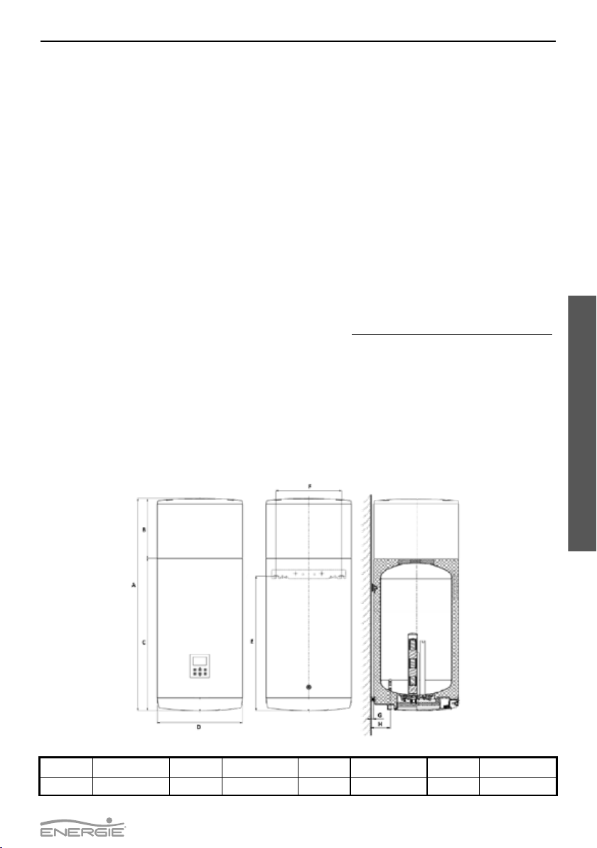
2.1. Dimensions
Technical Manual
A1275 mm C855 mm E724 mm G15 mm
B420 mm D520 mm F450 mm H115 mm

38
ECO100
English
2.2. Components
1Top Cover (thermodynamic block) 9Safety thermostat
2Outer Casing (External Sheet) 10 Ceramic resistance
3Polyurethane Insulation 11 Magnesium Anode
4Enamelled Cylinder 12 Display
5Hot water outlet 13 Electrical resistance sheath
6Temperature Sensor 14 Condenser
7Cold water inlet 15 Solar Panel connections
8Electrical connections protection
Technical Manual
39
ECO100
English
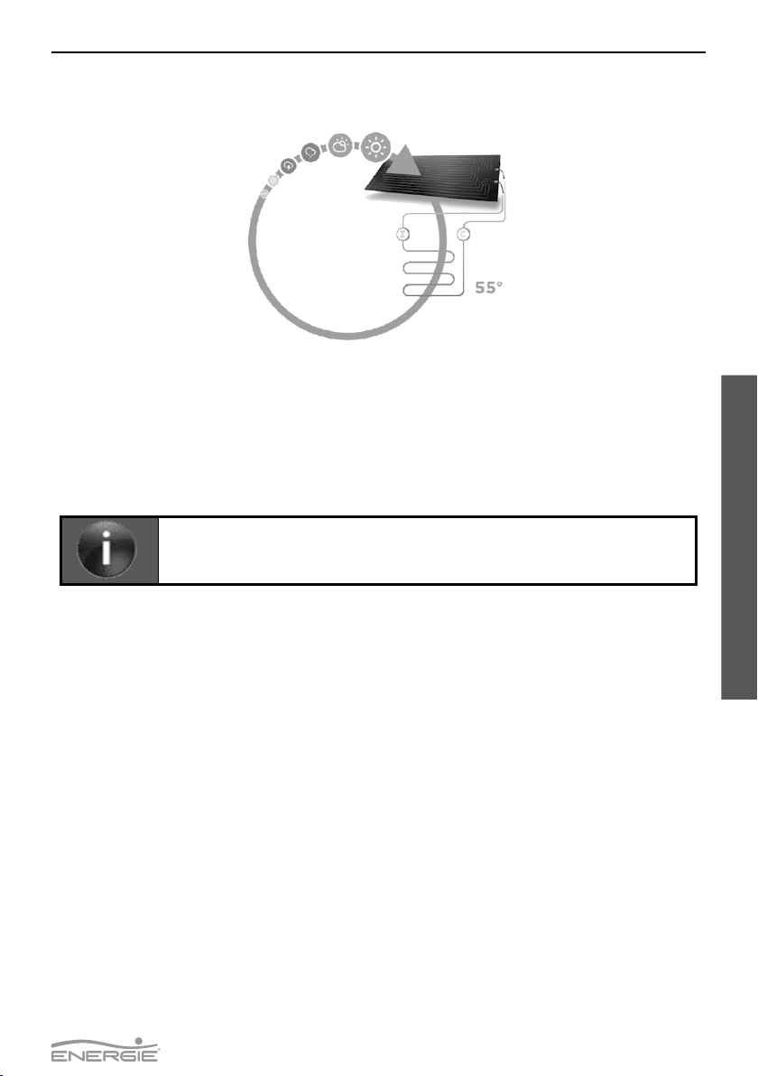
2.3. Running principle
Technical Manual
1. The cooling uid (R134a) is compressed in the high ecient compressor, raising its pressure and tem-
perature;
2. In the condenser (not in direct contact with the water), the heat energy in the cooling uid is transmit-
ted to the water in the water storage heater;
3. The condensate uid (high pressure) runs from the expansion valve which is responsible for easing
the its pressure;
4. The uid absorbs heat energy from the environment through the passage through the thermodynamic
solar panel (evaporator)
The R134a is a HFC coolant, thus not harmful to the ozone layer. It has great chemi-
cal and thermal stability, low toxicity, non-inammable, and is compatible with most
materials.
40
ECO100
English
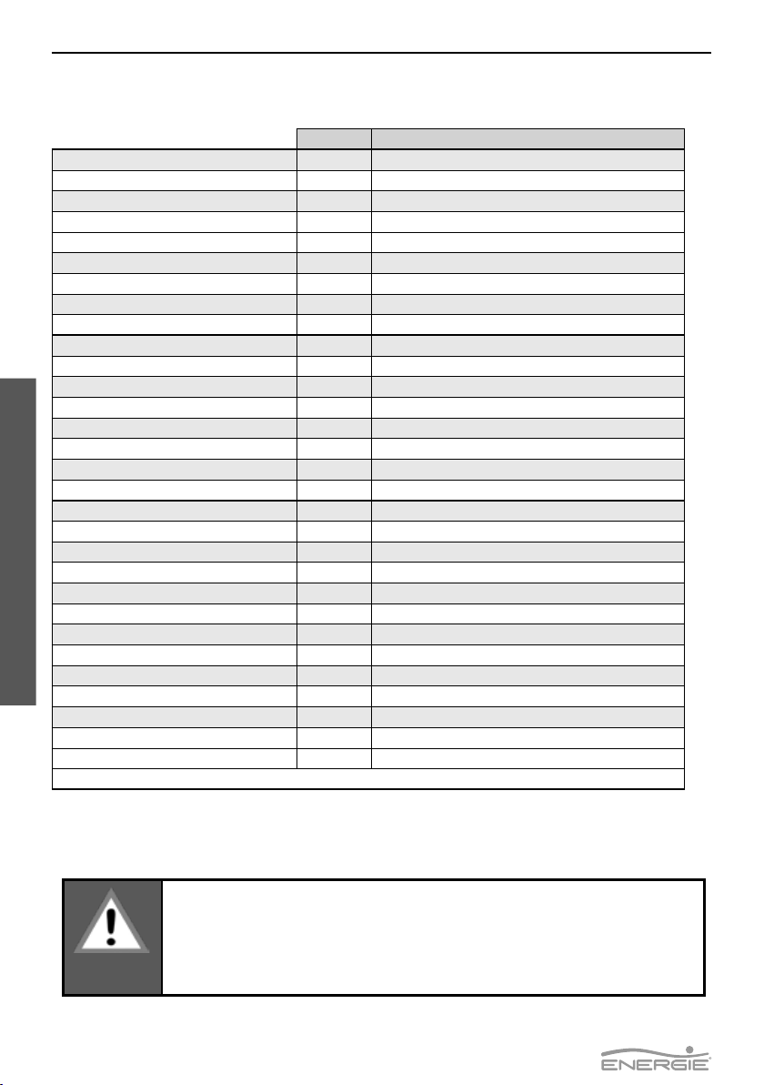
2.4. Technical Data
Unit. ECO100
Equipment type Thermodynamic Solar System for DHW
Tank Rated Capacity L 100
Weight Empty Kg. 65
Cylinder Material - Enamelled Steel
Outer Casing - Metal Sheet
Insulation - High Density Polyurethane 50mm
Corrosion Protection - Yes (Magnesium Anode)
Maximum Water Temperature 0C 80
Maximum Operating Pressure bar 7
Pressure Test bar 10
Heat Loss kWh/24h 0,95
Protection - IPX1
Electric Supply - 220-240 V / single phase / 50 Hz
Electrical Power HP (med / max) W350/600
Electrical Element W 1000
Thermal power HP W1250 | 2100
Fan Power W65
Maximum Operating A3,2 + 4,4 (with electrical element)
Max Temperature DWH (HP) 0C 55
Max Temperature DWH (Backup) 0C70
Fluid -/kg R 134a / 1,1
Tapping Prole - M
COP1- 2,8
Heating Time1) (HH:mm) 03:45
Max. Water in Single Intake 40 °C1) L 120
Energy Class - ErP1) - A+
Energy Eciency1) % 108
Annual Energy Consumption1) kWh/year 474
Outside Air Temperature (Min/Max) 0C-5/40
Indoor Sound Level dB(A) 51
1) A20/W10-54, according EN16147 and delegated regulations (EU) Nº812/2013
3. TRANSPORT
Transporting the equipment must be carried out with an inclination below 45
0
;
The equipment must be raised and lowered with extreme care to avoid impact that
could damage the material;
Make sure the belts and/or transportation straps do not damage the material;
Always use means of transportation suitable for the equipment (pallet lift, forklift,
etc…);
WARNING
Technical Manual
41
ECO100
English
The equipment must be transported in its original package to the place of installation. Check, before begin-
ning transport of the external unit, if the path you will travel is unobstructed, in order to prevent collisions
that could cause damage to the device.
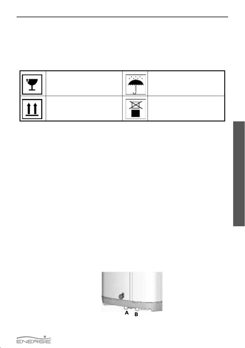
The packages contain the following information symbols:
Fragile, handle with extreme caution Keep the package dry
Make sure the arrows are always up Do not stack packages
4. INSTALLATION
Technical Manual
4.1. Safety Device
4.1.1. Pressure gauge of high/low pressure
In case of running outside the range of pressures recommended and dened by the supplier, the equip-
ment will switch o and indicate error in the electronic panel.
4.1.2. Safety Thermostat
The safety thermostat is set by the supplier to ensure that the water temperature in the storage water
heater does not exceed the standard value. Should the temperature exceed this value, the thermostat
switches o the support resistance. Switching on is done manually by qualied sta, after analyzing the
reasons for the switch o.
4.1.3. Corrosion Protection
The storage water heater is Enamelled. Besides being resistant to corrosion, the storage water heater
has in addition a magnesium anode that should be checked periodically according to information by the
installer.
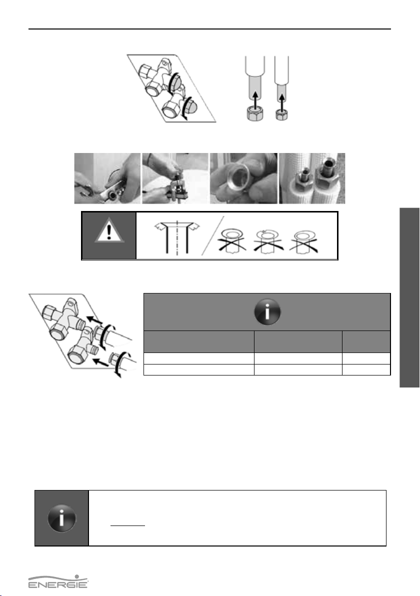
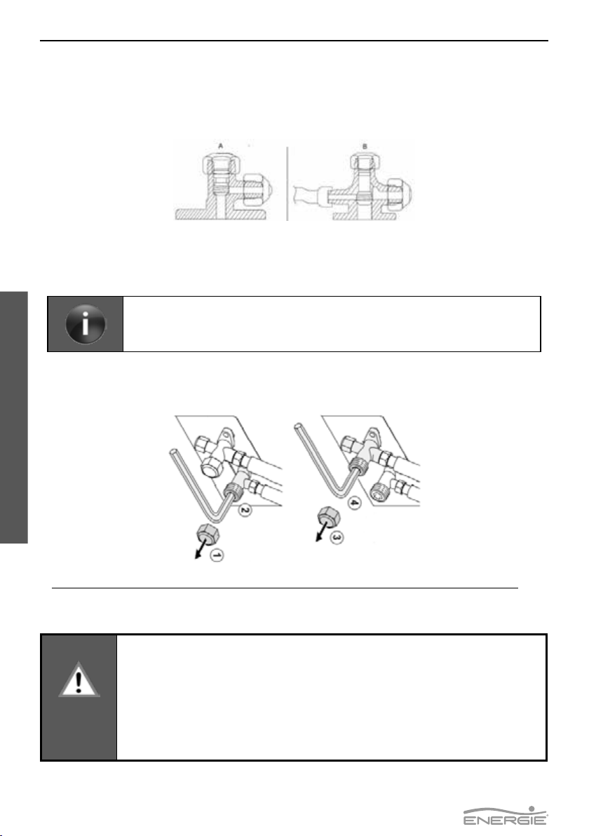
4.1.4. Dielectric Joint
Your equipment contains two dielectric joint. Its installation is considered mandatory for the correct func-
tioning. These joints prevent electron exchange between the pipes of water inlet and outlet and the sto-
rage water heater itself. This creates further protection against corrosion that could take place between
these points (A and B).
42
ECO100
English
Technical Manual
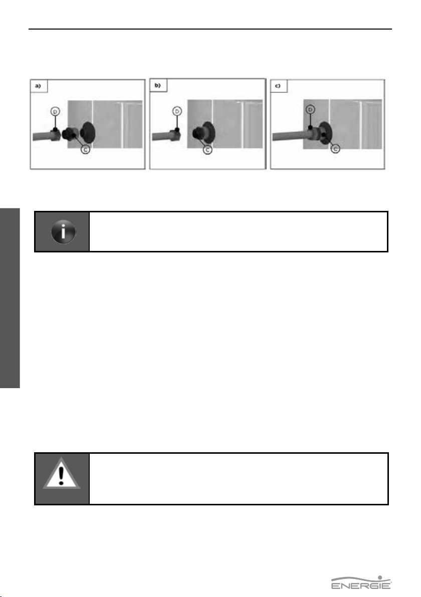
So the installer must tighten the joints (C) in the water inlet and outlet, be fore attaching the piping (D),
as demonstrated in the following sequence:
4.1.5. Expansion Vessel*
he expansion vessel is a device whose purpose is to compensate for the increase in water volume due to
temperature rise.
Installing this device is recommended procedure for a correct installation of the
equipment.
Installing this device is the responsibility of the installer.
As a general rule it is installed in the cold water pipe.
4.1.6. Safety Device*
OThe safety device allows the system to be protected against anomaly situations: cold water supply, hot
water owing back, em tying the storage water heater and high pressure. The valve is calibrated to acti-
vate at 0.7 Mpa.
In order to drain the water in the storage water heater, you should close the supply valve and open the
discharge valve.
The safety valve discharge pipe must be open into the atmosphere, because the va ve may drip water or
even discharge water.
4.1.7. Pressure Reducing Valve*
The pressure reducing valve must always be installed upstream from the safety device, and ready to acti-
vate in situations when the pressure in the circuit exceeds 3 bar (0,3MPa). This valve comes with a pressure
gauge.
*Components not supplied by the manufacturer, the installation is the responsibility of the installer
4.2. Positioning The Unit
Before starting the equipment assembly check out the wall’s carrying capacity and
what kind of material is it made, considering the equipment’s weight when loaded
with water.
WARNING
When placing the equipment in its position, bear in mind possible future interventions. To avoid having
too much space around the equipment, the magnesium anode is found on the front side of the water
storage heater.
Make sure that there is at least the following free space around the equipment.

43
ECO100
English
Technical Manual
Adjust the hut in the back of the equipment so you can assure the minimum tilt of 1 degree backwards.
4.3. Attachment of Panel
The nature of the site and the inclination angle where the panels are installed are important factors to take
into account. In order to benet the most from the sunlight exposure, the panels should have a pitch be-
tween 100 and 850 relative to the horizontal plane, and preferably oriented to the south. The panel already
comes with 6 holes for M8 in the lateral skirts. The distance between holes in the place where the panel
rests, should coincide with the holes made in the panel.
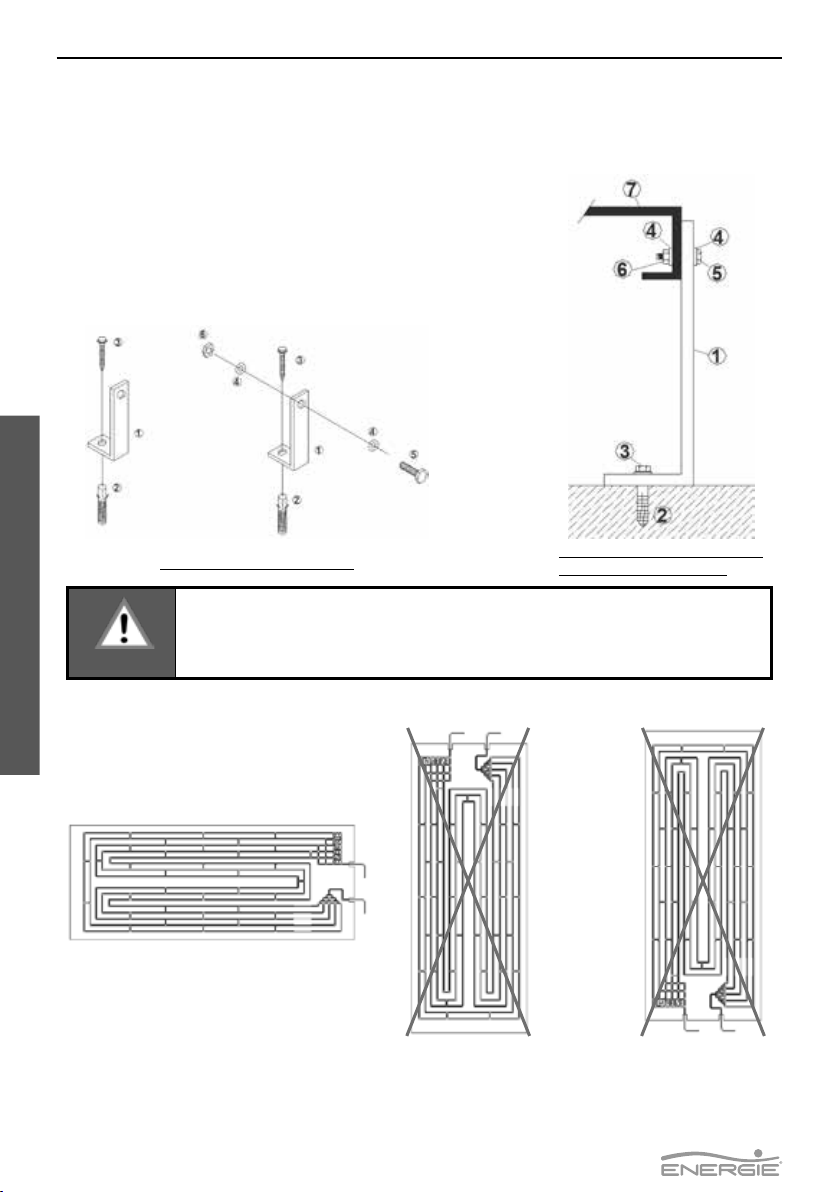
The system comes with 3 small L-shaped fastenings (side A) and 3 large L-shaped fastenings (side B) that
should be attached as depicted in the picture. The desired pitch of the panel should be adjusted.painel.
44
ECO100
English
Technical Manual
The prole should be attached to the base (e.g. rooftile) through a plastic bushing and a self-thread M6
bolt which have been supplied.
The attachment of the panel to the L-shaped fastenings is done through M6 bolts and its females and
washers.
Attachment of L-shaped Attachment of L-shaped
fastenings and panel:
WARNING
The panel must be installed facing down, the connections must be turned down.
A - Liquid inlet
B - Vapour outlet (suction)
B
A

45
ECO100
English
Technical Manual
WARNING
The cooling uid couplings must be done by a qualied technician, with a profession-
al certicate of qualications for this purpose.
The thermodynamic unit holds a pre-load of uid R134a.
WARNING
The cooling uid couplings must be thermally insulated in order to prevent burns and
to ensure an optimal system performance.
The pipe shall be a copper pipe of the refrigeration type (Cu DHP type according to
ISO1337 standards)
DIAMETER OF THE PIPES
GAS (suction) LIQUID (panel inlet)
Nº panels Inches Inches
1 3/8’’ 1/4’’
4.4.1. Connection to the Panel
a) Prepare the copper pipe, removing the protective caps from the extremities.
b) Place the extremity of the pipe upside down, cut the appropriate size of pipe and sand the rough
edge.
c) Remove the females from the couplings in the panes and insert them in the pipe.
4.4.Refrigerant Connections

46
ECO100
English
Technical Manual
d) Flange the pipe with the appropriate tool shaping a conic edge, make sure that there are
no rough edges or imperfections and that the vertical of the walls is uniform.
1) 2)
WARNING
The cooling uid couplings must be thermally insulated in order to prevent burns and
to ensure an optimal system performance.
WARNING
e) Tighten the female coupling with your hands, turning it a few times.
e2
e1e3
Diameter of the Pipe (inches) Applied Torque (Nm) Wrench nº
1/4” 14 a 16 19
3/8” 33 a 42 21
4.4.2. Connection of the Thermodynamic Block
a) Cut the required measure of the pipe with the edge turned upside down. Sand any re-
maining rough edges;
b) Remove the female nuts from the 2-way and 3-way valve connections and place them
in the tubes
47
ECO100
English
Technical Manual
c) Flange the tube with the appropriate tool, forming the conical, taking care that it should
not have burrs or imperfections and the length of the walls should be uniform.
WARNING
d) Tighten the tubes to the respective valves. It is recommended to use a thread sealant on
all existing threaded connections.
Diameter of the Pipe (inches) Diameter of the nut
(mm) Torque (N.m)
1/4” 17 14-18
3/8” 22 34-42
4.4.3. Load of Nitrogen
a) After nishing the couplings, make sure there are no leaks. For this purpose, inject a load
of nitrogen with a pressure of 10 bar through the pressure inlet (3-way valve).
b) Brush every coupling in soap foam and make sure that the pressure in the pressure
gauge is constant;
c) After checking the leaks remove the nitrogen from the circuit.
4.4.4. Vacuum
• During the whole procedure, employ, connections, vacuum pump and pressure
gauges suitable for uid R134a.
• Employ a vacuum pump only to remove the air and humidity inside the piping.
• Never use the system coolant to purge the connection pipes.
• The valves must be completely shut during the vacuum process, in order to
create vacuum only in the piping.
48
ECO100
English
Technical Manual
a) Create a vacuum with the vacuum pump plugged to the inlet of the 3-way pressure valve
as depicted, keeping the valves completely shut until a vacuum of 50 Pa (0,5mbar);
Shut Valves
A – 2-Way Valve B – 3-Way Valve
b) Once the vacuum procedure is over, shut the vacuum pump valves. The vacuum pressure
gauge should indicate the same reading after the pump has stopped, ensuring the installa-
tion is in a vacuum and ready for running the coolant;
After concluding the vacuum, do not remove the hoses while the system is not com-
pletely pressurized by the coolant.
c) After concluding the vacuum procedure you must open the two valves so that the cool-
ant may circulate throughout the whole system.
First open the two-way valve, after equalizing the pressure open the three-way valve.
4.5. Hydraulic Couplings
WARNING
• It is necessary to install a safety group in the cold water inlet of the appliance.
The safety device shall comply with EN 1487: 2002, maximum pressure 7 bar (0,7
MPa). The passage of the water from the safety unit to the tank must never be
prevented by any other accessory
• The safety unit must be connected by tubing with a diameter never lower than
the connection of the cold water inlet. The discharge part shall be connected to
a sewage trap or, if this is not possible, raise to at least 20mm from the oor to
allow visual inspection;
• In order to avoid high pressures in the water supply through the network, a pres-
sure reducing valve calibrated to 3 bar (0.3 MPa) must be installed.
49
ECO100
English
Technical Manual
The Manufacturer is not responsible for damage related to not following these rec-
ommendations / warnings.
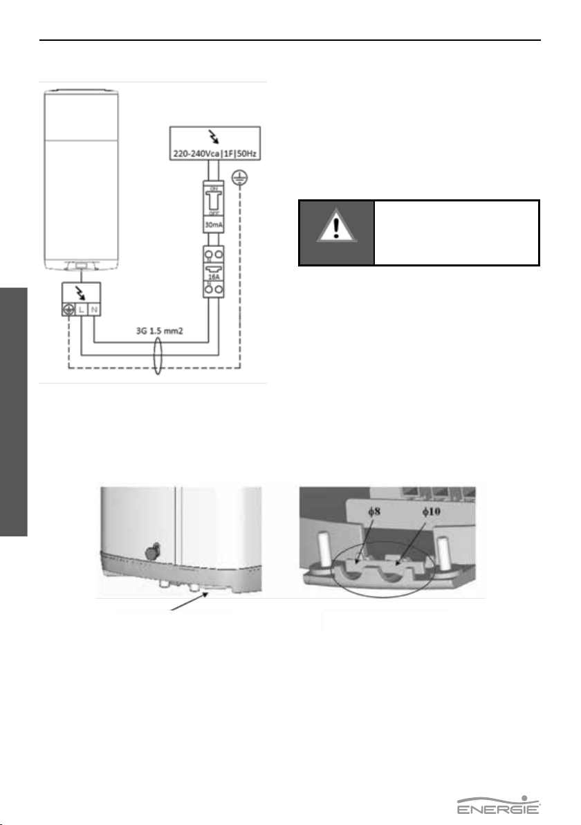
Description Cable Type Protection
Power cable 3G 1.5 mm2 H05VV-F
- Bipolar circuit-breaker 16A;
- Protection dierential circuit
breaker of30 mA;
The device is supplied with a power cable.
It is advisable to check the electrical installation for compliance with current regulations.
Make sure that the installation is suitable for the maximum power absorbed by the Ther-
modynamic System (see plate data), both in the cable section and in compliance with the
regulations in force.
Multiple outlets, extension cords and adapters are prohibited. Grounding is mandatory. It
is forbidden to use the pipes of the water, heating or gas system to ground the appliance.
Before starting up for the rst time, make sure that the mains voltage corresponds to the
rating of the appliance. The manufacturer of the appliance can not be held liable for any
damage caused by the failure of the system to ground or by an anomaly in the power sup-
ply.
To disconnect the appliance from the mains, a bipolar switch must be used in accordance
with current CEI-EN standards (contact opening of at least 3 mm, better if equipped with
fuses). The connection of the appliance must comply with European and national standards
and must be protected with a 30 mA dierential switch.
4.6. Electric Connections
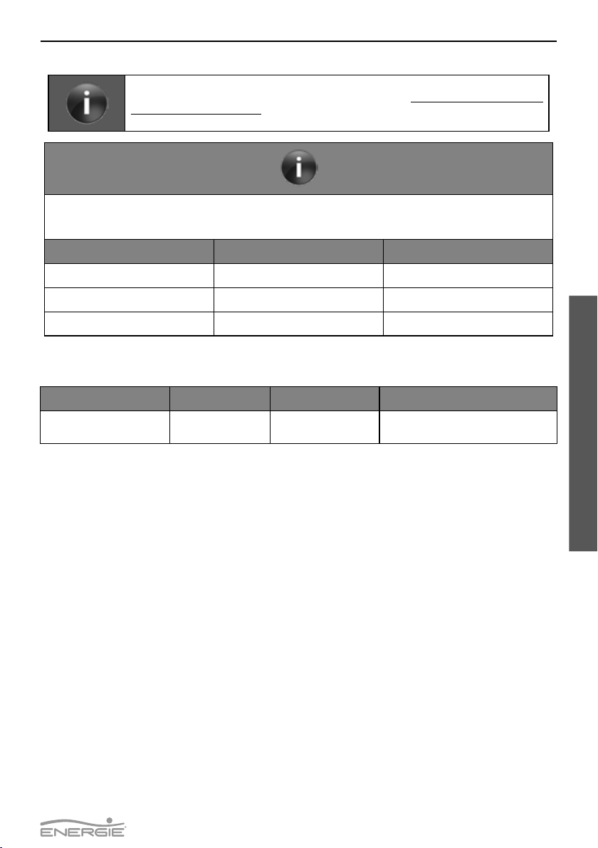
The water you use may contain impurities and/or substances damaging to the system and even harm-
ful to your health. Make sure you use water with quality tting for home consumption. The following
table indicates some parameters according to which water must be subjected to chemical treatment.
Hardness(
0
dH) pH Treatment
3,0 up to 20,0 6,5 up to 8,5 Não
3,0 up to 20,0 <6,5 up to >8,5 Sim
<3,0 or >20,0 ----------------- Sim
50
ECO100
English
Technical Manual
If the power supply cable is damaged, it must be replaced by the manufacturer, by its custom-
er service, or by sta with similar training.
To replace the power cable, must the protection cover located under the equipment be re-
moved.
WARNING
Before undertaking any
maintenance operation on the
equipment, make sure it is not
plugged to the power supply!
Protection cover Cable gland
Table of contents
Other Energie Inverter manuals


Popular Inverter manuals by other brands

PowerStar
PowerStar LW Series Product information guide

Mitsubishi Electric
Mitsubishi Electric F700 instruction manual

Lenze
Lenze 8200 series operating instructions

Comnet
Comnet netwave NWKSP2 Installation and operation manual

Fischer Panda
Fischer Panda 6500 PMS manual

Growatt
Growatt 750-S Installation & operation manual


SMA
SMA MEDIUM VOLTAGE POWER STATION 630SC-JP Transportation and Installation Requirements

Solectria Renewables
Solectria Renewables PVI 20TL Installation and operation manual

INVT
INVT Goodrive 300 Operation manual

Sungrow
Sungrow SH3.0RS user manual

SMA
SMA SUNNY ISLAND 4.4M operating manual

Sunfar
Sunfar V260-4T0007G/4T0011P user manual