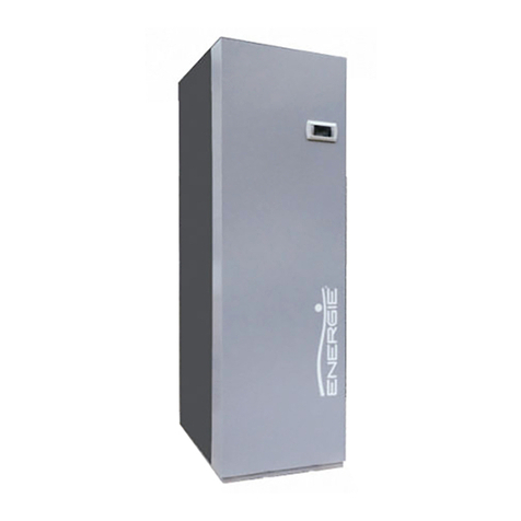
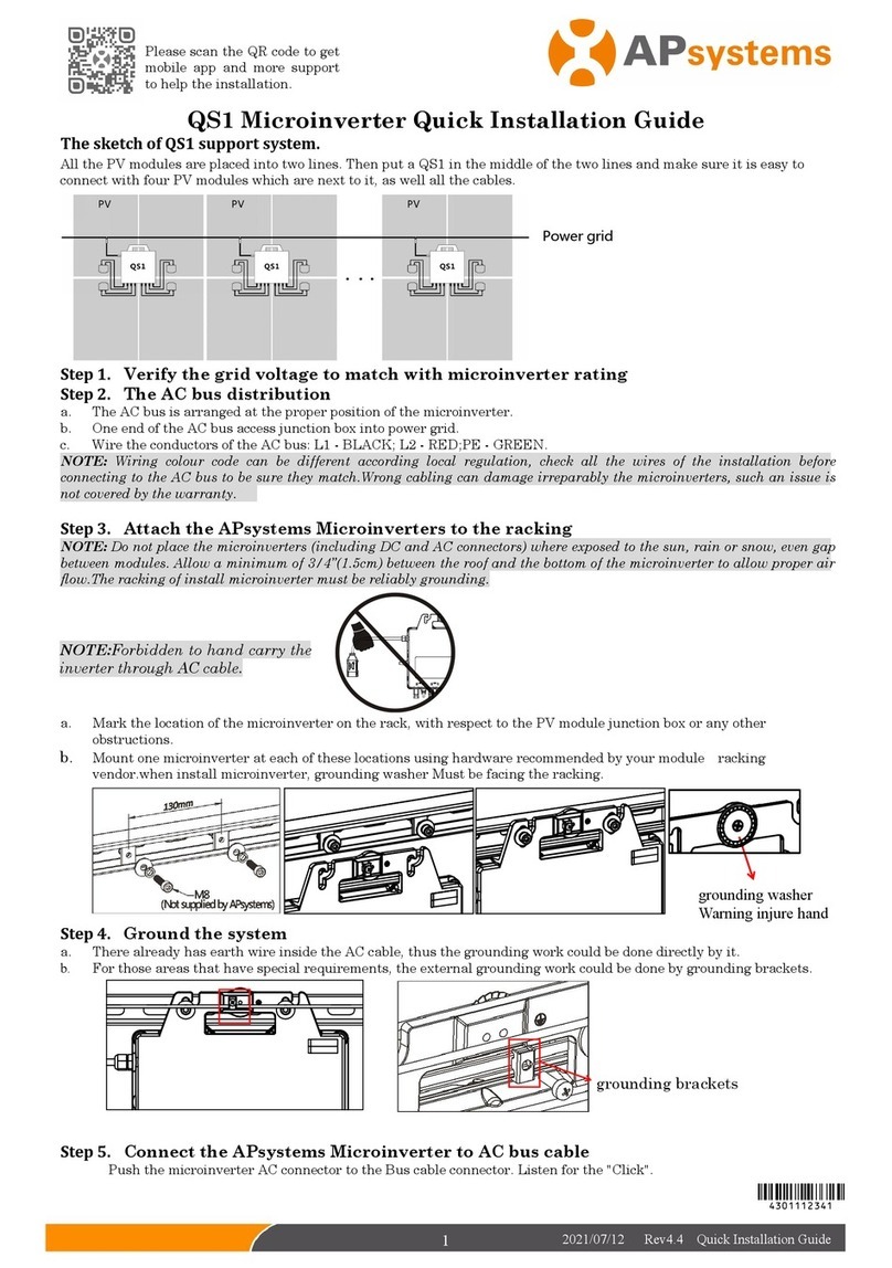
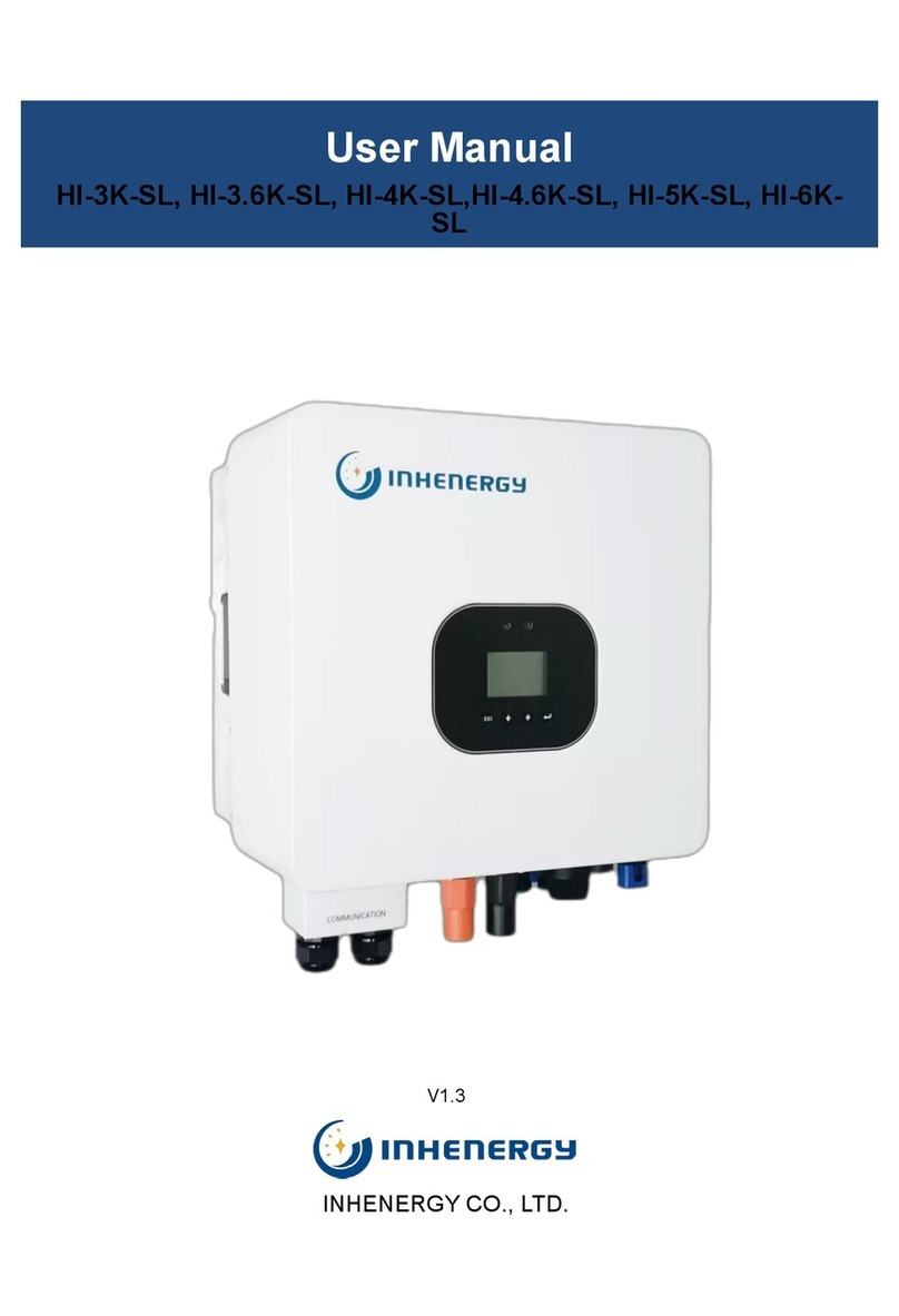
Energie Eco User manual

EN TECHNICAL MANUAL
200esm | 250esm | 300esm
300esms
250i | 300i |250is | 300is |500is
250ix | 300ix
250isx | 300isx | 500isx
Review 13
Version 0
Date 09/01/2020
Directives
2006/95/CE
European Certification
EN 60335-1
EN 60335-2-21
EN 60335-2-40
ECO


3
ECO
Esteemed Client,
We would like to thank you for your choice when you acquired an
equipment for sanitary water heating.
The thermodynamic solar system ECO will surely meet all your expec-
tations and provide many years of comfort with maximum power sav-
ing.
Our organization dedicates much time, energy and economic resourc-
es in order to develop innovations that will promote power saving in
our products.
Your choice has demonstrated your good sense and concern with pow-
er consumption, a matter that aects the environment.
We have taken on a permanent commitment to conceive innovative
and ecient products so that this rational use of energy can actively
contribute to the preservation of the environment and natural resourc-
es of the planet.
Keep this manual whose objective is to inform, alert and advise about
the use and maintenance of this equipment.
Our services are always at your disposal. Feel free to call upon us!
Technical Manual
English

4
ECO
INDEX
1.IMPORTANT.................................................................................................................
1.1. Symbols .......................................................................................................................
1.2 Pre-installation Information .................................................................................
1.3 Safety information ...................................................................................................
2.PACKAGE .......................................................................................................................
2.1. Contents .......................................................................................................................
2.2. Transpor ......................................................................................................................
3.SPECIFICATIONS ...........................................................................................................
3.1. Running principle ..................................................................................................
3.2. Technical features ...................................................................................................
3.3. Technical features ...................................................................................................
3.4. Main Components ...................................................................................................
3.4.1. General diagram of assembly .................................................................
3.4.2. Thermodynamic Solar Panel ..................................................................
3.4.3. Storage Water Heater ...............................................................................
3.4.4. Thermodynamic Block .............................................................................
3.4.5. Cooling Fluid .................................................................................................
3.5. Safety and Control Devices ...............................................................................
3.5.1. Pressure gauge of high/low pressure .................................................
3.5.2. Safety Thermostat ......................................................................................
3.5.3. Temperature Sensor ...................................................................................
3.5.4. Protection against corrosion .................................................................
3.5.5. Bipolar Socket ...............................................................................................
3.5.6. Expansion Vessel .........................................................................................
3.5.7. Safety Device .................................................................................................
3.5.8. Pressure Reducing Valve .........................................................................
4.INSTALATION ............................................................................................................
4.1. AttachmentofPanel................................................................................................
4.2.Set-upoftheStorageWaterHeater......................................................................
4.3. InstallationofThermodynamicBlock................................................................
4.4. RefrigerantConnections........................................................................................
4.4.1. Connection to the Panel (x1) .....................................................................
4.4.2. ConnectiontothePanels(x2)....................................................................
6
6
6
6
7
7
8
9
9
10
11
12
12
13
14
17
18
18
18
18
18
18
18
19
19
20
20
20
22
22
23
23
24
Technical Manual
English

5
ECO
English
4.4.3. Connection of Thermodynamic Block and Storage Water
Heater ............................................................................................................................
4.4.4. Connection of Thermodynamic Block and Thermodynamic
Panel ..............................................................................................................................
4.4.5. Load of Nitrogen .........................................................................................
4.4.6. Create Vacuum ............................................................................................
4.4.7 Load of Complementary Cooling Fluid .............................................
4.4.8. Checking good running condition .....................................................
4.5. Hydraulic Couplings ..............................................................................................
4.6. Electric Connections ............................................................................................
5.FIRST USE .........................................................................................................................
5.1. Filling the tank ..........................................................................................................
5.2. Start-up of the System .........................................................................................
6.SYSTEM OPERATION .................................................................................................
6.1. Control Panel ..............................................................................................................
6.2. Keys (Functions) ....................................................................................................
6.3. Description ................................................................................................................
6.4. Symbols ......................................................................................................................
6.5. Operating Modes ....................................................................................................
6.5.1. ECO Operating Mode ................................................................................
6.5.2. AUTO Operating Mode .............................................................................
6.5.3. BOOST Operating Mode .........................................................................
6.6. Extra Functions .......................................................................................................
6.6.1. DISINFECT Function ..................................................................................
6.6.2. HOLIDAYS Function ..................................................................................
6.6.3. PVFunction ....................................................................................................
7.SYSTEM MENU ...............................................................................................................
8.PARAMETERS DESCRIPTION .................................................................................
9.TABLE OF ERRORS .....................................................................................................
10.GRAPHIC OF PROBES ..............................................................................................
11.RESOLUTION OF PROBLEMS ................................................................................
12.SYSTEM MAINTENANCE .........................................................................................
12.1. General Inspection ...............................................................................................
12.2. Magnesium Anode ...............................................................................................
12.3. Cleaning Filter of Throttle Valve .....................................................................
12.4. Safety Thermostat ................................................................................................
12.5. Empty the Storage Water Heater ................................................................
25
26
27
27
28
28
28
29
32
32
32
33
33
33
34
34
35
35
35
35
36
36
36
36
37
38
39
39
40
42
42
42
42
42
43
Technical Manual

6
ECO
1. IMPORTANT
1.1. Symbols
Every process that the suppli-
er believes to be conducive to
harmful danger and/or material
damage, will be signalled with a
danger sign.
For a better characterization of
the danger, the symbol will be
followed by one of these words:
• DANGER: when there is the
possibility of harm to the op-
erator and/or people in the
vicinity of the equipment.
• WARNING: when there is
the possibility of material
damage to the equipment
and/or attached materials.
All the information that the sup-
plier believes to be an asset for
better performance and pres-
ervation of the equipment, will
be signalled together with the
information sign.
1.2 . Pre-installation Information
1.3 . Safety information
WARNING / DANGER
The electrical installation of the equipment
must comply with the national regulations
for electrical installations in eect.
ECO will only operate after receiving its
load of coolant.
The maximum water pressure into the hy-
draulic circuit inlet is 0.3 Mpa and the min-
imum pressure is 0.1 MPa.
The power supply is 230 V, 50 Hz, and the
power supply cable is plugged into a sock-
et with earth wiring.
If the power supply cable is damaged, it
must be replaced by the manufacturer, by
its customer service, or by sta with similar
training in order to avoid any danger.
ECO will only operate if the storage water
heater is lled with water.
This device can be used by 8
year old children and older, or
people with physical, sensorial
or mental handicaps, or lacking
experience / knowledge, if they
received training regarding the
running of the device in a safe
way and are aware of the dan-
gers involved.
Children must not play with the
appliance.
DANGER
When installing:
• The installation of a thermodynamic
equipment for heating sanitary wa-
ter must be carried out by sta with
suitable training and qualied for
this purpose;
• The device should not be installed in
places that present a risk of impact,
shock or explosion;
• Keep the equipment packed until
you reach the place and moment of
installation;
• Make sure all hydraulic couplings are
watertight before connecting the
equipment to the power supply.
Maintenance of the equipment:
• Equipment maintenance should be
carried out by customer service, ex-
cept operations of general and con-
tinuous cleaning which could/should
be carried out by the user;
Technical Manual
English

7
ECO
• Power supply to the equipment
must be disconnected when doing
maintenance operations;
• The supplier recommends at least
one annual inspection to the equip-
ment, by a qualied technician;
• Cleaning and maintenance must not
be carried out by children unless
they are under supervision.
High pressure and temperature:
• The principle for running this equip-
ment is directly linked to high tem-
perature and pressure; thus, the
processes that imply contact with
the equipment must be thought out
with caution to prevent the risk of
burns and projection of material.
Cooling Fluid:
• The cooling uid employed in the
whole process is R134a, CFC-free,
non-inammable and without harm-
ful eects for the ozone layer;
• However, according to the law, the
uid in this equipment cannot be re-
leased into the environment;
• Handling of the uid in the equip-
ment must be carried out by a quali-
ed technician.
Information for the Client:
• The Installer must inform the client
about the running of the equipment,
its dangers, rights and duties of the
client.
2. PACKAGE
2.1. Contents
The equipment is supplied in three packages, one for the thermodynamic panel and its
attachment elements, one for the storage water heater and another for the thermodynamic
block together with the hood and elements to attach to the storage water heater.
The packages contain:
I. Thermodynamic panel + its attachment ele-
ments
II. Storage Water Heater
III. Thermodynamic block + attachment ele-
ments
IV. Hood + Electronic panel
V. Installation manual and Warranty
VI. Dielectric joints (except stainless steel tank) I
II
III
IV
V
VI
Technical Manual
English

8
ECO
• Transporting the equip-
ment must be carried out
with an inclination below
45
0
;
• The equipment must be
raised and lowered with
extreme care to avoid im-
pact that could damage
the material;
• Make sure the belts and/
or transportation straps do
not damage the material;
• Always use means of trans-
portation suitable for the
equipment (pallet lift, fork-
lift, etc…);
WARNING
2.2. Transport
The equipment must be transported in its
original package to the place of installation.
Check, before beginning transport of the
external unit, if the path you will travel is
unobstructed, in order to prevent collisions
that could cause damage to the device.
The packages contain the following infor-
mation symbols:
Fragile, handle with extreme
caution
Make sure the arrows are al-
ways up
Keep the package dry
Do not stack packages
Technical Manual
English

9
ECO
3. SPECIFICATIONS
3.1. Running principle
The thermodynamic solar system ECO, is
an equipment based upon the principle of
cooling by compression – Principle of Car-
not – which we designate Thermodynamic
Solar Systems: solar panel and heat-pump.
The solar panel, the main component,
placed outside, is in charge of collecting the
energy from:
• Diuse and direct solar radiation.
• External air, by natural convection.
• The wind eect (almost invariably
available).
• Rainwater.
The temperature gradient caused by the ex-
ternal agents mentioned, ensures the klea
(ecological cooling uid) will evaporate in-
side the solar panel.
The absence of glass in the panel allows for
an increased thermal exchange by convec-
tion.
After circulation in the panel, the klea is as-
pirated by the system’s mechanical compo-
nent, the compressor, which will increase its
temperature and pressure; it is then trans-
ferred to the water circuit through a heat
exchanger.
Before the Klea returns to the solar panel it
is necessary that there should be a narrow-
ing, that is, reduce the pressure and ensure
that it is again in a liquid state, thus com-
pleting the cycle.
The easy way we combine technology with
a law of Nature (change of state of a u-
id), demonstrates the true potential of the
Thermodynamic Solar System - ECO.
Technical Manual
English

10
ECO
3.2. Technical features (x1 panel)
Technical Manual
English
Unid. 250i 300i 200esm 250esm 300esm 250ix 300ix
HOT WATER CYLINDER
Dry Weight Kg 62 74 73 83 95 69 81
Capacity Kg 250 300 200 250 300 250 300
Internal Protection - Stain. Steel Enamelled Stain. Steel
Cathodic Protection - Magnesium Anode (1”1/4 Female)
Hydraulic
Joints
Water – Inlet and Outlet
inch
3/4” Male
TP Valve 1/2” Female
Recirculation 3/4” Male 1/2” Female
Coil – Inlet and Outlet Not Applicable 1” Male
Maximum Pressure bar 7
Test Pressure bar 10
Maximum Temperature °C 80
Heat Loss (EN 12897) kWh/24h 1,01 1,17 1,04 1,2 1,39 1,01 1,17
Exchanger Output Power1kW Not Applicable a)30,0; b)18,0
THERMODINAMIC
SOLAR PANEL
Material - Solokote Anodized Aluminium
Dimensions (L x W x H) mm 2000 x 800 x 20
Weight kg 8
Max. working pressure bar 12
Test pressure bar 15
Max. exposure temp. °C 120
Min. running temperature °C - 5
Min. exposure temp. °C - 40
THERMODYNAMIC
BLOCK
Width / Height / Depth mm 320 / 710 / 280
Weight kg 17,5
Absorbed power (Med/Max) W 390 - 550
Thermal power (Med/Max) W 1690 / 2900
Electrical Backup Power W 1500
Compressor Type - Hermetic
Compressor Noise Level dB 39
Refrigerant / Qt.2- / g R134a / 11002
Piping Material - Copper (DHP ISO1337)
Line (Liq. | Asp.) inch 1/4” | 3/8”
Power Supply V / Hz 230 Monophase / 50
Fuse (Main | Elect. Heater) A 10 | 10
Performance
Performance
Coecient
(COP) 3
EN 255 – 3 (air 7 °C / air 20 °C) 3,4 / 4,6 3,3 / 4,5 3,4 / 4,6
EN 16147 (air 7 °C) 2,9 3,0 2,8 2,9 3,0 2,9 3,0
Amount of Useful Water at 40 °C lts 349 389 247 349 389 342 382
1. a) Primary (Tin=90 °C; Tout=80 °C); Production DHW (Tin=10 °C; Tout=60 °C)
b) Primary (Tin=70 °C; Tout=60 °C); Production DHW (Tin=10 °C; Tout=60 °C)
2. The amount of uid must be checked by the installer. In some cases it is necessary to add
or remove uid in order to ensure the correct running of the system.
3. Water temperature from 10 °C to 54 °C

11
ECO
3.3. Technical features (2x panels)
Technical Manual
English
Unid. 250is 300is 300esms 250isx 300isx 500is 500isx
HOT WATER CYLINDER
Dry Weight Kg 62 74 95 69 81 110 121
Capacity Kg 250 300 300 250 300 455 455
Internal Protection - Stain. Steel Enamelled Stain. Steel
Cathodic Protection - Magnesium Anode (1”1/4 Female)
Hydraulic
Joints
Inlet / Outlet
inch
3/4” Male 1” Male
TP Valve 1/2” Female
Recirculation 3/4” Male 1/2” Female 3/4” Male
Coil – Inlet and Outlet Not Applicable 1” Male N / A 1” Male
Maximum Pressure bar 7
Test Pressure bar 10
Maximum Temperature °C 80
Heat Loss (EN 12897) kWh/24h 1,01 1,17 1,39 1,01 1,17 1,81
Exchanger Output Power1kW Not Applicable a)30,0; b)18,0 N/A a)54,2;
b)32,5
THERMODINAMIC
SOLAR PANEL
Material - Solokote Anodized Aluminium
Dimensions (L x W x H) mm 2000 x 800 x 20
Weight kg 8
Max. working pressure bar 12
Test pressure bar 15
Max. exposure temp. °C 120
Min. running temperature °C - 5
Min. exposure temp. °C - 40
THERMODYNAMIC
BLOCK
Width / Height / Depth mm 320 / 710 / 280
Weight kg 20,5
Absorbed power (Med/Max) W 595 / 890
Thermal power (Med/Max) W 2800 / 4550
Electrical Backup Power W 1500 2200
Compressor Type - Hermetic
Compressor Noise Level dB 39
Refrigerant / Qt.2- / g R134a / 13002
Piping Material - Copper (DHP ISO1337)
Line (Liq. | Asp.) inch 3/8” | 1/2”
Power Supply V / Hz 230 Monophase / 50
Fuse (Main | Elect. Heater) A 10 | 10
Performance
Performance
Coecient
(COP) 3
EN 255 – 3 (air 7 °C / air 20 °C) 3,5 / 4,7
EN 16147 (air 7 °C) 2,9 3,0 3,0 2,9 3,0 3,1 3,1
Amount of Useful Water at 40 °C lts 349 389 389 342 382 599 592
1. a) Primary (Tin=90 °C; Tout=80 °C); Production DHW (Tin=10 °C; Tout=60 °C)
b) Primary (Tin=70 °C; Tout=60 °C); Production DHW (Tin=10 °C; Tout=60 °C)
2. The amount of uid must be checked by the installer. In some cases it is necessary to add
or remove uid in order to ensure the correct running of the system.
3. Water temperature from 10 °C to 54 °C

12
ECO
3.4. Main Components
3.4.1. General diagram of assembly
[1]Thermodynamic Solar Panel
[2]L-shaped fastenings for attachment of Aluminium Panel
[3]Set of bolt, female, washer and bushing (6x or 8x)
[4]Copper pipes
[5]Water storage heater
[6]Thermodynamic block
[7]Hood + Display
[8]Bolts CHC M8
[9]Expansion tank
[10]Safety device
[11]Pressure reduction valve
Technical Manual
English

13
ECO
3.4.2. Thermodynamic Solar Panel
The solar panel is a roll-bond type plate
manufactured in double channel pressed al-
uminium, with a post-press anodization-ox-
idation that creates a dark tone aspect.
There are two types of panels available: left
and right (designated according to side of
connections).
The panel has a standard dimension of
2000 mm x 800 mm x 20 mm.
The panel connections are Flare SAE
(threaded) type. These connections are
used only in the equipments with one panel.
• 3/8’’ Aspiration (upper part)
• 1/4’’ Liquid (lower part)
Left Panel
Right Panel
ODS (welded to panel)
3/8” are Male SAE
ODS (welded to panel)
1/4” are Male SAE
[12] Thermodynamic Solar Panel
[13] Aluminium L-shaped fastenings for attachment of Thermodynamic Panel (6x or 12x)
[14] Elements for attachment of Thermodynamic Panel
14
13
12
Technical Manual
English

14
ECO
The hot storage water heater is vertical and
rests on the oor. The tank is made of car-
bon steel with enamel coating or in stainless
steel. The thermal insulation is of expanded
polyurethane with a thickness of 40 mm.
The storage water heater has a cold water
inlet, hot water outlet, AQS return and an
outlet for the expansion valve.
[14] Hood of ECO
[15] Condenser / Coil
[16] “One-Shot” Female Valve
[17] “One-Shot” Male Valve
[18] Temperature Probe + Safety Thermostat
[19] Resistance
[20] Display
[21] External Sheet
[22] Magnesium Anode
[23] Tank
[24] Polyurethane Insulation
It also comes equipped with a magnesium
anode positioned at the bottom at 450.
There is in the central part of the storage
tank an opening for placing the backing re-
sistance, as well as a safety thermostat and
temperature probe.
[25] Adjustable support foot
[26] Cold water inlet
[27] Recirculation
[28] TPR Valve
[29] Hot water outlet
3.4.3. Storage Water Heater
Technical Manual
English
14
15
16
17
18
19
20
21
22
23 24
25
26
27
22
28
29

15
ECO
Seal with features
[A] Model
[B] Production number
[C] Serial number
[D] Production date
[E] Volume
[F] Weight
[G] Downstream pressure of pressure throttle valve
[H] Upstream Maximum Pressure of pressure throttle valve
[I] Maximum pressure in Storage Water Heater
[J] Maximum Temperature in Storage Water Heater
[L] Recommended Temperature in Storage Water Heater
Technical Manual
English

16
ECO
Dimensions of Storage Water Heater
Technical Manual
English
ECO 500 i | ix
ECO200esm / 250esm | i | ix
ECO 300esm | i | ix

17
ECO
We call Thermodynamic Block to the equip-
ment set on a galvanized steel structure,
that contains two of the main elements for
running the thermodynamic cycle: com-
pressor and expansion valve.
The lateral section of the block has two
valves of 2 and 3 ways conceived for con-
necting to the panel (3/8’’- Aspiration; 1/4’’-
[30] 3-Way Valve (Aspiration)
[31] 2-Way Valve (Liquid)
[32] Electric / Electronic circuit
box
[33] Liquid Tank
[34] Support structure for Ther-
modynamic Block
[35] Compressor
[36] Expansion Valve
[37] “One-Shot” Female Valve
[38] “One-Shot” Male Valve
Liquid). The structure where the Thermody-
namic Block rests is attached to the storage
water heater through three M8 bolts.
The thermodynamic block is also connect-
ed to the condenser / coil that surrounds
the storage water heater through two “One-
Shot” valves.
3.4.4. Thermodynamic Block
Technical Manual
English
30
31
32
33
34
35
36
37 38
Version A B C D E F G H I J L K
250i 89mm 830mm 1333mm 1465mm 580mm 880mm 1543mm 370mm 765mm ---------- --------- 1015
300i 92mm 772mm 1172mm 1315mm 650mm 950mm 1415mm 370mm 765mm ---------- --------- 1086
200esm 91mm 830mm 1161mm 1289mm 580mm 880mm 1364mm 370mm 765mm ---------- --------- 1015
250esm 89mm 830mm 1341mm 1467mm 580mm 880mm 1543mm 370mm 765mm ---------- --------- 1015
300esm 92mm 772mm 1172mm 1315mm 650mm 950mm 1415mm 370mm 765mm ---------- --------- 1086
250ix 89mm 830mm 1333mm 1465mm 580mm 880mm 1543mm 370mm 765mm 696mm 205mm 1015
300ix 92mm 772mm 1172mm 1315mm 650mm 950mm 1415mm 370mm 765mm 621mm 221mm 1154
500is 92mm 772mm 1760mm 1927mm 650mm 950mm 1995mm 370mm 765mm ---------- ---------- 1083
500isx 92mm 772mm 1760mm 1927mm 650mm 950mm 1995mm 370mm 765mm 1515mm 625mm 1083

18
ECO
3.5. Safety and Control Devices
3.5.1. Pressure gauge of high/low
pressure
In case of running outside the range of
pressures recommended and dened by
the supplier, the equipment will switch o
and indicate error in the electronic panel.
3.5.2. Safety Thermostat
The safety thermostat is set by the suppli-
er to ensure that the water temperature in
the storage water heater does not exceed
the standard value. Should the temperature
exceed this value, the thermostat switches
o the support resistance. Switching on is
done manually by qualied sta, after ana-
lysing the reasons for the switch o.
3.5.3. Temperature Sensor
The temperature sensor has the purpose
of measuring the values of temperature of
water in the storage water heater in order
to control the thermodynamic solar system.
The R134a is a HFC coolant, thus not harm-
ful to the ozone layer. It has great chemical
and thermal stability, low toxicity, non-in-
ammable, and is compatible with most
materials.
The following graphic depicts the behaviour
of pressure according to temperature vari-
ation.
3.4.5. Cooling Fluid
B
A
Technical Manual
English
3.5.4. Protection against corrosion
The storage water heater in this equipment
can be of two types: Stainless steel or Enam-
elled.
Besides being resistant to corrosion, the stor-
age water heater has in addition a magnesi-
um anode that should be checked periodical-
ly according to information by the installer.
3.5.5. Dielectric Joint (except
stainless steel tank)
Your ECO equipment contains two dielectric
joint. These joints prevent electron exchange
between the pipes of water inlet and out-
let and the storage water heater itself. This
creates further protection against corrosion
that could take place between these points
(Aand B).

19
ECO
3.5.7. Safety Device
The safety device allows the system to be
protected against anomaly situations: cold
water supply, hot water owing back, em
tying the storage water heater and high
pressure. The valve is calibrated to activate
at 0.7 Mpa.
In order to drain the water in the storage
water heater, you should close the supply
valve and open the discharge valve.
The safety valve discharge pipe must be
open into the atmosphere, because the va
ve may drip water or even discharge water.
So the installer must tighten the joints (C) in
the water inlet and outlet (Aand B), be fore
attaching the piping (D), as demonstrated
in the following sequence:
3.5.6. Expansion Vessel
The expansion vessel is a device whose pur-
pose is to compensate for the increase in
water volume due to temperature rise.
A
D
C
a)
b)
c)
D
C
D
C
Installing this device is recom-
mended procedure for a correct
installation of the equipment.
Installing this device is the re-
sponsibility of the installer.
As a general rule it is installed in
the cold water pipe.
Technical Manual
English

20
ECO
Assembly sequence:
• Solar panel
• Storage water heater
• Thermodynamic block
• Cooling connection (aspiration, liquid)
• Hydraulic connections
• Electric connections
• Nitrogen load
• Vacuum
• Installation start-up
4.1. Attachment of Panel
The nature of the site and the inclination
angle where the panels are installed are im-
portant factors to take into account. In or-
der to benet the most from the sunlight
exposure, the panels should have a pitch
between 100and 850relative to the hori-
zontal plane, and preferably oriented to the
south.
The panel already comes with 6 holes for
M8 in the lateral skirts. The distance be-
tween holes in the place where the panel
rests, should coincide with the holes made
in the panel.
The safety valve must be opened regular-
ly to remove impurities and check that it is
not blocked. The discharge pipe must be
installed in a vertical position.
3.5.8. Pressure Reducing Valve
The pressure reducing valve must always be
installed upstream from the safety device,
and ready to activate in situations when the
pressure in the circuit exceeds 3 bar. This
valve comes with a pressure gauge.
4. INSTALATION
Attachment of L-shaped fastenings:
Technical Manual
English
This manual suits for next models
14
Table of contents
Other Energie Inverter manuals
Popular Inverter manuals by other brands

Solar Stik
Solar Stik PSS-G Deployment guide

SMA
SMA SUNNY BOY STORAGE 2.5 Quick reference guide

Mitsubishi Electric
Mitsubishi Electric FR-HEL-C75K instruction manual

Trace
Trace Sun Tie ST1000 Installation and operator's manual
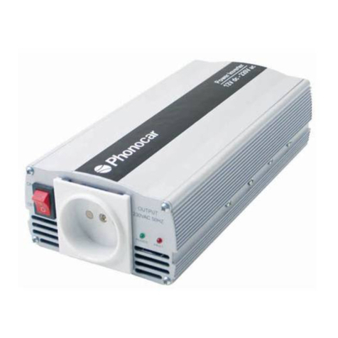
Phonocar
Phonocar 5/205 Assembling instructions

Hyundai
Hyundai HY12000LE-3 instruction manual
