CONSULT LOCAL ELECTRICAL CODES TO DETERMINE WHAT WORK MUST BE PERFORMED BY QUALIFIED ELECTRICAL SERVICE PERSONNEL.
SYMPTOM PROBLEM SOLUTION
Heater is working, but room
does not reach desired
temperature.
Breaker trips immediately
upon energizing heater.
Heater fan operates,
but does not discharge
warm air.
Heater will not shut off.
Heater discharges smoke
or emits a burnt odor.
Element heats for a moment
without the fan turning, then
immediately stops heating.
Heater does not run.
Heater continually trips
the manual reset temperature
limit control.
Troubleshooting Chart
FAULT CODES
1.Heat loss from room is greater than
heater capacity.
2.Furniture or other surfaces may be too
close to the heater.
3. Verify if temperature lock has been set.
Thermostat setpoint is 40-90 degrees.
1.Overloaded circuit.
2.A short circuit exists in the supply
or heater wiring.
3.Defective circuit breaker.
4.Thermostat malfunction.
1.Rocker switch is not set to HEAT mode.
2.Element has failed.
1.Heater continues to run at low speed
2.Heat loss from room is greater than
heater capacity.
3.Thermostat is not functioning properly.
1.Dust, lint or other matter has
accumulated inside heater.
2.Poor or loose electrical connections
1.Defective motor or internal connection.
2.Fan is jammed.
1.Thermostat is set too low.
2.Rocker switch is set to “NO HEAT”
3.Heater has tripped the manual
high-temperature reset switch.
4.Power not on at the circuit breaker.
5.Broken or poorly connected wire(s)
to heater.
6.Defective thermostat.
7.Circuit breaker not installed correctly.
1.Dust, lint or other matter has
accumulated inside heater.
2.Airflow is blocked.
3.Fan or motor is jammed.
4.None of the above.
1. Close doors and windows. Provide additional insulation, or install a higher wattage
heater or multiple heaters if necessary. (If your circuit is rated for more capacity.)
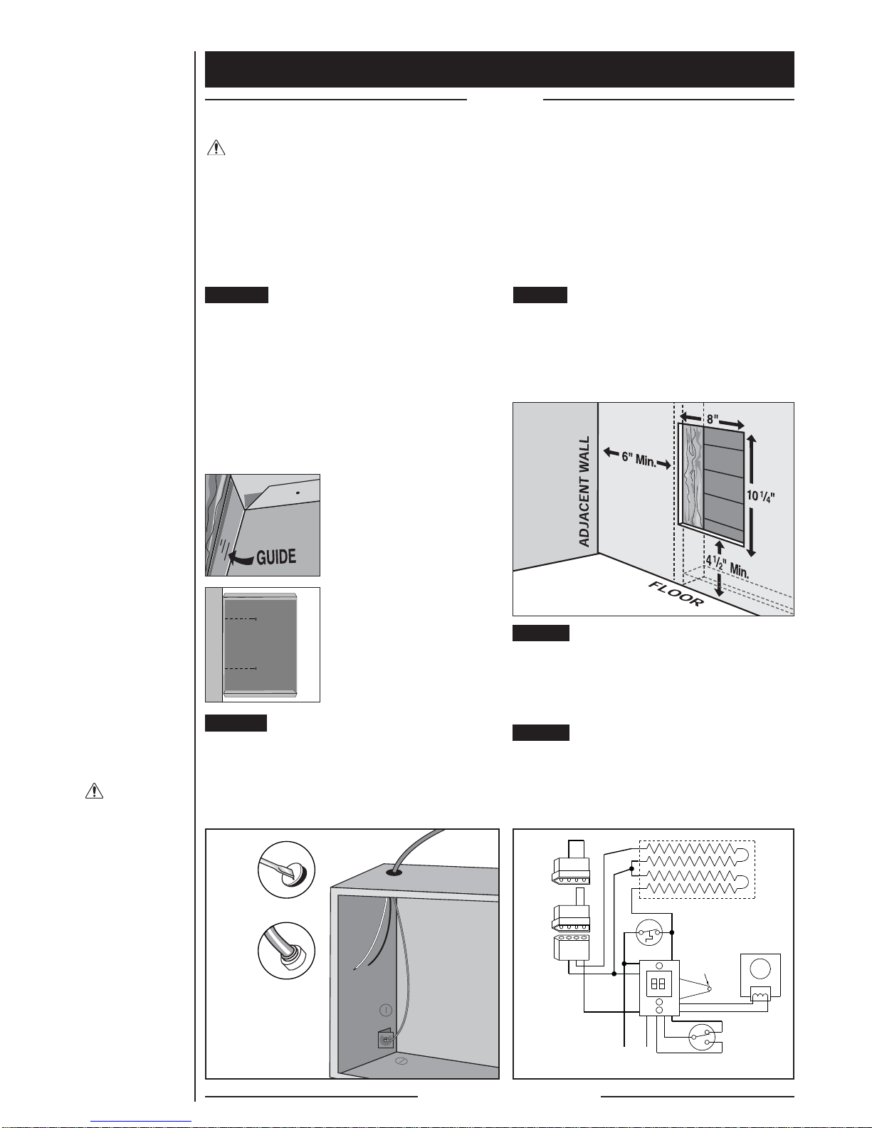
2. Remove furniture or other surfaces to appropriate clearances, so air can flow freely
throughout room. Maintain a minimum distance of 6 inches from adjacent surfaces,
4.5 inches from the floor, and 3 feet from furniture or other objects placed directly
in front of the heater.
3. See “Maximum Temperature Lock” on page 6.
1. The total amperage of all heaters on a branch circuit must not be more than
80% of the amperage rating of the circuit breaker and supply wire ratings.
Use a lower wattage heater, or reduce the number of heaters on the circuit.
2. Shorted supply or heater wires may be accompanied by severe sparking. Inspect all
supply and heater wiring insulation for damage. Do not reset the circuit breaker until
all electrical shorts have been repaired.
3. Replace the circuit breaker.
4. Replace heater assembly.
1. Turn rocker switch to HEAT mode.
2. Replace element.
1. If room temperature is being regulated and maintained, a low fan speed and low heat
output is normal for this energy saving heater.
2. Close doors and windows. Provide additional insulation, or install a higher wattage
heater or multiple heaters if necessary. (If your circuit is rated for more capacity.)
3. Replace heater assembly.
1. Clean heater (See “Maintaining Your Heater” section for instructions).
2.Turn off power at circuit breaker. Inspect all supply and heater wires for loose or poor
connections. Secure or reconnect all loose connections. Do not reset circuit breaker
until all connections have been checked or repaired.
1. Heater or fan motor requires replacement.
2. Remove obstruction and confirm that fan is spinning freely. Press reset button per the
“Maintaining Your Heater” section.
1. Adjust thermostat to a higher temperature until heater operates (See Problem #5 if the
problem persists).
2. Switch rocker switch to “HEAT” mode.
3. Press the manual reset button (See “Maintaining Your Heater” section for instructions).
4. Turn on the correct circuit breaker in the main panel.
5. Turn off power at circuit breaker. Check supply wire continuity and proper connection to
heater wires.
6. Repair or replace the heater assembly.
7. Correct the circuit breaker installation.
1. Clean heater (See “Maintaining Your Heater” section for instructions).
2. Remove obstruction. Maintain a minimum distance of 6 inches from adjacent surfaces,
4.5 inches from the floor, and 3 feet from furniture or other objects placed directly in
front of the heater.
3. Remove obstruction, and press heater manual reset button (See “Maintaining Your
Heater” section for instructions).
4. Replace heater assembly.
DIGITAL DISPLAY READS: PROBLEM SOLUTION
No Display
F1
F2
F3
F4
F6
F7
F8
12
24
1.No power, internal fuse blown, internal
control faulty
1.Grill is interfering with buttons
1.Wrong voltage selector key
1.Wrong voltage selector key
1.Line voltage is too low
2.Loose wire connections, or black/white key
is not fully engaged
1.Line voltage is too high
1. Thermal limit (temperature limiting control)
tripped
1.Internal control fault
1.No voltage selector key installed
1.No voltage selector key installed
1. Check that power is being supplied to heater; if operating on generator power,
make sure line frequency is correct; if display still doesn’t turn on then control
is defective and heater assembly must be replaced.
1. Turn power off at circuit breaker, realign grill so buttons can push freely.
Turn power back on at circuit breaker.
1. Turn power off at the circuit breaker, remove 120V white key, install 240V black
key, turn power back on at circuit breaker.
1. Turn power off at the circuit breaker, remove 240V black key, install 120V white
key, turn power back on at circuit breaker.
1. Clears automatically when line voltage returns to normal.
2. Check wire connections and that black or white key is securely in place.
1. Clears automatically when line voltage returns to normal.
1. Inspect heater for blockage, obstruction, and/or proper clearance. Move rocker
switch to center (NO HEAT) position and wait for heater to cool. Push manual reset
limit button per the MAINTAINING YOUR HEATER instructions (Page 8).
1. Disconnect power, reconnect power. If F8 code returns, control is faulty.
Replace heater assembly.
1.Turn power off at the circuit breaker, install 120V white key, turn power back on at
circuit breaker.
1.Turn power off at the circuit breaker, install 240V black key, turn power back on at
circuit breaker.
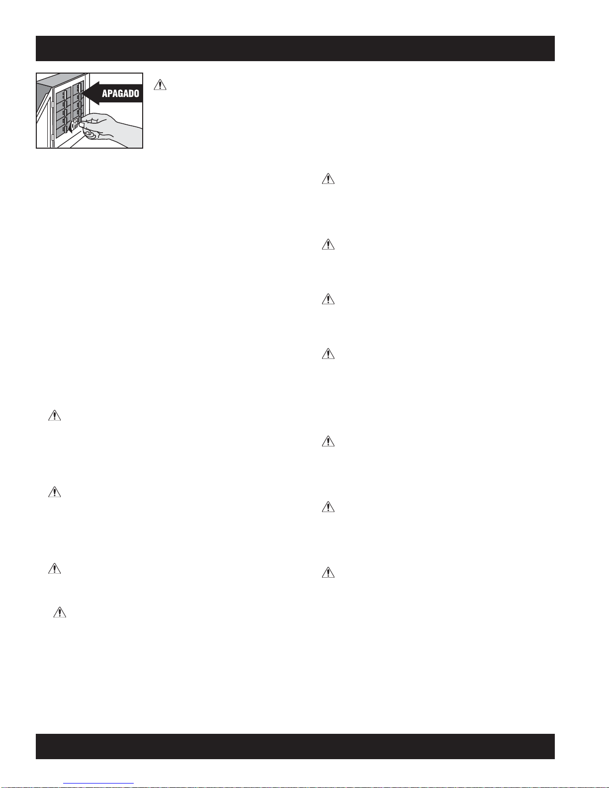
WARNING
Turn the electrical power off at the electrical panel board (circuit breaker or fuse box) and lock or tag the panel board
door to prevent someone from turning on power while you are working on the heater. Failure to do so could result in
serious electrical shock, burns, or possible death.
7