Enernet 13800 User manual

Pub No. 13801-022709
ENERNET Corporation Copyright 2009
Model 138 Programmable Serial Gateway
EnernetWorks™ Network Adapter

MODEL 13800 User Guide
ENERNET CORPORATION IS NOT RESPONSIBLE FOR ANY
RADIO OR TV INTERFERENCE CAUSED BY UNAUTHORIZED
MODIFICATIONS TO THIS EQUIPMENT. SUCH
MODIFICATIONS COULD VOID THE USER’S AUTHORITY TO
OPERATE THE EQUIPMENT.
THIS EQUIPMENT COMPLIES WITH PART 15 OF THE FCC
RULES. OPERATION IS SUBJECT TO THE FOLLOWING TWO
CONDITIONS: (1) THIS DEVICE MAY NOT CAUSE HARMFUL
INTERFERENCE, AND (2) THIS DEVICE MUST ACCEPT ANY
INTERFERENCE RECEIVED, INCLUDING INTERFERENCE
THAT MAY CAUSE UNDESIRED OPERATION.
ENERNET CORPORATION PROVIDES THIS PUBLICATION “AS
IS” WITHOUT WARRANTY OF ANY KIND, EITHER EXPRESS
OR IMPLIED, INCLUDING, BUT NOT LIMITED TO, THE IMPLIED
WARRANTIES OF MERCHANTABILITY OR FITNESS FOR A
PARTICULAR PURPOSE.
THIS MANUAL MAY CONTAIN TECHNICAL INACCURACIES
AND/OR TYPOGRAPHICAL ERRORS. CHANGES ARE
PERIODICALLY MADE TO THIS MANUAL, WHICH ARE
INCORPORATED IN LATER EDITIONS.
ENERNET CORPORATION MAY MAKE CHANGES AND
IMPROVEMENTS TO THE PRODUCT(S) AND/OR PROGRAMS
DESCRIBED IN THIS PUBLICATION AT ANY TIME WITHOUT
NOTICE.
IN NO EVENT WILL ENERNET CORPORATION BE LIABLE FOR
DAMAGES, INCLUDING LOST PROFITS, LOST SAVINGS OR
OTHER INCIDENTAL OR CONSEQUENTIAL DAMAGES
ARISING OUT OF THE USE OF OR INABILITY TO USE SUCH
PRODUCT, EVEN IF ENERNET CORPORATION OR AN
APPROVED RESELLER HAS BEEN ADVISED OF THE
POSSIBILITY OF SUCH DAMAGES, OR FOR ANY CLAIM BY
ANY OTHER PARTY.
ENERNET
Corporation
307 Dewittshire Road, Syracuse, New York 13214
Phone: (315) 449-0839 Fax: (315) 449-3056

MODEL 13800 User Guide
ANTENNA
The wireless RF equipment described in this document is supplied
with one of the following two (2) antenna configurations.
Helical element Monopole Antenna:
Antenna P/N ANT-916-CW-RH
Dipole Antenna with cable:
Antenna P/N ANT-916-MHW-RPS
Cable P/N PE36559-960
Warning:
This device has been designed to operate with the antennas listed
above and having a maximum gain of 2.15 dB. Antennas not
included in this list or having a gain greater than 2.15 dB are
strictly prohibited for use with this device. The required antenna
impedance is 50 ohms.
To reduce potential radio interference to other users, the antenna
type and its gain should be so chosen that the equivalent
isotropically radiated power (e.i.r.p.) is not more than that
permitted for successful communication.
FCC ID: TGD13800 / IC: 6120A-13800
This device complies with Part 15 of the FCC Rules. Operation is
subject to the following two conditions: (1) this device may not
cause harmful interference, and (2) this device must accept any
interference received, including interference that may cause
undesired operation.
Any changes or modifications not expressly approved by the party
responsible for compliance could void the user's authority to
operate the equipment.

MODEL 13800 User Guide
4
INTRODUCTION
This document discusses the model 138 Programmable Serial
Gateway — EnernetWorks™ Network Adapter (PSG). The
PSG Network Adapter provides a bridge between an
EnernetWorks™ 900MHz mesh network and an EIA-232
network interface device. EnernetWorks™ is a proprietary
mesh network protocol used to create connectivity among T9000
wireless thermostat Remote Control Nodes (RCN) and other
licensed devices manufactured by ENERNET Corporation. A
network interface device or other EIA-232-capable serial device
connects to the PSG Network Adapter. A single model 138
Programmable Serial Gateway Network Adapter can
accommodate data traffic from as many as 500
EnernetWorks™ capable nodes.
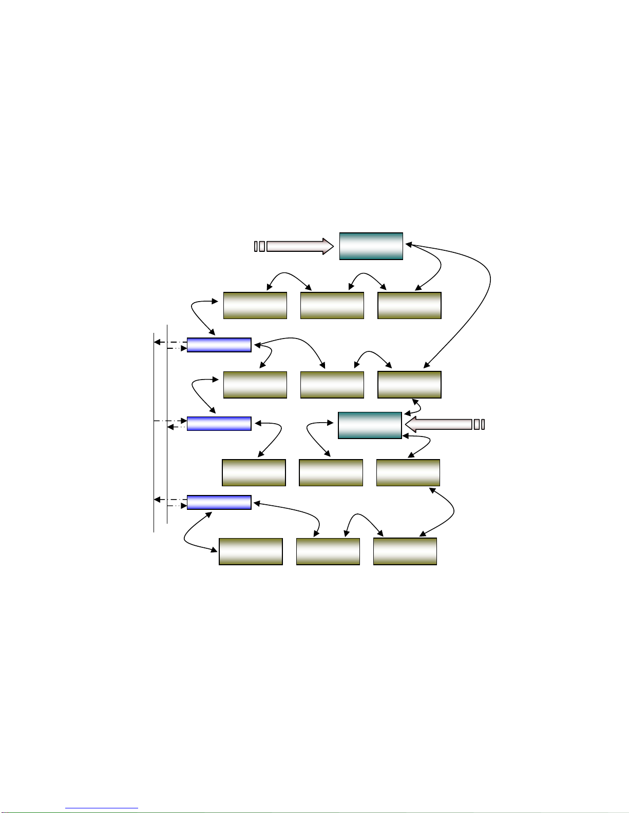
MESH NETWORK OVERVIEW
A simple overview example of EnernetWorks™ is shown in
Figure 1. A network interface device communicates with an
arbitrary number of targeted EnernetWorks™ capable nodes
via one or more PSG Network Adapters. Each node in the
network can be individually polled for status and other data, sent
operational commands or set to automatically report changes in
conditions and/or operating status. Communications can be
further extended by routing onto a power line carrier network using
the Model 125 wall-plug RF/PLC Bridge.
MODEL 13800 User Guide
5
Figure 1:
EnernetWorks™
Mesh Network Overview
Network
Interface Model 138
1st Gateway
Thermostat
Control Node Thermostat
Control Node Thermostat
Control Node
RF/PLC Repeater
RF/PLC Repeater
RF/PLC Repeater
Building Electrical wiring
Thermostat
Control Node Thermostat
Control Node Thermostat
Control Node
Thermostat
Control Node Thermostat
Control Node Thermostat
Control Node
Thermostat
Control Node Thermostat
Control Node Thermostat
Control Node
Model 138
2nd Gateway RS232
RS232
ØN
Network
Interface

MODEL 13800 User Guide
6
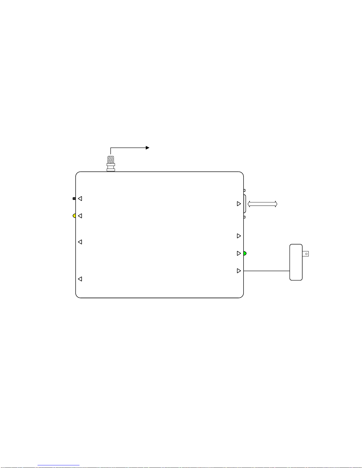
INTERCONNECTION
The PSG Network Adapter is powered by the supplied 9-volt DC
wall-plug power source. A standard 9-pin serial cable connects
the PSG Network Adapter to a network interface device. (Refer to
Figure 2.)
POSITIONING
Locate the PSG Network Adapter within RF mesh network range
of one or more EnernetWorks™ nodes to ensure sufficient
connectivity. Some installations may require the optional external
dipole antenna. (See RF COMMUNICATION TEST section
below.)
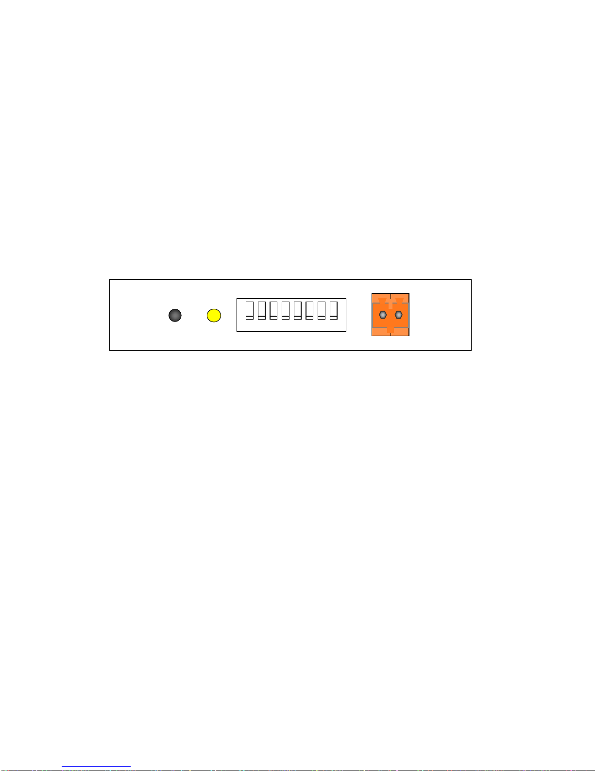
CONFIGURATION SWITCHES
Configuration switches set one of 256 possible network addresses
into the PSG Network Adapter in a binary fashion. See Figure 3
for Configuration Switch location and Table 1 for address setup. If
the selected network address is already in use, the Network
Adapter will light the Service LED indicating possible network
contention.
Decimal S1 S2 S3 S4 S5 S6 S7 S8
0 DN DN DN DN DN DN DN DN
1 DN DN DN DN DN DN DN UP
2 DN DN DN DN DN DN UP DN
3 DN DN DN DN DN DN UP UP
etc. DN DN DN DN DN UP DN DN
Table - 1
MULTIPLE PSG NETWORK ADAPTERS
If multiple PSG Network Adapters are needed because of a large
number of network nodes, or in the case of two or more
independent networks comingled within overlapping RF coverage,
configuration dip switches must be set to different domain
addresses. RCN’s and any other EnernetWorks™ capable
devices must also be set to the same network address. (See
specific device Operators Manual for details.)
MODEL 13800 User Guide
7
Figure 2: Network Adapter — Programmable Serial Gateway
ANT
CONNECTOR
Wall-Plug
9-Pin
Serial cable
A
NTENNA
P/N: ANT-916-CW-RH
NETWORK ADAPTER
SERVICE
CONFIGURATION
NETWORK
EIA-232
POWE
R
MODEL 13800 User Guide
8
Figure 3:
Network Adapter — Configuration Switches and Service Pin Button
NOTE:
The orange two-pin connector labeled “NETWORK” is not used.
12345678
SERVICE CONFIGURATION NETWORK
BUTTON LED

MODEL 13800 User Guide
9
TESTING
The PSG Network Adapter operates in two protocol modes –
binary and ASCII. Binary mode is used only by applications such
as the Monet™ suite, and enables detailed, automated control and
monitoring of target nodes on the mesh network. Refer to the
EnernetWorks™ Mesh Network API Guide for details.
ASCII mode is used primarily to test and configure the PSG
Network Adapter via the EIA-232 port. Perform the following
steps to configure the PSG Network Adapter:
1. Make sure PSG Network Adapter is unpowered
while making connections or changing
configuration switch settings.
2. Set building address per instructions on page 6,
Configuration Switches.
3. Set network interface device to 57600bps, 8 bits,
no parity 1 stop bit, flow control = NONE.
4. Connect 9-pin serial cable to the PSG Network
Adapter EIA-232 port and to your network interface
device.
5. Connect power cable to PSG Network Adapter. It
immediately sends the message,
“EnernetWorks™ Serial Gateway, Ver.
<firmware version #>”
6. You can now execute the following PSG Network
Adapter commands as needed:
CMD
?Display firmware version number
B or b Set building address. Same as setting DIP switches.
S or s Toggle serial diagnostic mode. Certain mesh network
responses are transmitted through the EIA-232 port in
ASCII format.
Displays Serial Diagnostic Mode= OFF/ON
R or r Reset PSG Network Adapter. Read the configuration
switch setting.
Displays Resetting
E or e Display last error:
ASCII Command Error
Frame Timeout Error
Frame Overrun Error
Busy
Binary Command Error
Unknown Room Number
Frame Format Error
No Error
No Neighbors

MODEL 13800 User Guide
10
N or n Invoke and display PSG Network Adapter neighbor
count (see next section)
X or x Enable/disable ASCII responses. Used to squelch any
ASCII asynchronous responses (i.e. send only binary
mode). This is reset by command R
Note: PSG Network Adapter transmits certain status
messages asynchronously, unless the X command has
been issued:
Line Break Detected
RF COMMUNICATION TEST
For proper operation, the PSG Network Adapter should be placed
within RF range of at least one other EnernetWorks™ node.
For maximum reliabilty it should link to at least four neighbors.
The following test requires connection to a network interface
device (see previous section, TESTING):
1. Make sure Configuration / Building address is set per
instructions on page 6, Configuration Switches.
2. If you are using the monopole helical antenna (standard
supplied configuration) place the PSG Network Adapter
in its proposed location. Then go to step 4.
3. If you are using the dipole/cable antenna option, place
only the antenna in its proposed location. Screw the
other end of the cable to the PSG Network Adapter
antenna connector. (WARNING: HAND TIGHTEN
ONLY, DO NOT USE TOOLS. Excessive force can
damage the connector!)
4. Issue the “N” command to send a neighbor count
command on the mesh network. PSG Network Adapter
responds with the message Neighbor Count = XX,
where XX is the actual number of EnernetWorks™
nodes heard.
5. If the Neighbor Count is less than 4, consider relocating
the PSG or antenna closer to other
EnernetWorks™ nodes.
Table of contents


