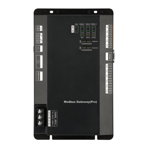
Gree ME30-24/E5 User manual

Modbus Gateway(Pro)

Safety Notices
Dear customer,
Please read this manual carefully prior to installation and operation and strictly observe all
installation and operation instructions covered in the manual.
Special attentions shall be paid to the following marks:
Please read this manual carefully before installation and operation and strictly observe the
installation and operation instructions covered in this manual.
WARNING.
This mark indicates operation, which if improperly performed, might lead to the death or
serious injury of the users.
CAUTION.
This mark indicates operation, which if improperly performed, might possibly result in damage
to the device.
WARNING
1. Installation shall be performed by the qualified personnel; otherwise it would result in a fire
hazard or electric shock.
2. Do not place the plug of the power supply into the socket before it is dried and cleaned.
3. Cut off the power supply before touching the electric element.
4. Do not touch this device with wet hands; otherwise it would result in electric shock.
5. Do use the power cable specified in this manual; otherwise it would result in a fire hazard.
6. When the power cable is reversely connected or the power supply is beyond the rated
range, it would result in a fire hazard or even damages to this device.
7. Do install this device inside the electric control cabinet which is located indoor and then is
locked.
8. Do install this device where it will not be subject to the electromagnetic interference or
heavy dust.
CAUTION
1. Be sure the specified adaptor is used; otherwise this device would work improperly or even
be damaged.
2. Be sure this device is setup in place; otherwise it would result in communication fault.
3. Be sure the communication line is connected to the correct interface; otherwise it would
result in communication fault.
4.After connection, lines should be protected with insulating tape to avoid oxidation and short
circuits.
5. Normal working conditions for Modbus Gateway(Pro):①Temperature: -20~+60℃,②
Humidity: less than 85%; ③Location: install this product in the electric control cabinet, not subject
to direct sunlight, rain and snow etc.
Contents
CHAPTER ⅠINSTALLATION.................................................................................................................... 1
1. SYSTEM INTRODUCTION................................................................................................................................. 1
2.COMPONENT INTRODUCTION .......................................................................................................................... 2
2.1 Component List...................................................................................................................................... 2
2.2 Gateway ME30-24/E5(M)..................................................................................................................... 2
2.3 Introduction of Photoelectric Isolation Converter.............................................................................. 5
2.4 Introduction of Photoelectric Isolation Repeater............................................................................... 6
3.DEVICE INSTALLATION..................................................................................................................................... 9
3.1 Product Dimension and Installation Space of Electric Control Cabinet......................................... 9
3.2 Communication Connection............................................................................................................... 10
CHAPTER ⅡDEBUGGING AND OPERATION..................................................................................... 14
1. HARDWARE DEBUGGING.............................................................................................................................. 14
1.1 DIP Switches........................................................................................................................................ 14
1.2 LED Display.......................................................................................................................................... 16
1.3 DI/DO .................................................................................................................................................... 17
2.COMMUNICATION DEBUGGING...................................................................................................................... 18
2.1 Communication Debugging with Air Conditioning Equipment EQUIPMENT.............................. 18
2.2 Communication Debugging with BMS System Equipment........................................................... 19
2.3 Malfunction Treatment........................................................................................................................ 20
CHAPTER ⅢMAINTENANCE................................................................................................................. 22
1.TROUBLESHOOTING OF BMS SYSTEM......................................................................................................... 22

Modbus Gateway(Pro) Technical Service Manual
1
Chapter ⅠInstallation
1.System Introduction
Gree Modbus Gateway(Pro) can achieve data exchange between air conditioner and BMS.
This gateway is applicable for Gree multi VRF which adopts CAN protocol. Modbus Gateway(Pro)
can collect, monitor and control operation data of multi VRF remotely and give out alarm when the
unit occurs error. Maintenance personnel doesn’t need to set each unit on site. They can check
the operation status, control startup and shutdown and set temperature of the air conditioning
system through computer, which greatly improves work efficiency and reduces human cost and
management cost.
BMS system
Other devices
Lighting
Fire control
Ventilation
Elevator
Electricity
Master
ODU
L1
Modbus
gateway 1
...
Slave ODU
...
IDU
...
L2
Master
ODU
ODU
Slave ODU
Slave ODU
IDU
IDU
IDU
IDUIDU
Modbus
gateway n
L3
L3
L3
L1
L1
CAN 1 bus
CAN 2 bus
CAN 2 network
CAN 1 network
Topology Introduction:
Modbus bus: L1 shown in the figure is the Modbus bus.
CAN1 network: which is consist of Modbus Gateway(Pro) and all IDUs and ODUs of the
system. One CAN1 network can be connected to maximum 80 IDUs.
CAN2 network: which is consist of Modbus Gateway(Pro) and main control ODU of the

Modbus Gateway(Pro) Technical Service Manual
2
system. One CAN2 network can be connected to maximum 16 systems and 255 IDUs.
System: One system consists of one set of outdoor unit (one set of outdoor unit is a module
group consisting of 1~4 modules, that is 1~4 outdoor units) and it’s connected indoor units.
Connectable unit quantity of Modbus Gateway(Pro): one Modbus Gateway(Pro) can be
connected with 16 outdoor units and 255 indoor units in maximum.
2.Component Introduction
2.1 Component List
2.1.1 Safety Requirements for Engineering Installation
Name
Model
Material
code
Supply
range
Remark
Modbus
Gateway(Pro)
Kits
Gateway
component
ME30-24/E5(M)
MC200016
80
Standard
equipped
Connectable to BMS system:
Protocol interface: Modbus RTU
protocol, CAN protocol
Hardware interface: RS485,
CAN
Baud rate: 9600,
Starting bit: 1,
Data bit: 8,
Parity bit: without,
Stopping bit: 1
Main components: Modbus
Gateway(Pro), User’s Manual.
Photoelectric
isolation
repeater
Photoelectric
isolation
repeater RS485
EN022000
10
Optional
A repeater shall be added for
every excessive 800m length of
communication wire. A repeater
shall be added for every
excessive 30 Modbus gateway.
The repeater is optional when
these conditions are met
Photoelectric
isolation
converter
Photoelectric
isolation
converter GD02
EN022000
20
Optional
The converter is optional when
BMS adopts RS232 way
Central control
cabinet
User prepared
\
User
prepared
\
2.2 Gateway ME30-24/E5(M)
2.2.1 General Functions
Gree Modbus Gateway(Pro) are intended to realize the data exchange between the air
conditioner and BMS, and provides ten I/Os (five inputs are DI1, DI2, DI3, DI4, DI5 and five
outputs are DO1, DO2, DO3, DO4, DO5). DI1 is the fire alarm interface (when there is fire alarm
signal input, Modbus gateway will order all air conditioners to stop operation immediately). The
status of other I/Os is mapped to the specific objects of the Modbus bus and is defined by the user.
This gateway is applicable for Gree multi VRF system which adopts CAN protocol.

Modbus Gateway(Pro) Technical Service Manual
3
2.2.2 Appearance
2.2.3 Composition
GMV gateway ME30-24/E5(M) contains the following parts:
Modbus Gateway(Pro)
1 set
User’s manual
1 piece
Specification
Gateway

Modbus Gateway(Pro) Technical Service Manual
4
2.2.4 Interface
1)Diagram of interface
RS485-1
communication
interface
CAN
communication
interface
RS485-2
communication
interface
Power input
DI Digital input
DO digital output
RS232
communication
interface
SD card interface
USB interface
Ethernet interface
2)Power Supply
Power supply should be 100VAC-240VAC, 50/60Hz.
Warning! Protective grounding of power input must be connected, otherwise a hazard
may happen; in addition, do not touch the power input when the gateway is energized.
Notice: Power cord should be secured with the equipped wire clip, as shown in the figure.
3)Communication Interfaces
CAN communication interface: It is connected to air conditioner through two-core

Modbus Gateway(Pro) Technical Service Manual
5
connection wire, to realize communication between Modbus Gateway(Pro) and air conditioner.
RS485-1 communication interface:It is connected to BMS through two-core connection wire,
to realize communication between Modbus Gateway(Pro) and BMS.
RS485-2 communication interface: This device doesn’t use this communication interface
currently.
Interface of USB or SD card: This device doesn’t use this interface currently.
Ethernet interface: This device doesn’t use this interface currently.
2.3 Introduction of Photoelectric Isolation Converter
2.3.1 Functions
Photoelectric isolation converter is used for converting RS232 signal and RS485 signal. It
shall be used only when user’s BMS system adopts RS232 communication way.
2.3.2 Appearance
Note: Please refer to the actual product; the picture is only for reference.
2.3.3 Instructions of Interfaces and Indicators
Power
RX
TX
C53
R+ R-
RS232
V+ V- E
DB9 female, connects
with computer serial port
Power wiring terminal
Power indicator
Indicator for receiving data
Indicator for sending data
RS485 wiring terminal

Modbus Gateway(Pro) Technical Service Manual
6
No.
Interface name
Usage instructions
Remark
1
Power interface
Input 12VDC800mA
Converter
equipped with
power supply
2
Communication
interface
Wire A of RS485 connects with R+ of 485
wiring terminal, wire B connects with R-.
RS232 interface connects with RS232 of
computer.
For more details,
please refer to the
user’s manual
3
Power indicator
It is always bright when power supply is put
through
For more details,
please refer to the
user’s manual
4
Communication
indicator
TX and RX lights are blinking when
communication is normal
For more details,
please refer to the
user’s manual
2.3.4 Product Dimension
2.3.5 Notices for Installation and Operation
Warning! It must be installed indoors, to avoid impact, direct sunlight or rain. It is suggested
to put it in the monitoring room with computer.
Warning! The devices provided by the manufacturer must be applied. Do not apply the
products of other models or brands.
Warning! Independent power supply shall be used. Sufficient 220V AC socket must be
installed to supply power.
2.4 Introduction of Photoelectric Isolation Repeater
2.4.1 Functions
Functions of photoelectric isolation repeater
1)When the distance of the whole communication network node exceeds 800m, it shall be
used to ensure the integrality of signal and avoid attenuation of signal in long communication
distance.
2)Currently, normal photoelectric isolation repeater can support the integrality of
communication signal of 32 nodes. When communication node quantity in the network exceeds 32
nodes, communication signal will not be integral. To ensure reliable transmission of signal,

Modbus Gateway(Pro) Technical Service Manual
7
photoelectric isolation repeater must be used to transmit signals when node quantity in the
network exceeds 30, so as to ensure the integrality of communication signal.
1 65432 7 8
0
1
Address
Address
1 1 0 1 0010 43
1234 5 6 7 8 value
DIP form
2.4.2 Appearance
Note: Please refer to the actual product; the picture is only for reference.
2.4.3 Instructions of Interfaces and Indicators
1 65432 7 8
0
1
Function
1
0
is the position of DIP
Without matched resistance
With matched resistance
7
7

Modbus Gateway(Pro) Technical Service Manual
8
No.
Interface name
Usage instructions
Remark
1
Power interface
Input 12VDC/800mA
Repeater
equipped with
power supply
2
Communication
interface
Wire A of RS485 connects with R+ of 485
wiring terminal, wire B connects with R-
For more details,
please refer to the
user’s manual
3
Power indicator
It is always bright when power supply is put
through
For more details,
please refer to the
user’s manual
4
Communication
indicator
Data light is blinking when communication is
normal
For more details,
please refer to the
user’s manual
2.4.4 Product Dimension
2.4.5 Notices for Installation and Operation
Warning! It must be installed indoors, to avoid impact, direct sunlight or rain. It is suggested
to put it in the monitoring room with computer.
Warning! The devices provided by the manufacturer must be applied. Do not apply the
products of other models or brands. Independent power supply shall be used. Sufficient 220V AC
socket must be installed to supply power.

Modbus Gateway(Pro) Technical Service Manual
9
3.Device Installation
3.1 Product Dimension and Installation Space of Electric Control
Cabinet
3.1.1 Product Dimension
1 65432 7 8
0
1
Function
1
0
is the position of DIP
Without matched resistance
With matched resistance
8
8
L ×W ×H:296×177×56(mm)
3.1.2 Installation Space of Electric Control Cabinet
Modbus Gateway(Pro) shall be installed in the electric control cabinet. The front side of
gateway shall be hung upwards and secured by four screws. Required installation space is shown
as below (only for reference).
CAUTION.
①It is suggested to install Modbus Gateway(Pro) near the air conditioner to reduce the
communication distance between Modbus Gateway(Pro) and air conditioner. As the
communication distance between Modbus Gateway(Pro) and air conditioner shall be within 500m
(please refer to 3.2 Communication Connection for more details). Communication distance
between Modbus Gateway(Pro) and BMS system can be expanded through 485 repeater.
②The power cord and communication cable of Modbus Gateway(Pro) shall be wired
separately. Otherwise, Modbus Gateway(Pro) may have errors! Fine dash line in the figure is the
communication cable and thick dash line in the figure is the heavy current wire. The wiring in the
figure is only for reference.
③Before making central control cabinet, please design according to the quantity and
Secure
it by four
screws
296mm
177mm With the front side
hung upwards
120mm 120mm 120mm
50mm
Wire groove
120mm 120mm
98.5mm
Electric control
cabinet
120mm
Wire groove

Modbus Gateway(Pro) Technical Service Manual
10
arrangement way of Modbus Gateway(Pro) and the placement status.
④Each Modbus Gateway(Pro) shall have independent power supply. Therefore, sufficient
220VAC socket for power supply must be installed in the central control cabinet.
⑤Keep the distance between communication cable and heavy current wire for more than
15cm and do not bind them together. If they cannot be kept away from 15cm, please apply
shielding steel pipe to avoid communication error caused by electromagnetic interference.
⑥The control cabinet shall be installed indoors to avoid direct sunlight and rain. It shall be
locked to keep it away from the reach of people other than management personnel.
3.2 Communication Connection
Communication system of Modbus Gateway(Pro) includes:
(1)Communication between Modbus Gateway(Pro) and BMS;
(2)Communication between Modbus Gateway(Pro) and air conditioner.
3.2.1 Material Selection of Communication Cable
Communication system
Material of cable
Com
munic
ation
cable
L(m)
Cable
diamete
r (mm2)
Material
standard
Remark
Modbus Ga
Communication between
Modbus Gateway(Pro)
and BMS
Light/Ordinary PVC
sheathed twisted pair
copper wire(60227
IEC52/60227 IEC53)
L≤80
0
≥2×0.75
IEC60227-5:
2007
When communication
distance exceeds
800m, photoelectric
isolation repeater shall
be added
Communication between
Modbus Gateway(Pro)
and air conditioner
Light/Ordinary PVC
sheathed twisted pair
copper wire(60227
IEC52/60227 IEC53)
L≤50
0
≥2×0.75
IEC60227-5:
2007
The length of
communication cable
shall not exceed 500m
3.2.2 Communication Connection Way
CAUTION! All communication cables of Modbus Gateway(Pro) must be connected in series
instead of in star mode.
(1)Communicaiton connection between Modbus and BMS;
BMS system
BMS system

Modbus Gateway(Pro) Technical Service Manual
11
(2)Communicaiton connection between Modbus Gateway(Pro) and air conditioner (n is air
conditioner quantity, n≤255);
ODU system 2
Module 1
(master ODU)
ODU system n
Module 1
(master ODU)
ODU system 1
Module 1
(master ODU)
……
……
……
ODU system 1
Module 1
(master ODU)
ODU system 1
Module 1
(master ODU)
ODU system 2
Module 1
(master ODU)
ODU system 2
Module 1
(master ODU)
ODU system n
Module 1
(master ODU)
ODU system n
Module 1
(master ODU)
ODU system 3
Module 1
(master ODU)
CAUTION! All communication cables of Modbus Gateway(Pro) must be connected in
series instead of in star mode.

Modbus Gateway(Pro) Technical Service Manual
12
1 2
①
②
BMS
ONON
1 2
SA8
ONON
…
…
④⑤
Modbus Gateway(Pro) 1
Master
ODU
Slave
ODU
Modbus Gateway(Pro) 2
Slave
ODU Master
ODU
SA8
③
④⑤
3.2.3 Communication Connection Steps
(1)Communication wire connection between Modbus Gateway(Pro) and BMS:
Step 1: Confirm the first Modbus Gateway(Pro) (Modbus Gateway(Pro)1 as shown in the figure)
that needs to be connected to BMS. Connect the R+ and R- port of RS485-1 communication
interface of this gateway and the BMS with communication cable, as shown in step ①in the
figure.
Step 2: Connect the R+ and R- port of RS485-1 communication interface of Modbus Gateway(Pr
o)(Modbus Gateway(Pro)1) and the R+ and R- port of RS485-1 communication interface of the se
cond Modbus Gateway(Pro)(Modbus Gateway(Pro)2 as shown in the figure) with communication
cable, as shown in step ②in the figure. If several Modbus Gateways(Pro) shall be connected,
please connect them in this way.
(2)Communication wire connection between Modbus Gateway(Pro) and air conditioner:
Step 1: Confirm the master ODU that each Modbus Gateway(Pro) shall be connected. Please
refer to “3.2.2(2) Communicaiton connection between Modbus Gateway(Pro) and air
conditioner”and adopt series connection, as shown in step ④in the figure.

Modbus Gateway(Pro) Technical Service Manual
13
Step 2: Connect the G1 and G2 port of CAN communication interface of Modbus Gateway(Pro)
and the G1 and G2 port of wiring board of corresponding master ODU with communication cable,
as shown in step ⑤in the figure.
(3)DIP switch of Modbus Gateway(Pro):
Step 1: Set address DIP switch of Modbus Gateway(Pro) by referring to chapter II.
Step 2: Set matched resistance of Modbus Gateway(Pro) by referring to chapter II.
Note:
①. In Modbus bus, if the connected Modbus Gateway(Pro) exceeds 30 or communication
distance exceeds 800m, one photoelectric isolation repeater shall be added. Connect the R+ and
R- port of photoelectric isolation repeater with the R+ and R- port of RS485-1 communication
interface of nearby Modbus Gateway(Pro).
30 Modbus gateways in maximum between two repeaters
Total accumulative length of communication cable
between two repeaters shall not exceed 800m
②. In “The eighth switch of function DIP switch –setting of CAN2 bus matched resistance”, the
setting method of matched resistance of Modbus Gateway(Pro) is introduced. Meanwhile, the
master ODU in the first and end systems of CAN2 bus shall be set as with matched resistance.
In the following, the detailed setting position and method of matched resistance of GMV 5 DC
inverter multi VRF are taken as example.
※CAN2 bus: Detailed meaning please refer to topology introduction.

Modbus Gateway(Pro) Technical Service Manual
14
Chapter ⅡDebugging and Operation
1. Hardware Debugging
1.1 DIP Switches
CAUTION! Please set DIP switches before using this device, otherwise this device cannot
operate normally!
This gateway includes two kinds of DIP switches, address DIP switch and function DIP switch.
1)Diagram of DIP Switches
HighLow
1 65432 7 8
0
1
is the position of DIP
This DIP is 0 This DIP is 1
2)Address DIP Switch –Address Setting of Modbus Gateway(Pro)
Address DIP switch is used for setting the device address of Modbus Gateway(Pro).
CAUTION! Please set the address DIP switches before using this gateway. The network
DIP switch address of the same bus cannot be repeated, otherwise communication error may
happen.
Address setting range: 1~255.
Address setting example:
Setting method of address 11 is shown as below:
1 65432 7 8
0
1
Address
Address
1 1 0 1 0000 11
1234 5 6 7 8 value
DIP form

Modbus Gateway(Pro) Technical Service Manual
15
Setting method of address 43 is shown as below:
1 65432 7 8
0
1
Address
Address
1 1 0 1 0010 43
1234 5 6 7 8 value
DIP form
3)The Seventh Switch of Function DIP Switch-Setting of Modbus Bus Matched Resistance
CAUTION! Master outdoor unit or gateway of the system which is at the end of Modbus
bus must be set as with the matched resistance, otherwise communication will be abnormal!
Modbus bus: Detailed meaning please refer to topology introduction.
The seventh switch of function DIP switch is used for setting the Modbus bus matched
resistance of this gateway.
If the gateway is at the end of Modbus bus, the gateway shall be set as with the matched
resistance, which means set the seventh DIP switch to 0;
If the gateway is not at the end of Modbus bus, the gateway shall be set as without the
matched resistance, which means set this DIP switch to 1.
DIP switch of matched resistance is shown as below:
1 65432 7 8
0
1
Function
1
0
is the position of DIP
Without matched resistance
With matched resistance
7
7
4)The Eighth Switch of Function DIP Switch –Setting of CAN2 Bus Matched Resistance
CAUTION! Master outdoor unit or gateway of the system which is at the end of CAN2 bus
must be set as with the matched resistance, otherwise communication will be abnormal!
※CAN2 bus: Detailed meaning please refer to topology introduction.
The eighth switch of function DIP switch is used for setting the CAN2 bus matched resistance
of this gateway.
If the gateway is at the end of CAN2 bus, the gateway shall be set as with the matched
resistance, which means set the eighth DIP switch to 0;
If the gateway is not at the end of CAN2 bus, the gateway shall be set as without the matched
resistance, which means set the eighth DIP switch to 1.
1 65432 7 8
0
1
Function
1
0
is the position of DIP
Without matched resistance
With matched resistance
8
8

Modbus Gateway(Pro) Technical Service Manual
16
1.2 LED Display
LED indicators shown in the above figure are divided into two parts: status indicators
(operation, alarm, power) and communication indicators(CAN, RS485, RS232). Operation status
of each indicator is shown in the following table.
CAN
RX
When the data from the equipment (e.g. air conditioner)
connected with Modbus Gateway(Pro) is received, it will
flash.
CAN
TX
When the data is transferred to the equipment (e.g. air
conditioner) connected with Modbus Gateway(Pro), it will
flash.
RS485-1
RX
When the data from the Modbus bus is received, it will
flash.
RS485-1
TX
When the data is transferred to the Modbus bus, it will
flash.
RS232
RX
This device does not use this LED indicator.
RS232
TX
This device does not use this LED indicator.
RS485-2
RX
This device does not use this LED indicator.
…
Master
control unit
of ODU
system 1
Set as with
matched
resistance
Set as
without
matched
resistance
Master
control unit
of ODU
system 2
Master
control unit
of ODU
system n
CAN2 bus
Set as
without
matched
resistance
Set as with
matched
resistance
…
Master
control unit
of ODU
system 1
Set as with
matched
resistance
Set as
without
matched
resistance
Master
control unit
of ODU
system 2
Master
control unit
of ODU
system n
CAN2 bus
Set as
without
matched
resistance
Set as with
matched
resistance

Modbus Gateway(Pro) Technical Service Manual
17
RS485-2
TX
This device does not use this LED indicator.
Power
When power supply of Modbus Gateway(Pro) is normal, it
will be always on..
Run
When Modbus Gateway(Pro) works normally, it will blink.
Alarm
This device doesn’t use this LED indicator.
1.3 DI/DO
This gateway supports 5 DIs(digital inputs) and 5 DOs(digital outputs); DO6 is reserved.
DI1...DI5
Digital inputs: 0/1 digital signals(binary system), applicable for those with power supply
DI1: in CAN2 network, fire alarm signal, connect “1”to the power of 12V, input fire alarm
signal “1”in DI 1 port, then Modbus gateway(Pro) will give out control, all units stop
operation immediately;disconnect “1”or connect to “0”, input signal “0”in DI 1
port,resume operation of all ODUs.
In CAN1 network, fire alarm signal, connect “1”to the power of 12V, input fire alarm
signal “1”in DI 1 port, then Modbus gateway(Pro) will give out control, all units stop
operation immediately;disconnect “1”or connect to “0”, input signal “0”in DI 1
port,resume operation of IDUs manually.
DI2...DI5: Defined by the user.
DO1...DO5 digital outputs: Relay output, normally-open contact
Max admissible power: 250VAC, 3A; 30VDC, 3A
Example: write “1”into DO5 of Modbus protocol and the two contacts of DO5 relay will be
closed; write “0”into DO5 of Modbus protocol and the two contacts of DO5 relay will
be cut off.
Other manuals for ME30-24/E5
1
Table of contents
Other Gree Gateway manuals

Gree
Gree TDmetal Modbus Gateway User manual

Gree
Gree ME30-24/E6 User manual

Gree
Gree ME30-44/D2 B User manual

Gree
Gree GRJW05-J User manual

Gree
Gree VRF User manual

Gree
Gree GMV BACnet Operating manual

Gree
Gree ME30-24/E6 User manual

Gree
Gree ME30-24/E5 User manual

Gree
Gree ME30-24/F1 K User manual

Gree
Gree MG30-24/D1(B) User manual