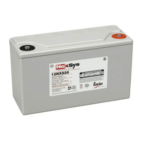
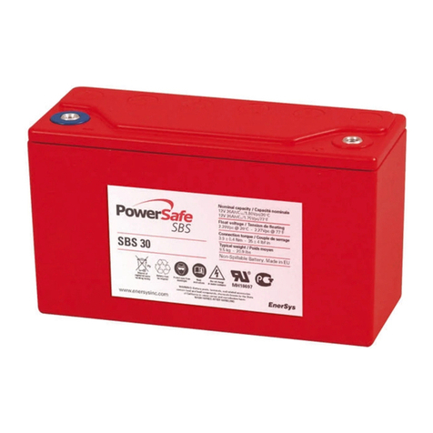
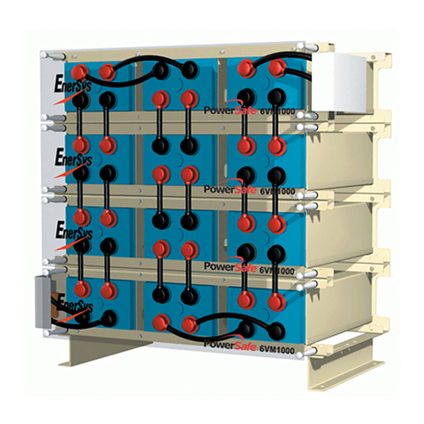
10 hr rate 8 hr rate Typical Short Circuit Internal
Battery Type(1) Nominal to 1.80Vpc to 1.75Vpc Length Depth(2) Height(3) Weight(4) Current(5) Resistance(5)
Voltage (V) @ 20°C @ 77°F mm mm mm kg (A) (mΩ)
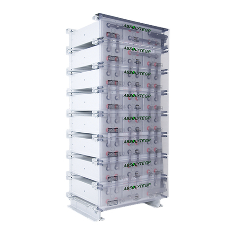
12VM-200 12 200 200 665 330 218 104 3045 0.694
12VM-300 12 300 300 893 330 218 149 4094 0.517
12VM-400 12 400 400 843 516 218 199 4604 0.456
12VM-500 12 500 500 957 516 218 232 5542 0.376
12VM-600 12 600 580 1071 516 218 265 5921 0.354
6VM-850 6 850 840 801 516 218 191 9521 0.222
6VM-1000 6 1000 1000 915 516 218 225 10772 0.195
6VM-1000A 6 1000 1000 801 584 218 230 9754 0.216
6VM-1100 6 1100 1080 972 516 218 245 11069 0.188
6VM-1200 6 1200 1200 915 584 218 267 12054 0.174
6VM-1300 6 1300 1300 972 584 218 291 12864 0.163
6VM-1360 6 1360 1360 1145 516 218 316 14092 0.149
6VM-1500 6 1500 1500 915 558 278 354 14822 0.142
6VM-1600 6 1600 1600 1145 584 218 363 16504 0.127
6VM-1700 6 1700 1640 972 558 278 382 16296 0.129
4VM-2000 4 2000 2000 791 558 278 308 20033 0.105
2VM-2600 2 2600 2600 676 584 218 188 25728 0.082
2VM-3000A 2 3000 3000 801 584 218 230 29262 0.072
2VM-3000 2 3000 3000 638 558 278 236 29644 0.071
2VM-3600 2 3600 3600 915 584 218 267 36162 0.058
2VM-4000 2 4000 4000 791 558 278 308 40066 0.053
2VM-4500 2 4500 4500 915 558 278 354 44466 0.047
2VM-5000 2 5000 4920 972 558 278 382 48888 0.043
Nominal Capacity (Ah)
Nominal Dimensions (mm)
The following items are recommended to be available to ensure a safe and
successful installation:
a) Safety glasses with side shields or safety goggles
b) Acid resistant gloves
c) Protective rubber aprons
d) Safety shoes
e) Insulated tools - torque wrench and socket set
f) Hammer drill - for floor anchor bolts
g) Tape measure
h) Chalk line
j) Line cord
k) Wooden or plastic straight edge
l) Spirit level - plastic
m) Cleaning materials - paper towels, wire wool , brass wire brush etc
n) Lifting device of suitable capacity for the module weight
p) A supply of clean water to rinse the eyes and/or skin in the event of any
contact with electrolyte
q) Spill containment and electrolyte neutralizing materials
(e.g. dilute Sodium Hydroxide)
If the safety precautions and installation procedures are not fully understood
clarification must be sought from your EnerSys®representative.
Notes:
(1) The excellent flexibility afforded by the modular construction design provides for further combinations of capacity, voltage or footprint in addition to those
illustrated in the above tabulation, eg 2VM-3200, 2VM-4800, 4VM-1000, 4VM-1700 etc.
(2) The depth shown in the table is for the module only. Add 86mm to obtain the overall depth including the front panel.
(3) To calculate the total height of a battery stack multiply the module height by the number of modules in the stack and add 100mm for the base support except
for the VM -1500, 1700, 2000, 3000, 4000, 4500 and 5000 modules where 120mm must be added.
(4) The typical weight of the module excludes the connectors, terminal plates, front panels and base support.
(5) Values refer to 2V cells.
3. Technical Specifications
4. Receiving and Inspection
Upon receipt of a delivery each case should be inspected for damage at the
time of unloading. Should any damage be identified it should be further
investigated then noted down and reported in writing to both the carrier and
your EnerSys®representative. Remove the lids from the packing cases and
check the cells and hardware against the packing/material list. Any missing
items should be notified immediately in writing to both the carrier and your
EnerSys representative. EnerSys is not responsible for damage or missing
items not reported as above. The terminal voltage of each cell should be
checked to ensure that none are below 2.12 volts. Any low voltage readings
should be reported to your EnerSys representative immediately.
5. Storage and Freshening Charge
Any cells/modules that are not to be installed immediately should be put into
storage in a cool, clean, dry, well ventilated area. Recommended storage
temperature range is -18°C (0°F) to 32°C (90°F).
Cells are supplied filled and charged from the factory. Lead-acid cells are
subject to self discharge. If cells are to be stored for several months, they will
require a freshening charge at six monthly intervals following receipt to keep
them in good condition. The initial “freshening charge-by date” is clearly
shown on the label attached to each packing case. The freshening charge
should be completed with the lids removed from the packing cases in an
adequately ventilated area. As with normal float charge operation, the
freshening charge should only be completed using a constant potential
charger. The correct float voltage can be obtained from Appendix “A” and
should be applied for 48 hours. A record should be kept of all freshening
charges applied during any prolonged storage period to maintain the
warranty.
If the cells are to be stored at high temperatures for prolonged periods you
should consult your EnerSys representative for further advice on freshening
charging.
6. Battery Location
The battery location should have an adequately strong level floor and be
clean, cool and dry with good lighting and ventilation. It is recommended that
a minimum free space of 900mm (36 inch) is provided in front of the battery to
allow for service and inspection. As a separate battery room is not required,
the best location for the battery is in the room with it’s associated power
supplies and equipment.
3


