Enforcement Technology Group ETG?IRHPK?050112 User manual

Copyright ©2012 Enforcement Technology Group, Inc. (ETGI). All rights reserved. Information Subject to Change Without Notice.
EnforcementTechnologyGroup,Inc.(ETGI)
400N.Broadway,4th Fl.
Milwaukee,WI53202
Phone:414‐276‐4471Fax:414‐276‐1533
Email:info@etgi.us Visit:www.etgi.us
VERSION:ETG‐IRHPK‐050112
INFRARED(IR)WIRELESSHEADPHONEKIT
OPERATINGMANUAL

Copyright ©2012 Enforcement Technology Group, Inc. (ETGI). All rights reserved. Information Subject to Change Without Notice.
COMPONENTLIST:
INTROUDUCTION/OVERVIEW:
•(4)Dual‐cupBatteryPowered,WirelessInfrared(IR)MonitoringHeadphones**
•(2)IRHeadphoneTransmitterBasesHardwiredto3.5mm(1/8”)“AudioSourceConnection” Cable
•(2)IRHeadphoneTransmitterBasePowerAdapters
•(2)3.5mm(male)toRCA(female)“Y” Adapters
•(2)3.5mm(female)to3.5mm(female)Couplers
•(2)12ft.RCACompositeAudioExtensionCables
•(2)3.5mm(female)to6.33mm(1/4”)(male)Adapters
**Requires(2)AAAAlkalineBatteries(notincluded).
TheIRHeadphoneTransmitterBaseisconnectedtoanExternalAudioSource.
TheTransmitterBaseturnsthesoundsproducedbytheExternalAudioSourceintoaseriesofpulses.Thepulses
worklikebitsinacomputer,digitallycapturingthesoundinformation.Thesepulsesarethensenttothe
TransmitterBase’sinfrared(IR)lightemittingdiode(LED).
TheLEDisadevicewhichproduceslightataparticularwavelength.TheinfraredLEDproduceslongwavelength
infraredlight.Itcannotbeseenwiththenakedeye,butworks muchlikevisiblelight.Itcanreflectoffofmirrors,
forexample,andcanbeblockedbyanyobjectsintheway.Becauseofthis,infraredheadphonescanonlybeused
whentheyarewithinalineofsightofthetransmitter.
TheIRMonitoringHeadphonesareequippedwithIRsensors(locatedontheear‐cups)thatpickupthelightwith
andturnitbackintosound.TheIRMonitoringHeadphoneshaveaninfraredcell,whichproducesapulseof
electricityeverytimeinfraredlightlandsonit.Thecellisdesignedtopickuptheparticularfrequencyoflight
producedbytheTransmitterBase,soitisnotdisturbedorthrownoffbyotherlight.Asmallcomputerinsideof
theheadphonestakesthesepulsesofelectricityandturnsthemintoanaudiosignal.Thisaudiosignalisthen
amplifiedwhichbecomeaudiblesound.
IRMONITORINGHEADPHONEBATTERY
INSTALLATION:
1. Removethebatterycompartmentcoverlocatedontherightear‐cupoftheIRMonitoringHeadphone.
NOTE: Aflatheadscrewdrivermaybeusedtohelpdetachthebatterycompartmentcoverfromthe
headphoneear‐cup.
2. Install(2)fresh/newAAAalkalinebatteriesintothebatterycompartmentaccordingtoproperpolarity(+/‐).
NOTE: Whenfresh/newAAAalkalinebatteriesareinstalled,thedevice canbepoweredon/usedfor
approximately25hours.
3. Replacethebatterycompartmentcover.

Copyright ©2012 Enforcement Technology Group, Inc. (ETGI). All rights reserved. Information Subject to Change Without Notice.
IRMONITORINGHEADPHONE
TRANSMITTERBASESET‐UP
ConnectingtheTransmitterBasetoanExternalPowerSupply:
1. Locatethe“PowerAdapter”providedwiththeIRMonitoringHeadphoneKit.
2. Insertthepinendofthe“PowerAdapter”intothe“DC12V”powerportlocatedontherearofthe
TransmitterBase.
3. Inserttheplugendofthe“PowerAdapter”intoanexternalpowersupplyoutlet.
ConnectingtheTransmitterBasetoanExternalAudioSource:
TheTransmitterBasecanbeconnectedtoANY ExternalAudioSourceequippedwithoneofthefollowing
commonaudiooutputjacks:3.5mm(1/8”),6.33mm(1/4”),orRCAcomposite.
TheconnectionbetweentheTransmitterBaseandExternalAudioSourceisfacilitatedviathe“AudioSource
Connection”cablethatishardwiredtotheTransmitterBase.
The“AudioSourceConnection”cablecanbeconnecteddirectlytoanExternalAudioSourceequippedwitha
3.5mm(1/8”)audiooutputjackorindirectlytoa6.33mm(1/4”)orRCAcompositeaudiooutputjacksviathe
providedadapters.
3.5mm(1/8”)ExternalAudioSourceConnection:
1. InserttheTransmitterBase’s“AudioSourceConnection”cabledirectlyintotheExternalAudioSource’s
3.5mm(1/8”)audiooutputjack.
NOTE: ThedistancebetweentheTransmitterBaseandExternalAudioSourcemaybeincreasedbyusingthe
“3.5mmCoupler”(provided)andlongerlengthof“3.5mmStereoCable”(notprovided).
6.33mm(1/4”)ExternalAudioSourceConnection:
1. InserttheTransmitterBase’s“AudioSourceConnection”cableintothefemaleendoftheprovided
“3.5mmto6.33mmAdapter.”
2. Insertthemaleendofthe“3.5mmto6.33mmAdapter”intotheExternalAudioSource’s6.33mm(1/4”)
audiooutputjack.
NOTE: ThedistancebetweentheTransmitterBaseandExternalAudioSourcemaybeincreasedbyusing
“3.5mmCoupler”(provided)andlongerlengthof“3.5mmStereoCable”(notprovided).
RCACompositeExternalAudioSourceConnection:
1. InserttheTransmitterBase’s“AudioSourceConnection”cableintoafemaleendofthe“3.5mm
Coupler”(provided).
2. Insertthe3.5mmmaleendoftheprovided“3.5mmtoRCAYCable”intotheotherendofthe“3.5mm
Coupler.”
3. InserttheRCAend(s)ofthe“3.5mmtoRCAYCable”intothemaleendsofthe"12ft.RCAComposite
AudioExtensionCable."
4. Inserttheothermalesendsofthe"12ft.RCACompositeAudioExtensionCable"intotheExternalAudio
Source’sRCAcompositeaudiooutputjack(s).
Copyright ©2012 Enforcement Technology Group, Inc. (ETGI). All rights reserved. Information Subject to Change Without Notice.
IRMONITORINGHEADPHONE
TRANSMITTERBASESET‐UP
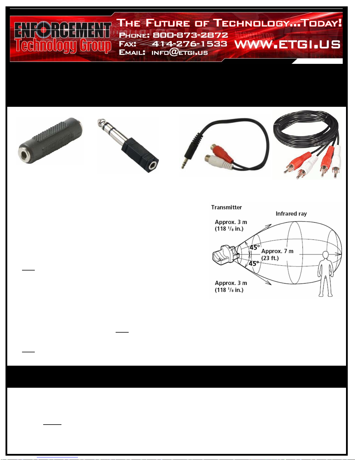
Forthebestaudioquality/performanceitisstronglyrecommend
thattheTransmittedBasestationissetonanelevatedsurfaceas
thiswillhelppreventtheIRbeingemittedbythecomponentfrom
beingblocked.
PleasenotethatmultipleTransmitterBasesmaybeusedtohelp
increasethecoverageareaoftheIRemission.
DoNOT placetheTransmitterBaseinanareathatisexposedto
directsunlightorstronglightasthismayinterruptthesound
transmission.
IfyouusetheIRMonitoringHeadphonesattoogreatadistance
fromtheTransmitterBase,youmayhearahissingnoiseandif
thereisanobjectbetweentheheadphonesandthetransmitter,
soundmaybeinterrupted.Thesephenomenaareinherentto
infraredraycommunicationanddoNOT meanthereisaproblem
withtheequipmentitself.
DoNOT covertheIRsensorslocatedontheearcups oftheIR
MonitoringHeadphonewithyourhandsorhair.
Infrared(IR)EmissionfromTransmitter
Illustration
3.5mm(1/8")Coupler
(female) 3.5mm(male)toRCA(female)
"Y"Adapter
3.5mm(female)to6.33mm(1/4")
(male)Adapter 12ft.RCAComposite
AudioExtensionCable
TransmitterBasePositioning:
OPERATIONS:
1. PowerOntheTransmitterBasebysettingthecomponent’s“POWER” switch(locatedonrear)tothe“ON”
position.
2. PowerOntheIRHeadphonebypressingthedevices“ON/OFF” button(locatedonbottomofrightear‐
cup).NOTE: Thecomponent’sredLEDwillturnonsignalingthatthedeviceison/receiving power.
3. AdjusttheIRHeadphone’s“VolumeControl”dial(locatedonbottomofleftear‐cup)untildesiredlistening
volumelevelisachieved.
Table of contents


