Engel HFI22 Series User manual


Integrated Synchronous Servo Drives
HFI 22xx / HFI 26xx / HFI 32xx / HFI 37xx
Document History
Operating Manual Rev. 1.3 www.engelantriebe.de Page 1
Document History
Document
Date
(dd.mm.yyyy)
Rev
Changes
HFI_BA_Rev1.0_180627_de
27.06.2018
1.0
First revision of HFI_BA
HFI_BA_Rev1.1_180912_en
12.09.2018
1.1
Update of the reference standards in chapters 4 and 6
HFI_BA_Rev1.2_190628_en
28.06.2019
1.2
Update of System Data
HFI_BA_Rev1.3_201125_en
25.11.2020
1.3
-Addition of internal wiring of DOs in installation plan
(10.2)
-Complementation of Requirements of the STO line
(10.1.3)
-Complementation of chapter Digital inputs/limit
switches (8.3)
-Revision of chapter I²t monitoring (8.5)
Copyright
The information and specifications in this document have been compiled with great care and to the best of our
knowledge. However, specifications differing between the document and the product cannot be eliminated with absolute
certainty. ENGEL assumes no liability whatsoever for errors or consequential damages resulting from these deviations.
No liability is assumed for damages which arise from the use of the device with the use of applications or defective cir-
cuits, either. ENGEL reserves the right to change, supplement or improve the document or the product without prior
notice. This document may not, without the express authorization of the copyright holder, be reproduced in any way or
be transmitted in another natural or machine language or on data carrier, whether this would take place electronically,
mechanically, visually or in any other manner.

Integrated Synchronous Servo Drives
HFI 22xx / HFI 26xx / HFI 32xx / HFI 37xx
Table of Contents
Operating Manual Rev. 1.3 www.engelantriebe.de Page 2
Table of Contents
DOCUMENT HISTORY.........................................................................................................................................1
TABLE OF CONTENTS..........................................................................................................................................2
1 INTRODUCTION ..............................................................................................................................................4
2 SYMBOLS USED IN THIS DOCUMENT .............................................................................................................4
3 ABBREVIATIONS USED IN THIS DOCUMENT .................................................................................................4
4 SAFETY INFORMATION AND INSTRUCTIONS FOR USE .................................................................................5
4.1 Definition of the direction of rotation for motors............................................................................................. 5
5 FUNCTIONAL DESCRIPTION ...........................................................................................................................6
5.1 Type key ....................................................................................................................................................7
6 TECHNICAL DATA ............................................................................................................................................8
6.1 System Data ............................................................................................................................................... 8
6.2 System Data HFI22xx ..................................................................................................................................9
6.2.1 HFI2230 characteristics ................................................................................................................... 10
6.2.2 HFI2260 characteristics ................................................................................................................... 10
6.3 System Data HFI26xx ................................................................................................................................ 11
6.3.1 HFI2630 characteristics ................................................................................................................... 12
6.3.2 HFI2660 characteristics ................................................................................................................... 12
6.4 System Data HFI32xx ................................................................................................................................ 13
6.4.1 HFI3260 characteristics ................................................................................................................... 14
6.4.2 HFI3290 characteristics ................................................................................................................... 14
6.5 System Data HFI37xx ................................................................................................................................ 15
6.5.1 HFI3760 characteristics ................................................................................................................... 16
6.5.2 HFI3790 characteristics ................................................................................................................... 16
6.6 Important technical Information ................................................................................................................. 17
6.6.1 Regenerative operation ................................................................................................................... 17
6.6.2 Lead fuses ..................................................................................................................................... 17
6.6.3 Service life expectancy .................................................................................................................... 17
6.6.4 Safety installations .......................................................................................................................... 18
7 DSERV SERVICE SOFTWARE ........................................................................................................................ 19
7.1 System requirements................................................................................................................................. 19
7.2 Installation and start-up of the program ...................................................................................................... 19
7.2.1 Installation of the software .............................................................................................................. 19
7.2.2 Program start ................................................................................................................................. 20
7.2.2.1 Error messages after program start ..................................................................................... 20
7.2.2.2 Starting multiple instances of DSerV .................................................................................... 21
7.3 Using the DSerV service software ............................................................................................................... 22
7.3.1 File menu....................................................................................................................................... 23
7.3.2 Optimisation menu.......................................................................................................................... 25
7.3.3 Monitor menu................................................................................................................................. 26
7.3.4 Diagnostic menu ............................................................................................................................. 28
7.3.5 Options menu................................................................................................................................. 29
7.3.6 ? menu .......................................................................................................................................... 29
7.3.7 Note on language selection.............................................................................................................. 29
8 PARAMETERISATION ................................................................................................................................... 30
8.1 Control interface selection .......................................................................................................................... 30
8.2 Operating mode selection........................................................................................................................... 31
8.2.1 Current control/torque control mode................................................................................................. 32
8.2.1.1 Current control with/without speed limitation ....................................................................... 32
8.2.1.2 Current setpoint................................................................................................................. 34
8.2.1.3 Speed limit source ............................................................................................................. 35
8.2.1.4 Parameters of the current control loop................................................................................. 36

Integrated Synchronous Servo Drives
HFI 22xx / HFI 26xx / HFI 32xx / HFI 37xx
Table of Contents
Operating Manual Rev. 1.3 www.engelantriebe.de Page 3
8.2.2 Speed control mode ........................................................................................................................ 38
8.2.2.1 Speed control with/without torque limitation ........................................................................ 38
8.2.2.2 Speed setpoint .................................................................................................................. 40
8.2.2.3 Torque limit source ............................................................................................................ 41
8.2.2.4 Parameters of the speed control loop .................................................................................. 42
8.2.3 Positioning mode ............................................................................................................................ 47
8.2.3.1 Homing............................................................................................................................. 48
8.2.3.2 General positioning parameters........................................................................................... 54
8.2.3.3 Target positions................................................................................................................. 61
8.3 Digital inputs/limit switches ........................................................................................................................ 66
8.4 Digital outputs .......................................................................................................................................... 69
8.5 I²t monitoring ........................................................................................................................................... 71
9 CONNECTION ASSIGNMENT ........................................................................................................................ 72
9.1 X1 –Supply and signals ............................................................................................................................. 72
9.2 X2 –CAN signal plug ................................................................................................................................. 73
9.3 X3 –STO signal plug ................................................................................................................................. 74
9.4 X4, X5 –Fieldbus modules ......................................................................................................................... 74
10 INSTALLATION ........................................................................................................................................... 75
10.1 Cable type, cable length and shielding ....................................................................................................... 75
10.1.1 Requirements on the supply/signal line (connection to X1)................................................................ 75
10.1.2 Requirements on the CAN line (connection to X2) ............................................................................ 75
10.1.3 Requirements on the STO line (connection to X3) ............................................................................ 77
10.1.4 Requirements on the fieldbus lines (connection to X4 and X5)........................................................... 77
10.2 Installation diagram ................................................................................................................................. 78
11 COMMISSIONING....................................................................................................................................... 79
12 STATUS DISPLAY, ERROR MESSAGES ....................................................................................................... 80
12.1 Status display.......................................................................................................................................... 81
12.1.1 HFI without communication module................................................................................................ 81
12.1.2 HFI with communication module .................................................................................................... 81
12.1.2.1 EtherNet/IP ..................................................................................................................... 82
12.1.2.2 EtherCAT......................................................................................................................... 82
12.1.2.3 PROFINET ....................................................................................................................... 83
12.2 General error messages ........................................................................................................................... 84
12.3 Error messages in positioning mode .......................................................................................................... 85
12.4 CAN status display ................................................................................................................................... 86
12.5 CAN error messages ................................................................................................................................ 86
13 CONTROLLER OPTIMISATION ................................................................................................................... 87
13.1 Current controller .................................................................................................................................... 87
13.2 Angle sensor offset determination, motor pole number ............................................................................... 87
13.3 Speed controller adjustment ..................................................................................................................... 88
14 MECHANICAL DIMENSIONS....................................................................................................................... 89
14.1 HFI 2230 / HFI 2260................................................................................................................................ 89
14.2 HFI 2630 / HFI 2660................................................................................................................................ 89
14.3 HFI 3260 / HFI 3290................................................................................................................................ 90
14.4 HFI 3760 / HFI 3790................................................................................................................................ 90
14.5 Mounting instructions for planetary gear GPK ............................................................................................. 91
HFI_BA_Rev1.3_201125_en
Technical changes reserved

Integrated Synchronous Servo Drives
HFI 22xx / HFI 26xx / HFI 32xx / HFI 37xx
Introduction
Operating Manual Rev. 1.3 www.engelantriebe.de Page 4
1Introduction
This document describes the technical data and functions of the HFI series of integrated synchronous servo drives. It
explains the functional capabilities of the drives, serves for the drive project design and explains the correct procedure
for installation and commissioning of the devices.
The drives of the HFI series are optionally equipped with different communication modules. The specific communication
protocols are described in the corresponding documents (CANopen® Manual, EtherCAT® Manual …).
2Symbols used in this document
Symbol
Signal
Word
Meaning
Attention!
This symbol refers to safety and warning notices. Non-observance can result in personal injury
and/or damage to property.
Note!
This symbol refers to useful hints, which should help to avoid or find errors.
3Abbreviations used in this document
Abbreviation
Meaning
AI
Analogue Input
CAN
Controller Area Network
CANopen
communication protocol for CAN-Bus systems
CiA
CAN in Automation - CAN users’ and manufacturers’ organization
DO
Digital Output
DI
Digital Input
DSP 402
CANopen device profile for drives and motion control
I/F
Interface
Node-ID
CAN Node Identifier
PMSM
Permanent Magnet Synchronous Motor
RPM
Revolutions per Minute
Integrated Synchronous Servo Drives
HFI 22xx / HFI 26xx / HFI 32xx / HFI 37xx
Safety information and instructions for use - Definition of the direction
of rotation for motors
Operating Manual Rev. 1.3 www.engelantriebe.de Page 5
4Safety information and instructions for use
Attention!
The safety instructions must be observed!
Non-observance of the safety instructions can result in personal injury and damage to prop-
erty.
During the installation, commissioning and maintenance, the applicable safety and
accident prevention regulations must be observed for the specific application.
The device applies as electronic equipment and is intended for operation in machines.
The safety instructions of the Machinery Directive (2006/42/EC) must be observed.
Prior to commissioning, it must be ensured that the drive does not pose any hazards
and that no uncontrolled movements can occur.
Do not plug or unplug connectors while energized!
The following regulations apply with no claim to completeness:
VDE 0100 Low-voltage electrical installations
EN 60204-1 Safety of machinery –Electrical equipment of machines
EN 61800 Adjustable speed electrical power drive systems
Attention!
Functional Safety
For devices with functional safety (HFIxxxx-Sx00-xx)the operating instructions supplement
Integrated Drives HFI equipped with STO-Module
must also be consulted.
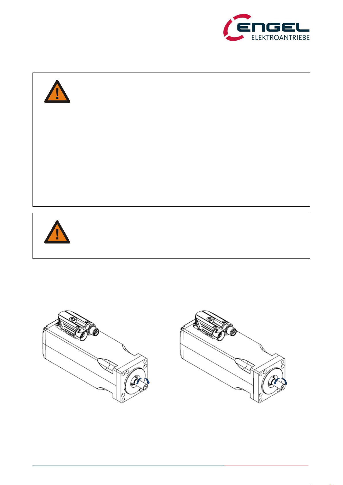
4.1 Definition of the direction of rotation for motors
In accordance with DIN EN 60034-8 the direction of rotation is the direction viewed from the drive end. I.e. with clock-
wise rotation the shaft turns clockwise and with counter-clockwise rotation the shaft turns counter-clockwise (viewing
direction onto the shaft end).
Figure 4-1: Direction of rotation for motors
clockwise rotation (cw)
counter-clockwise rotation (ccw)

Integrated Synchronous Servo Drives
HFI 22xx / HFI 26xx / HFI 32xx / HFI 37xx
Functional description
Operating Manual Rev. 1.3 www.engelantriebe.de Page 6
5Functional description
In the HFI series of integrated drives, powerful and dynamic synchronous servo motor systems (PMSM) designed in
concentrated winding technology are combined with compact electronics to form high-quality drive systems. The devices
are designed for operation at low voltage, their cascaded current, speed and position control loops provide a dynamic
operation. The integrated positioning control offers a temporally optimised point-to-point positioning with trapezoidal or
jerk-limited speed progression.
Operation of the device is possible either via fieldbus or via digital and analogue inputs and outputs. The flexibility of the
devices is provided through communication modules. The following variants are currently supported:
EtherCAT-communication module (Anybus CompactCom™40-series)
PROFINET-communication module (Anybus CompactCom™40-series)
EtherNet/IP-communication module (Anybus CompactCom™40-series)
Furthermore, the device is available in a CAN-variant. In this variant no communication module is required. Communica-
tion takes place via CANopen according to CiA DSP 402 V2.0.
The simple parameterisation/configuration of the device takes place with the parameterisation software DSerV (WIN-
DOWS, COM-Port).
Overview of features:
dynamic compact drives for decentralised use; no space in the control cabinet required
powerful designs with up to 1.8 Nm rated torque and 4.0 Nm peak torque
designs for operation at 24 VDC or 48 VDC
separated logic supply providing runtime data retention during power down conditions
short cycle times of the PI current (100 µs), PI speed (100 µs) and P position (200 µs) controllers with a powerful
signal processor
point to point positioning functionality with linear or Sin² speed ramp
12-bit high-resolution angle sensor system
variable fieldbus interface via communication module (optional)
CAN-interface (optional), galvanically isolated. CANopenwith implementation of device specification CiADSP 402
V2.0.
available with permanent magnet parking brake
available with planetary gear
high protection class IP54 (higher protection class on request)
parameterisation/configuration with the parameterisation software DSerV (WINDOWS, COM-Port)

Integrated Synchronous Servo Drives
HFI 22xx / HFI 26xx / HFI 32xx / HFI 37xx
Functional description - Type key
Operating Manual Rev. 1.3 www.engelantriebe.de Page 7
5.1 Type key
HFI
2660
N
2
00
-
options
Options:
see list of options below
Version:
00: standard type
xx: customer specific
Supply voltage:
2: 24 VDC; 4: 48 VDC
Safety:
N: non-safety
S: Safety
Drive size:
2230, 2260, 2630, 2660
3260, 3290, 3760, 3790
Series:
HFI
List of options (non-exhaustive)
HB
parking brake
permanent magnetic, installed in the motor
CO
CANopen Interface
additional M12 connector
EC
EtherCAT
fieldbus communication module
EI
EtherNet/IP
fieldbus communication module
PN
PROFINET
fieldbus communication module
SC
surface coating
housing
GPK-xxx
planetary gear GPK
mounted onto the motor, gear reduction xxx : 1
Attention!
Functional Safety
For devices with functional safety (HFIxxxx-Sx00-xx)the operating instructions supplement
Integrated Drives HFI equipped with STO-Module
must also be consulted.

Integrated Synchronous Servo Drives
HFI 22xx / HFI 26xx / HFI 32xx / HFI 37xx
Technical Data - System Data
Operating Manual Rev. 1.3 www.engelantriebe.de Page 8
6Technical Data
6.1 System Data
Designation
Unit
Value
additional information
Input Voltage*1)
VDC
24 / 48
20 %
Ambient Temperature
°C
0 ... 40
No condensation permissible
Storage Temperature
°C
-25 ... 60
No condensation permissible
Number of poles
6
Protection Class
IP54
(higher protection class on re-
quest)
Analogue Inputs
AI1 (differential input)
10 V, 12 bit, Ri=22 k
can optionally be used as digital
input (DI6)
Digital Inputs
DI1 ... DI8
V
0.0 Uoff 5.0
15.0 Uon 30
DI1 = control enable
DI4/DI5 can optionally be used
as digital output DO2/DO1
Digital Outputs
DO1, DO2
24 V, 50 mA
open collector, ground switch-
ing*3), 33 series resistance,
without pull-up resistor,
can optionally be used as inputs
Serial Interfaces
RS232
Communication with DSerV
parameterisation software
CAN 2.0B (max. 1 MBit/s)
galvanically isolated
without termination resistor
Electromagnetic compati-
bility
Emission *2)
DIN EN 61800-3: 2012-09
second environment/limited
availability (Cat. C3)
Immunity
DIN EN 61800-3: 2012-09
second environment
*1) Observe chapter 6.6.1 Regenerative operation
*2) Cable-conducted emissions must be suppressed through appropriate filtering measures in the energy supply (e.g.
power supply unit) of the device
.
*3) Internal wiring of DOs see chapter 10.2 Installation diagram.

Integrated Synchronous Servo Drives
HFI 22xx / HFI 26xx / HFI 32xx / HFI 37xx
Technical Data - System Data HFI22xx
Operating Manual Rev. 1.3 www.engelantriebe.de Page 9
6.2 System Data HFI22xx
Designation
Unit
Value
additional information
HFI2230
HFI2260
Rated speed
min-1
4000
3000
Peak speed
min-1
5000
4000
Rated input current*1)
ADC
6.1 / 3.0
7.1 / 3.6
24V-Type/48V-Type
Rated motor current*2)
Aspk
9.5 / 4.8
12.3 / 6.2
24V-Type/48V-Type
Peak motor current*2)
Aspk
19.5 / 9.8
25.0 / 12.5
24V-Type/48V-Type
Motor current measurement
range
A
27.5 / 13.8
55.0 / 27.5
24V-Type/48V-Type
Rated power*3)
W
95
120
Rated torque*3)
Nm
0.23
0.38
Peak torque
Nm
0.50
0.8
Torque constant
Nm/A
0.027 / 0.054
0.033 / 0.066
24V-Type/48V-Type
Voltage constant
V/1kmin-1
3.3 / 6.6
4.0 / 8.0
24V-Type/48V-Type
Flange dimension
mm²
47 x 47
Drive length (without fieldbus
module)*4)
mm
129 / 161
159 / 191
without/with parking brake
Weight
kg
0.85 / 1.0
1.15 / 1.3
without/with parking brake
Parking Brake (optional):
automatically operated
Static braking torque
Nm
1.0
Power (electric)
W
10
*1) The rated input current is the direct current drawn in nominal operation (rated torque at rated speed) from the input
voltage (24 VDC or 48 VDC). The current drawn from the input voltage is proportional to the converted power, not
to be confused with the torque-building motor current, which is displayed as sine peak value in DSerV and is pro-
portional to the motor torque.
Please also observe that the supply line is lossy. This leads to a reduction in voltage and speed at the motor system
and to increased power consumption of the device. A connection line with a nominal cross-section of 1.5 mm² al-
ready has an overall loss resistance of approx. 2 x 12.5 mΩ/m (conductors and return conductors)! Appropriate pow-
er reserves must be provided in the supply!
*2) Motor phase current as a sine peak value, which is required for the generation of the rated or peak torque. Motor
phase current is displayed in DSerV. Not to be confused with the current taken from the supply.
*3) The specified values apply for the installation of the drive on a system surface made of aluminium (A = 0.1 m²,
d = 10 mm). It must be taken into consideration that the specified continuous output power must be derated for
thermally unfavourable couplings.
*4) With fieldbus module the length of the drive increases by 14 mm.
Integrated Synchronous Servo Drives
HFI 22xx / HFI 26xx / HFI 32xx / HFI 37xx
System Data HFI22xx - HFI2230 characteristics
Operating Manual Rev. 1.3 www.engelantriebe.de Page 10
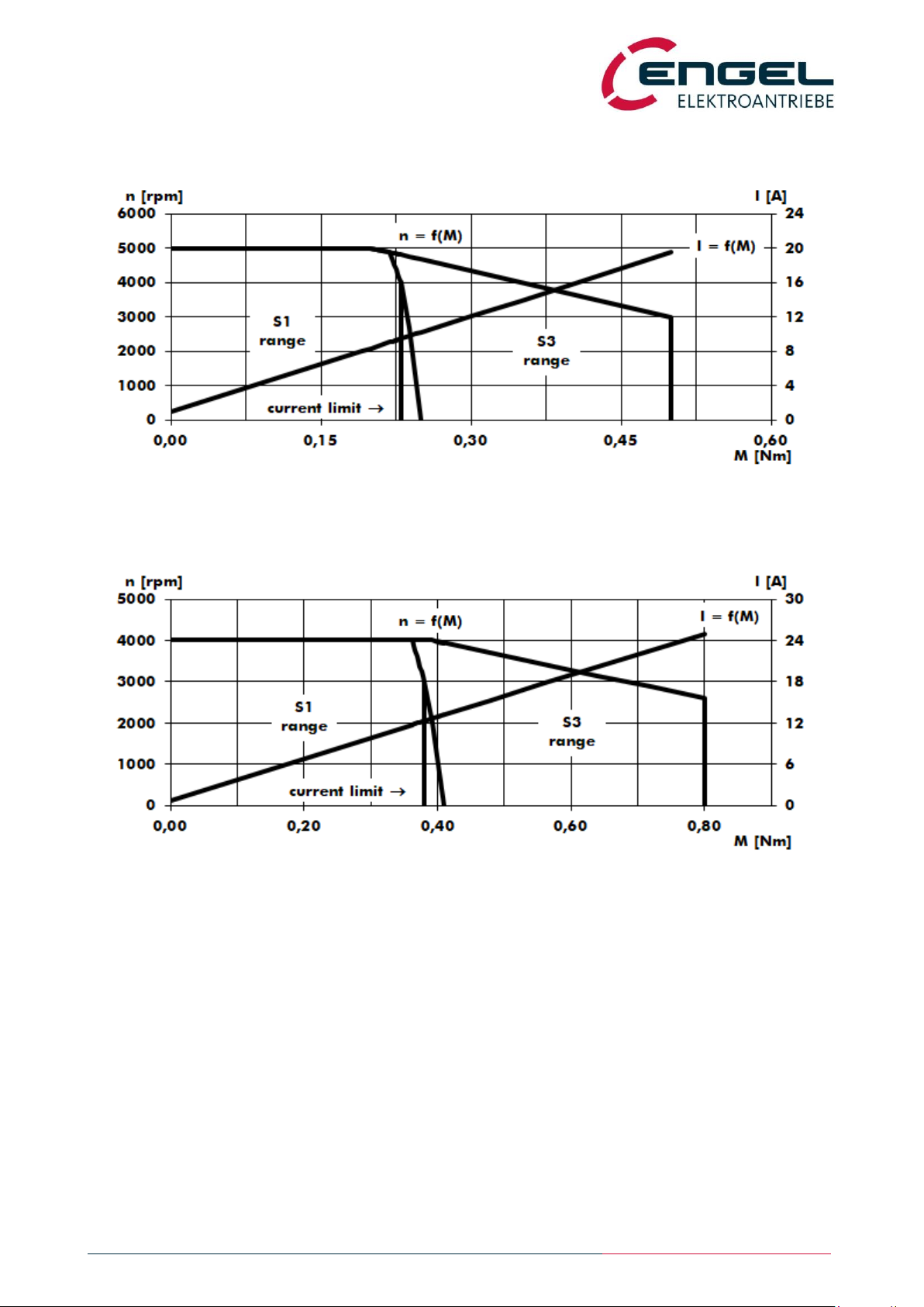
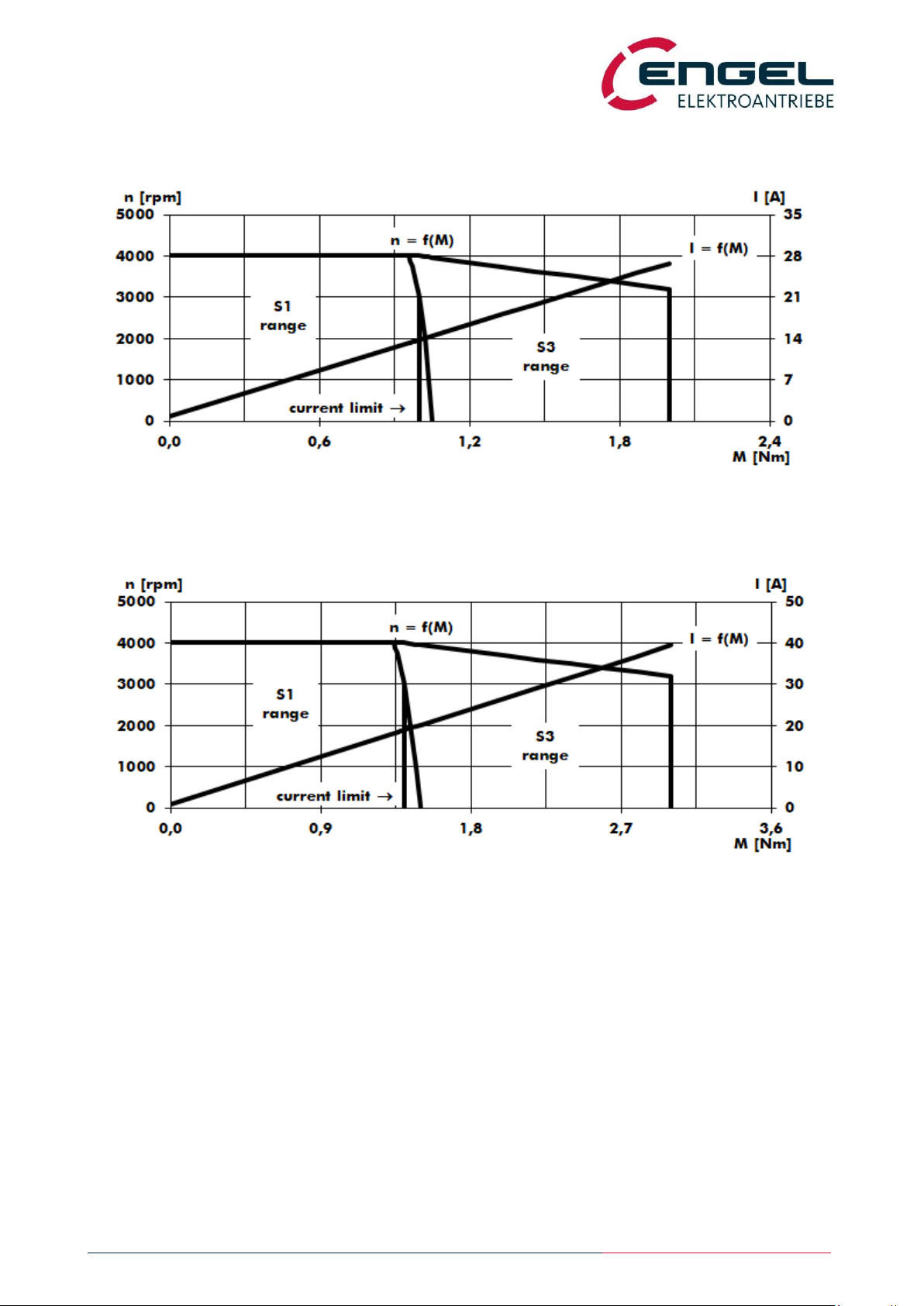
6.2.1 HFI2230 characteristics
Figure 6-1: HFI2230 characteristics, 24 V, 4000/5000 rpm
6.2.2 HFI2260 characteristics
Figure 6-2: HFI2260 characteristics, 24 V, 3000/4000 rpm
Integrated Synchronous Servo Drives
HFI 22xx / HFI 26xx / HFI 32xx / HFI 37xx
Technical Data - System Data HFI26xx
Operating Manual Rev. 1.3 www.engelantriebe.de Page 11
6.3 System Data HFI26xx
Designation
Unit
Value
additional information
HFI2630
HFI2660
Rated speed
min-1
4000
3000
Peak speed
min-1
5000
4000
Rated input current*1)
ADC
8.8 / 4.4
10.6 / 5.3
24V-Type/48V-Type
Rated motor current*2)
Aspk
13.2 / 6.8
17.9 / 8.9
24V-Type/48V-Type
Peak motor current*2)
Aspk
26.5 / 13.7
37.5 / 18.5
24V-Type/48V-Type
Motor current measurement
range
A
55.0 / 27.5
Rated power*3)
W
150
190
Rated torque*3)
Nm
0.36
0.61
Peak torque
Nm
0.75
1.30
Torque constant
Nm/A
0.030 / 0.058
0.036 / 0.073
24V-Type/48V-Type
Voltage constant
V/1kmin-1
3.6 / 7.0
4.4 / 8.8
24V-Type/48V-Type
Flange dimension
mm²
55 x 55
Drive length (without fieldbus
module)*4)
mm
136 / 166
166 / 196
without/with parking brake
Weight
kg
1.2 / 1.45
1.6 / 1.85
without/with parking brake
Parking Brake (optional):
automatically operated
Static braking torque
Nm
2.0
Power (electric)
W
10
*1) The rated input current is the direct current drawn in nominal operation (rated torque at rated speed) from the input
voltage (24 VDC or 48 VDC). The current drawn from the input voltage is proportional to the converted power, not to
be confused with the torque-building motor current, which is displayed as sine peak value in DSerV and is propor-
tional to the motor torque.
Please also observe that the supply line is lossy. This leads to a reduction in voltage and speed at the motor system
and to increased power consumption of the device. A connection line with a nominal cross-section of 1.5 mm² al-
ready has an overall loss resistance of approx. 2 x 12.5 mΩ/m (conductors and return conductors)! Appropriate pow-
er reserves must be provided in the supply!
*2) Motor phase current as a sine peak value, which is required for the generation of the rated or peak torque. Motor
phase current is displayed in DSerV. Not to be confused with the current taken from the supply.
*3) The specified values apply for the installation of the drive on a system surface made of aluminium (A = 0.1 m²,
d = 10 mm). It must be taken into consideration that the specified continuous output power must be derated for
thermally unfavourable couplings.
*4) With fieldbus module the length of the drive increases by 14 mm.
Integrated Synchronous Servo Drives
HFI 22xx / HFI 26xx / HFI 32xx / HFI 37xx
System Data HFI26xx - HFI2630 characteristics
Operating Manual Rev. 1.3 www.engelantriebe.de Page 12
6.3.1 HFI2630 characteristics
Figure 6-3: HFI2630 characteristics, 24 V, 4000/5000 rpm
6.3.2 HFI2660 characteristics
Figure 6-4: HFI2660 characteristics, 24 V, 3000/4000 rpm

Integrated Synchronous Servo Drives
HFI 22xx / HFI 26xx / HFI 32xx / HFI 37xx
Technical Data - System Data HFI32xx
Operating Manual Rev. 1.3 www.engelantriebe.de Page 13
6.4 System Data HFI32xx
Designation
Unit
Value
additional information
HFI3260
HFI3290
Rated speed
min-1
2600 / 3000
- / 3000
24V-Type/48V-Type
Peak speed
min-1
4000
Rated input current*1)
ADC
14.0 / 8.0
- / 10.8
24V-Type/48V-Type
Rated motor current*2)
Aspk
25.3 / 13.7
- / 18.9
24V-Type/48V-Type
Peak motor current*2)
Aspk
51.5 / 26.8
- / 39.5
24V-Type/48V-Type
Motor current measurement
range
A
75
Rated power*3)
W
260 / 315
440
Rated torque*3)
Nm
0.95 / 1.00
1.40
Peak torque
Nm
2.00
3.00
Torque constant
Nm/A
0.040 / 0.077
- / 0.078
24V-Type/48V-Type
Voltage constant
V/1kmin-1
4.8 / 9.3
- / 9.4
24V-Type/48V-Type
Flange dimension
mm²
65 x 65
Drive length (without fieldbus
module)*4)
mm
163 / 193
193 / 223
without/with parking brake
Weight
kg
2.1 / 2.4
2.7 / 3.0
without/with parking brake
Parking Brake (optional):
automatically operated
Static braking torque
Nm
3.5
Power (electric)
W
12
*1) The rated input current is the direct current drawn in nominal operation (rated torque at rated speed) from the input
voltage (24 VDC or 48 VDC). The current drawn from the input voltage is proportional to the converted power, not
to be confused with the torque-building motor current, which is displayed as sine peak value in DSerV and is pro-
portional to the motor torque.
Please also observe that the supply line is lossy. This leads to a reduction in voltage and speed at the motor system
and to increased power consumption of the device. A connection line with a nominal cross-section of 1.5 mm² al-
ready has an overall loss resistance of approx. 2 x 12.5 mΩ/m (conductors and return conductors)! Appropriate pow-
er reserves must be provided in the supply!
*2) Motor phase current as a sine peak value, which is required for the generation of the rated or peak torque. Motor
phase current is displayed in DSerV. Not to be confused with the current taken from the supply.
*3) The specified values apply for the installation of the drive on a system surface made of aluminium (A = 0.1 m²,
d = 10 mm). It must be taken into consideration that the specified continuous output power must be derated for
thermally unfavourable couplings.
*4) With fieldbus module the length of the drive increases by 14 mm.
Integrated Synchronous Servo Drives
HFI 22xx / HFI 26xx / HFI 32xx / HFI 37xx
System Data HFI32xx - HFI3260 characteristics
Operating Manual Rev. 1.3 www.engelantriebe.de Page 14
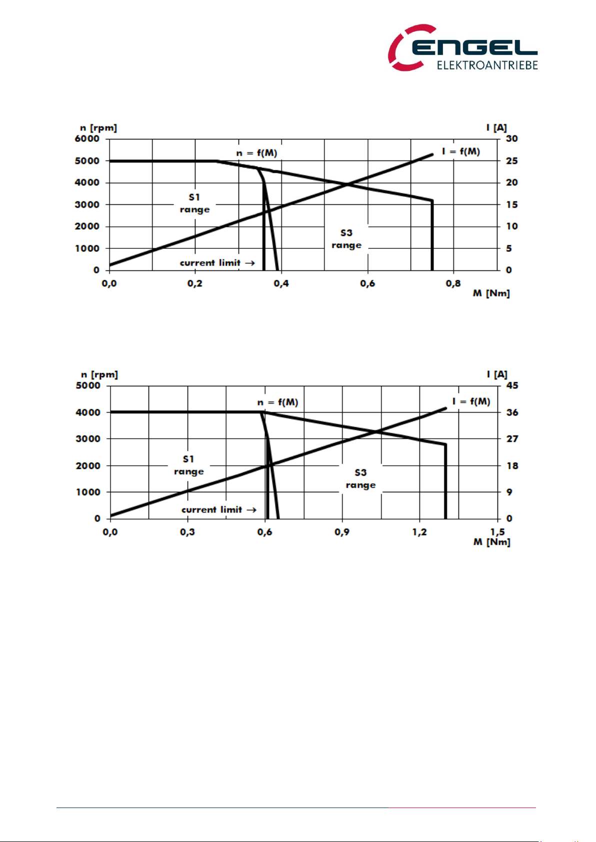
6.4.1 HFI3260 characteristics
Figure 6-5: HFI3260 characteristics, 48 V, 3000/4000 rpm
6.4.2 HFI3290 characteristics
Figure 6-6: HFI3290 characteristics, 48 V, 3000/4000 rpm

Integrated Synchronous Servo Drives
HFI 22xx / HFI 26xx / HFI 32xx / HFI 37xx
Technical Data - System Data HFI37xx
Operating Manual Rev. 1.3 www.engelantriebe.de Page 15
6.5 System Data HFI37xx
Designation
Unit
Value
additional information
HFI3760
HFI3790
Rated speed
min-1
3000
Peak speed
min-1
4000
Rated input current*1)
ADC
- / 10.7
- / 13.4
24V-Type/48V-Type
Rated motor current*2)
Aspk
- / 19.2
- / 23.9
24V-Type/48V-Type
Peak motor current*2)
Aspk
- / 40.0
- / 52.0
24V-Type/48V-Type
Motor current measurement
range
A
75
Rated power*3)
W
440
565
Rated torque*3)
Nm
1.4
1.8
Peak torque
Nm
3.00
4.00
Torque constant
Nm/A
- / 0.077
- / 0.079
24V-Type/48V-Type
Voltage constant
V/1kmin-1
- / 9.3
- / 9.5
24V-Type/48V-Type
Flange dimension
mm²
75 x 75
Drive length (without fieldbus
module)*4)
mm
168 / 198
198 /228
without/with parking brake
Weight
kg
2.95 / 3.5
3.8 / 4.15
without/with parking brake
Parking Brake (optional):
automatically operated
Static braking torque
Nm
3.5
Power (electric)
W
12
*1) The rated input current is the direct current drawn in nominal operation (rated torque at rated speed) from the input
voltage (24 VDC or 48 VDC). The current drawn from the input voltage is proportional to the converted power, not to
be confused with the torque-building motor current, which is displayed as sine peak value in DSerV and is propor-
tional to the motor torque.
Please also observe that the supply line is lossy. This leads to a reduction in voltage and speed at the motor system
and to increased power consumption of the device. A connection line with a nominal cross-section of 1.5 mm² al-
ready has an overall loss resistance of approx. 2 x 12.5 mΩ/m (conductors and return conductors)! Appropriate pow-
er reserves must be provided in the supply!
*2) Motor phase current as a sine peak value, which is required for the generation of the rated or peak torque. Motor
phase current is displayed in DSerV. Not to be confused with the current taken from the supply.
*3) The specified values apply for the installation of the drive on a system surface made of aluminium (A = 0.1 m²,
d = 10 mm). It must be taken into consideration that the specified continuous output power must be derated for
thermally unfavourable couplings.
*4) With fieldbus module the length of the drive increases by 14 mm.

Integrated Synchronous Servo Drives
HFI 22xx / HFI 26xx / HFI 32xx / HFI 37xx
System Data HFI37xx - HFI3760 characteristics
Operating Manual Rev. 1.3 www.engelantriebe.de Page 16
6.5.1 HFI3760 characteristics
Figure 6-7: HFI3760 characteristics, 48 V, 3000/4000 rpm
6.5.2 HFI3790 characteristics
Figure 6-8: HFI3790 characteristics, 48 V, 3000/4000 rpm

Integrated Synchronous Servo Drives
HFI 22xx / HFI 26xx / HFI 32xx / HFI 37xx
Important technical Information - Regenerative operation
Operating Manual Rev. 1.3 www.engelantriebe.de Page 17
6.6 Important technical Information
6.6.1 Regenerative operation
Attention!
Regenerative operation (generator mode) leads to an increase in operational voltage!
Observe permissible voltage values of the power supply and consumers connected in paral-
lel!
The device is equipped with an internal ballast circuit (brake chopper), which is capable of converting a low brake power
into heat for a short duration. Brake power conversion leads to a temperature rise in the motor system. Together with
the intermediate circuit (DC-link) capacity, dynamically occurring brake energies can be accommodated.
If the device operates quasi-statically in generator mode, suitable measures must be taken for the removal/conversion of
the energy (e.g. through an external ballast circuit).
Regenerated energy leads to an increase of the DC-link voltage, which is returned directly to the power connection of
the device and/or to the feeding direct current source (if necessary, provide a diode for the decoupling of the operating
voltage). The effect of the voltage increase when braking can be reduced, if necessary, by selecting a less abrupt, that is
a longer deceleration ramp.
If applicable, regenerated energy can be distributed to other loads connected to the supply voltage in parallel.
If regenerated braking energy cannot be converted, the terminal voltage rises until an overvoltage error (Error 4) is
triggered (see chapter 12.2 General error messages). The following voltage limits are specified in the devices:
Devices with 24 V operating voltage:
Ballast circuit working voltages: VBallast ON 30 V , VBallast OFF 27 V
Triggering of the overvoltage error: VError4 32 V
Devices with 48 V operating voltage:
Ballast circuit working voltages: VBallast ON 60 V , VBallast OFF 55 V
Triggering of the overvoltage error: VError4 65 V
6.6.2 Lead fuses
The device is not internally fused. A suitable external fuse must be provided (see chapter 10.2 Installation diagram and
chapter 8.5 I²t monitor).
6.6.3 Service life expectancy
The service life of the device is largely determined by the stress of the DC-link capacitors. With an ambient temperature
of 40 °C and motor current = motor rated current, a service life expectancy of approx. 15,000 h can be assumed. With
lower motor currents and/or lower ambient temperatures, higher service life expectancies arise.

Integrated Synchronous Servo Drives
HFI 22xx / HFI 26xx / HFI 32xx / HFI 37xx
Important technical Information - Safety installations
Operating Manual Rev. 1.3 www.engelantriebe.de Page 18
6.6.4 Safety installations
The device has extensive sensor equipment for the monitoring of the controller, power stage, motor and communication
with the outside. All occurring errors lead to the shut-down of the power stage (motor de-energised, no torque) and are
signalled by the red LED of the status display with a blinking code. Switching the power stage on again is only possible if
the cause of the error has been remedied and the error has been acknowledged by the control enable or –with fieldbus
control –has been reset via fieldbus.
The following safety functions are implemented:
The overcurrent/short-circuit monitor detects excessive current flow in the motor phases.
The I²t monitor protects the motor and power stage from thermal overload by limiting the motor current to
the rated current (see chapter 8.2.1.4 Parameters of the current control loop) after the lapse of a permissible
overload duration. The overload duration depends on various factors. For a detailed description of the I²t moni-
tor see chapter 8.5 I²t monitor.
The overvoltage monitor triggers as soon as the DC-link voltage exceeds a maximum permissible value (see
chapter 6.6.1 Regenerative operation).
The undervoltage monitor triggers as soon as the DC-link voltage falls below 18 V.
The temperature of the power stage is measured and the power stage is switched off when the temperature
exceeds 90 °C.
The signals of the internal angle sensor system are monitored for valid statuses. Invalid signal combina-
tions lead to the shut-down of the power stage.

Integrated Synchronous Servo Drives
HFI 22xx / HFI 26xx / HFI 32xx / HFI 37xx
DSerV service software - System requirements
Operating Manual Rev. 1.3 www.engelantriebe.de Page 19
7DSerV service software
The DSerV service software provides a simple and clearly laid out configuration of the devices. Important operating
statuses, such as speed, current, enable, etc. can be seen at a quick glance. Scalings, current limits and operating
modes are adjustable through menus. Device settings can be saved on the hard disk of the PC. The program language is
selectable: German/English.
7.1 System requirements
For the installation and operation of the DSerV service software, the following requirements apply:
PC/Laptop with Microsoft Windows XP, Windows 7, Windows 8, Windows 10
CDROM-Drive
RS232 serial interface (COM1 ... COM99):
On-Board or USB/RS232 converter, supported baud rate at least 115,2 kBaud
serial connection cable (see chapter 10.2 Installation diagram)
7.2 Installation and start-up of the program
Note!
Read the licence agreement on the provided data carrier of the software before installation.
With the installation of the DSerV service software, you agree to the conditions of the li-
cense agreement.
7.2.1 Installation of the software
For the installation of DSerV it is sufficient to copy the program files to a working directory:
1. Start WINDOWS.
2. Insert the CDROM with DSerV service software in an appropriate drive.
3. Start WINDOWS Explorer and display CDROM contents (main directory).
Alternative 1 (recommended):
4. Start the file DSerV.exe directly from the CDROM. An installation menu opens.
Note: The installation menu only opens, if DSerV.exe is started from a removable data carrier such as a
CDROM.
5. Follow the further instructions in the installation menu.
Alternative 2:
6. Manually copy the entire directory tree from the CDROM to a previously created working directory on the inter-
nal hard disk of the PC.
(This process can also be applied if the software was supplied in electronic form and not on CDROM.)
This manual suits for next models
11
Table of contents
Popular DC Drive manuals by other brands


Toshiba
Toshiba ATAPI installation manual

SOMFY
SOMFY Sonesse 40 RTS manual

ABB
ABB DCS800 Hardware manual

KB Electronic
KB Electronic KBVF Series Installation and Operation Manual Supplemental Information

American Control Electronics
American Control Electronics PAT450-10 quick start guide

Control Techniques
Control Techniques Commander SK Getting started guide

Lenze
Lenze AC Tech MCH Series Communications guide

Aura
Aura VENOM-8 owner's manual

ZIEHL-ABEGG
ZIEHL-ABEGG PMIcontrol Basic-M Series operating instructions

Emerson
Emerson Dixell XEV23D Installing and operating instructions

ABB
ABB ACS580MV quick guide

Rockwell Automation
Rockwell Automation Allen-Bradley PowerFlex 6000 user manual