manuals.online logo
Brands
  1. Home
  2. •
  3. Brands
  4. •
  5. Emerson
  6. •
  7. DC Drive
  8. •
  9. Emerson Dixell XEV23D Wiring diagram

Emerson Dixell XEV23D Wiring diagram

1592025930 XEV23D GB r1.0 07.10.2011.doc XEV23D 1/4
XEV23D
DRIVER FOR STEPPER ELECTRONIC EXPANSION
VALVES
--- MANUAL FOR RELEASE 1.2 ---
1. GENERAL WARNING.........................................................................................................................1
2. GENERAL DESCRIPTION..................................................................................................................1
3. WIRING CONNECTIONS ...................................................................................................................1
4. VALVE CONNECTIONS AND CONFIGURATION.............................................................................1
5. ABSOLUTE MAXIMUM POWER........................................................................................................1
6. FRONT PANEL ...................................................................................................................................2
7. USER INTERFACE.............................................................................................................................2
8. PARAMETER LIST .............................................................................................................................2
9. DIGITAL INPUTS ................................................................................................................................3
10. FORCED OPENING............................................................................................................................3
11. ELECTRICAL CONNECTIONS...........................................................................................................3
12. RS485 SERIAL LINE...........................................................................................................................3
13. HOW TO: USE THE HOT-KEY...........................................................................................................3
14. DISPLAY MESSAGES........................................................................................................................4
15. TECHNICAL DATA..............................................................................................................................4
16. STANDARD VALUES .........................................................................................................................4
1. GENERAL WARNING
1.1 PLEASE READ BEFORE USING THIS MANUAL
This manual is part of the product and should be kept near the instrument for easy and quick
reference.
The instrument shall not be used for purposes different from those described hereunder. It cannot
be used as a safety device.
Check the application limits before proceeding.
1.2 SAFETY PRECAUTIONS
Check the supply voltage is correct before connecting the instrument.
Do not expose to water or moisture: use the controller only within the operating limits avoiding
sudden temperature changes with high atmospheric humidity to prevent formation of condensation
Warning: disconnect all electrical connections before any kind of maintenance.
Fit the probe where it is not accessible by the End User. The instrument must not be opened.
In case of failure or faulty operation send the instrument back to the distributor or to “Dixell S.r.l.”
(see address) with a detailed description of the fault.
Consider the maximum current which can be applied to each relay (see Technical Data).
Ensure that the wires for probes, loads and the power supply are separated and far enough from
each other, without crossing or intertwining.
In case of applications in industrial environments, the use of mains filters (our mod. FT1) in
parallel with inductive loads could be useful.
2. GENERAL DESCRIPTION
The XEV23D module is able to drive a large variety of stepper electronic expansion valves. XEV23D
permits to regulate the superheat (SH) of the fluid that runs into refrigerating unit in order to obtain
optimized performance and a functioning of the evaporator independent by climatic or load conditions.
XEV23D modules are equipped with two probe inputs, one for 4 to 20mA or 0 to 5V pressure transducer
and another one for NTC-EU or NTC-US temperature probe. There are also two configurable digital
inputs, the first one is free of voltage and the other ones is free of voltage to pass from the chilling to
the heat-pump model. With the useful display it’s possible to see the value of superheat (SH), the
degree of opening of the valve or the probe values, the local keyboard allows to program the instrument
without any other devices. To complete instrument equipment, a RS485 serial link permits to connect
XEV23D to dIXEL monitoring and supervising systems.
3. WIRING CONNECTIONS
The superheat regulation is performed only when the cooling digital input is enabled. The following
scheme shows how the device takes the request of cooling:
Please see the following scheme to make the right wirings. With "First Level" are indicated the
connections on the floor of the 4 DIN module and, of course, with "Second Level" the connections of the
1st floor that are only for the stepper motor of the valve and for HOT-KEY.
4. VALVE CONNECTIONS AND CONFIGURATION
WARNINGS
1. To avoid possible problems, before connecting the valve configure the driver by making the
right changes on the parameters. Select the kind of motor (tEU parameter) and check if the
valve is present in tEP parameter table reported here below.
2. The max distance between an XM controller and a valve must not exceed 10 m. To avoid
any problems, use only shielded cables with section greater than or equal to 0.325 mm²
(AWG22).
tEP
Model
LSt
(steps*10)
uSt
(steps*10)
CPP
(mA*10)
CHd
(mA*10)
Sr
(step/s)
0
Manual settings
Par
Par
Par
Par
Par
1
Alco EX4-EX5-EX6
5
75
50
10
500
2
Alco EX7
10
160
75
25
500
3
Alco EX8 500
10
260
80
50
500
4
Danfoss ETS-25/50
7
262
10
10
300
5
Danfoss ETS-100
10
353
10
10
300
6
Danfoss ETS-250/400
11
381
10
10
300
7
Sporlan SEI 0.5-11
0
159
16
5
200
8
Sporlan SER 1.5-20
0
159
12
5
200
9
Sporlan SEI 30
0
319
16
5
200
10
Sporlan SER(I) G,J,K
0
250
12
5
200
11
Sporlan SEI 50
0
638
16
5
200
12
Sporlan SEH(I) 100
0
638
16
5
200
13
Sporlan SEH(I) 175
0
638
16
5
200
If you can see your valve on the table, please select the valve through tEP parameter. In this way, you
can be sure of a right configuration.
About the connection, please pay attention to the following table to have a quick reference on the
connection mode for valves of different manufacturer. In any case, the unique and valid reference has
to be considered the datasheet made by manufacturer of the valve:
4 WIRES VALVES (BIPOLAR)
Connection
numbering
ALCO EX
SPORLAN
SEI-SEH
DANFOSS
ETS
4
BLUE
WHITE
BLACK
2
BROWN
BLACK
WHITE
3
BLACK
RED
RED
1
WHITE
GREEN
GREEN
5-6 WIRES VALVES (UNIPOLAR)
Connection
numbering
SPORLAN
SAGINOMIYA
4
ORANGE
ORANGE
2
RED
RED
3
YELLOW
YELLOW
1
BLACK
BLACK
5 – Common
GRAY
GRAY
AFTER MAKING THE CONNECTION, PLEASE SWITCH OFF AND ON THE XEV CONTROLLER IN
ORDER TO BE SURE OF THE RIGHT POSITIONING OF THE VALVE.
5. ABSOLUTE MAXIMUM POWER
XEV23D is able to drive a wide range of stepper valves, in the following table are indicated the
maximum values of current that the actuator can supply to the stepper wiring. The dIXEL transformer to
use is the TF20D.
1592025930 XEV23D GB r1.0 07.10.2011.doc XEV23D 2/4
NOTE: the electrical power absorption of the valve can be unrelated to refrigeration power that valve
has. Before using the actuator, please read the technical manual of the valve supplied by the
manufacturer and check the maximum current used to drive the valve in order to verify that they are
lower than those indicated below.
VALVE
TYPE
BIPOLAR VALVES
(4 wires)
Maximum Current 0.9A
UNIPOLAR VALVES
(5-6 wires)
Maximum Current 0.33A
6. FRONT PANEL
To display and to modify the set point.
In programming mode it selects a
parameter or it confirms a value.
By pressing and releasing this key, it’s
possible to see the values of the
probes.
In programming mode it slides the
codes of the parameters or it
increases their values.
In programming mode it slides the
codes of parameters or it decreases
their values.
KEYS COMBINATIONS
+
To lock or to unlock
the keyboard
+
To enter
programming mode.
6.1 XEV23D LEDS
On display there are some luminous dots. Their meaning is described in the following table:
LED
MODE
Function
ON
Low pressure alarm
ON
Maximum Operating Pressure alarm
OFF
Valve is completely closed
BLINKING
Valve is moving
ON
Valve is completely opened
BLINKING
Serial communication present
OFF
Serial communication absent
ON
Superheat alarm
7. USER INTERFACE
7.1 HOW TO: SEE THE READ-ONLY VALUES
1) Press and release UP button.
2) First read-only label is showed;
3) Brows parameter labels with UP or DOWN buttons.
4) Press SET to see read-only value. To change parameter, press SET.
5) To leave the fast access menu, press and release SET+UP or wait for time-out to expire (about 3
minutes).
7.2 HOW TO: SEE THE SET POINT
1) Press the SET buttons until the set point will be showed.
2) To come back to see temperature, wait about 5s or press newly SET key.
7.3 HOW TO: MODIFY THE SET POINT
To change the set point value operate as follows:
1) Press the SET button until the set point will be showed.
2) Use UP or DOWN buttons to change its value.
3) Press SET button to store the new value.
7.4 HOW TO: ENTERING “PR1” PARAMETER MENU
To enter in “Pr1” level menu:
1) Pressing SET+DOWN buttons for about 3 seconds.
2) Instruments shows first parameter in Pr1 menu
7.5 HOW TO: ENTERING “PR2” PARAMETER MENU
To enter to “Pr2” parameters list:
1. Enter to “Pr1”.
2. Select “Pr2” parameter and press SET.
3. The “PAS” label will be shown, then “0--” with
0 blinking.
4. Insert “321” password through UP and
DOWN buttons,then press SET to confirm.
7.6 HOW TO: CHANGE A PARAMETERS VALUE
To change the parameter’s value operate as
follows:
1. Enter the Programming mode by pressing
the Set and DOWN button for about 3s.
2. Select the required parameter.
3. Press the SET button to display the value.
4. Use UP or DOWN to change the value.
5. Press SET to store the new value and move to the following parameter.
To exit: Press SET + UP or wait 30s without pressing any button.
NOTE: the set value is stored even when the procedure is exited by waiting the time-out to expire.
8. PARAMETER LIST
NOTE: All pressure parameters are relatives or absolutes depending on the PrM parameter
REGULATION
SEt
SH Set point in Chill mode (0,0 ÷ 24,0°C - 0 ÷ 43 °F)
St2
SH Set point in Heat Pump mode (0,0 ÷ 24,0°C - 0 ÷ 43 °F)
FtY
Kind of gas: (R22, 134, 404, 407, 410, 507, CO2) type of gas used by plant. This is a
fundamental parameter for correct functioning of all system.
PEo
Probe Error opening percentage: (0 to 100%) if a temporary probe error occurs, valve
opening percentage is PEo until PEd time is elapsed. If PEO is different from 0 it
assures cooling also with probe error, because even if the device cannot calculate
superheat the valve can work at PEo percentage.
PEd
Probe Error delay before stopping regulation: (0 to 239sec; 240=On=unlimited) if
probe error duration is higher than PEd, valve will close completely and “Pf” message
will be showed. With PEd=on, valve opening is PEo until probe error finishes.
tEU
Type of Stepper motor: (UP; bP) it permits to select the kind of valve. UP = 5-6 wires
unipolar valves; bP = 4 wires bipolar valves. !!!!! WARNING !!!!! by changing this
parameter the valve has to be reinitialized.
tEP
Predefined valve selection: (0 to 13) if tEP=0 the user has to modify all the parameters
of configuration in order to use the valve. If tEP is different from 0 the device performs a
fast configuration of the following parameters: LSt,USt,Sr,CPP,CHd. To select the
right number please read the following table:
tEP
Model
LSt
(steps*10)
uSt
(steps*10)
CPP
(mA*10)
CHd
(mA*10)
Sr
(step/s)
0
Manual settings
Par
Par
Par
Par
Par
1
Alco EX4-EX5-EX6
5
75
50
10
500
2
Alco EX7
10
160
75
25
500
3
Alco EX8 500
10
260
80
50
500
4
Danfoss ETS-25/50
7
262
10
10
300
5
Danfoss ETS-100
10
353
10
10
300
6
Danfoss ETS-250/400
11
381
10
10
300
7
Sporlan SEI 0.5-11
0
159
16
5
200
8
Sporlan SER 1.5-20
0
159
12
5
200
9
Sporlan SEI 30
0
319
16
5
200
10
Sporlan SER(I) G,J,K
0
250
12
5
200
11
Sporlan SEI 50
0
638
16
5
200
12
Sporlan SEH(I) 100
0
638
16
5
200
13
Sporlan SEH(I) 175
0
638
16
5
200
If tEP is different from 0, previous configuration of LSt,uSt,Sr,CPP and CHd will be overwritten.
HFS
Kind of motor movement: (HAF; FUL)
HAF = half step. Use this setting for the unipolar valve.
FUL = half step. Use this setting for the bipolar valve.
LSt
Minimum number of steps: (0 to USt (*10)) it permits to select the minimum number of
steps. At this number of steps the valve should be closed. So it’s necessary the reading
of manufacturer datasheet to set correctly this parameter. It’s the minimum number of
steps to stay in advised range of functioning. !!!!! WARNING !!!!! after changing this
parameter the valve will have to be reinitialized. The device performs this
procedure automatically and restarts its normal functioning when the
programming mode ends.
USt
Maximum number of steps: (LSt to 800 (*10)) it permits to select the maximum number
of steps. At this number of steps the valve should be completely opened. Read the
datasheet provided by manufacturer of the valve to set correctly this parameter. It’s the
maximum number of steps to stay in advised range of functioning. !!!!! WARNING !!!!!
after changing this parameter the valve will have to be reinitialized. The device
performs this procedure automatically and restarts its normal functioning when
the programming mode ends.
ESt
Extra step in closing phase: (0 to 255 (*10)) it sets the number of extra steps the
controller performs, when the valve is closed at start up, to force the closure of the valve.
Sr
Step rate: (10 to 600 step/sec) it is the maximum speed to change step without losing
precision (=losing steps). It’s advised to stay under the maximum speed.
CPP
Current per phase (only bipolar valves): (0 to 100 (*10mA)) it is the maximum current
per phase used to drive valve. It’s used only with bipolar valves.
CHd
Holding current per phase (only bipolar valves): (0 to 100 (*10mA)) it is the current
per phase when the valve is stopped for more than 4 minutes. It’s used only with
bipolar valves.
oPE
Start opening Percentage: (0 to 100%) opening valve percentage when start function is
active and during post defrost phase. This phase duration is SFd time.
SFd
Start Function duration: (0.0 to 42min 00s, res. 10s) it sets start function duration and
post-defrost duration. During this phase the alarms are neglected.
MnF
Maximum opening percentage at normal Functioning: (0 to 100%) during regulation
it sets the maximum valve opening percentage.
1592025930 XEV23D GB r1.0 07.10.2011.doc XEV23D 3/4
FoP
Forced Opening percentage: (0 to 100; nU) if FoP=nU valve works with regulation
algorithm. If FoP is different from nU the valve stays at FoP opening percentage. This
function could be useful during plant starting or during service operations.
PID PARAMETERS (trained staff)
Pb
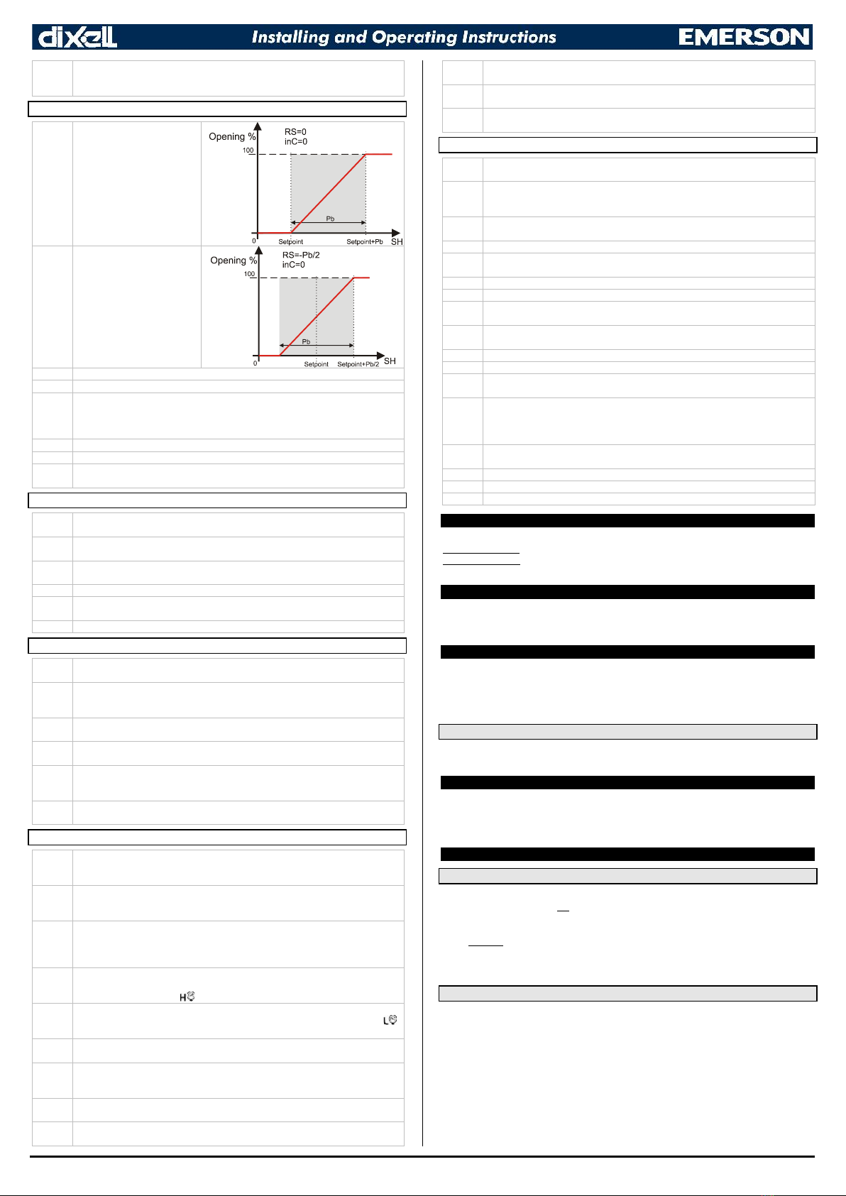
Proportional band in chill
mode:
(0.1 to 50.0°C; 1 to 90°F)
PI proportional band. A value
bigger than 5°C is advised.
rS
Band Offset:
(-12.0 to 12.0°C; -21 to 21°F)
PI band offset. It permits to
move the proportional band of
the PI. With rS=0 the band is
between [SEt to SEt+Pb].
inC
Integration time in chill mode: (0 to 255s) PI integration time.
dFc
Derivative time in chill mode: (0 to 255s) PID derivative time.
Pb2
Proportional band in heat-pump mode:
(0.1 to 50.0°C; 1 to 90°F)
PI proportional band. A value bigger than 5°C is advised.
it2
Integration time in heat-pump mode: (0 to 255s) PI integration time.
dt2
Derivative time in heat-pump mode : (0 to 255s) PID derivative time.
db
Dead band: (0.0 ÷ 25.5 °C; 0 ÷ 45°F) if the superheat is inside the band SH-db/2÷
SH+db/2 the position of the valve is not updated
PROBE PARAMETERS
tPP
Type of Pressure transducer: (420; 5V) it sets type of pressure transducer to use. 420
= 4 to 20mA pressure transducer; 5V = 0 to 5V ratiometric transducer.
PA4
Probe value at 4mA or at 0V: (-1.0 to P20 bar; -14 to P20 psi) pressure value
measured by probe at 4mA or at 0V (related to PrM parameter).
P20
Probe value at 20mA or at 5V: (PA4 to 50.0 bar; PA4 to 725 psi) pressure value
measured by probe at 20mA or at 5V (related to PrM parameter).
oPr
Pressure probe calibration: -12.0 to 12.0 bar; -174 to 174 psi.
ttE
Type of temperature probe: (PtM; ntC) it allows to set the kind of probe used by the
instrument: PtM = PT1000 probe, ntC = NTC-US probe.
otE
Temperature probe calibration: -12.0 to 12.0°C; -21 to 21°F.
DIGITAL INPUTS
i1P
Digital Input 1 (Free of voltage) digital input polarity: (cL, oP) CL = activated when
closed; oP = activated when opened.
i1F
Digital Input 1 (Free of voltage) digital input function: (CCL, rL)
-CCL = cooling call;
-rL = digital input activates relay.
d1d
Digital Input 1 (Free of voltage) activation delay: (0 to 255 min) this activation delay is
used only if digital input is configured as rL.
i2P
Digital Input 2 (Free of voltage) digital input polarity: (CL, oP) CL = activated when
closed; oP = activated when opened.
i2F
Digital Input 2 (Free of voltage) digital input function: (CCL, P-C)
- CCL = cooling call;
- P-C = Switch form chiller to heat pump mode.
d2d
Digital Input 2 (High voltage) activation delay: (0 to 255 min) this activation delay is
used only if digital input is configured as rL.
ALARM
dAo
Alarm delay after restarting regulation: (0.0 to 42min 00s, res. 10s) time between
digital input activation (configured as CCL) and alarm signalling. The LSH alarm is
always signalled also during this time.
tdA
Type of alarm signalled by relay: (ALL, SH, PrE, di) ALL = all alarm; SH = superheat
alarm; PrE = pressure alarm; di = activation only when digital input configured as rL is
active.
LPL
Lower Pressure Limit for superheat regulation: (PA4 to P20 bar; PA4 to P20 psi)
when suction pressure comes down to LPL, the regulation is performed with a LPL fixed
value for pressure. When suction pressure comes back to LPL, the normal pressure
value is used (related to PrM parameter).
MoP
Maximum Operating Pressure threshold: (LoP to P20bar; LoP to P20 psi) if suction
pressure exceeds maximum operating pressure value, the instrument signals this
situation with an alarm LED (related to PrM parameter).
LoP
Lowest Operating Pressure: (PA4 to MoP bar; PA4 to MoP psi) if the suction pressure
comes down to this value, a low pressure alarm will be signalled with an alarm LED
(related to PrM parameter).
PHY
Pressure alarm Hysteresis: (0.1 to 5.0 bar, 1 to 72 psi) pressure hysteresis to disable
alarm signalling.
dML
Delta MoP-LoP: (0 to 100%) when a MoP alarm occurs valve will close of the dML
percentage every one second until MoP alarm is active. When LoP occurs, valve will
open of the dML percentage every one second until LoP alarm is active.
MSH
Maximum SuperHeat alarm: (LSH to 80.0°C; LSH to 144°F) when superheat exceeds
this value, an high superheat alarm will be signalled after interval SHd.
LSH
Lowest SuperHeat alarm: (0.0 to MSH°C; 0 to MSH°F) when superheat goes down to
this value a low superheat alarm is signalled after interval SHd.
SHY
SuperHeat alarm Hysteresis: (0.0 to 25.5°C; 1 to 77°F) hysteresis for superheat alarm
deactivation.
SHd
SuperHeat alarm activation delay: (0 to 255 s) when a superheat alarm occurs, the
delay time SHd have to expire before signalling this alarm.
FrC
Fast-recovery Constant: (0 to 100 s) permits to increase integral time when SH is
below the set-point. If FrC=0 fast recovery function is disabled.
DISPLAY
Lod
Local display: (SH; PEr; P1; P2) SH = superheat; PEr = valve opening percentage;
P1 = value of temperature measured; P2 = pressure measured by P2 probe.
CF
Temperature measurement units: (°C; °F) °C= Celsius degree; °F = Fahrenheit
degree. NOTE: by changing measurement unit, the regulation parameters have to be
correctly changed.
PMU
Pressure Measurement units: (bAr, PSi) bAr = bar; PSi = psi. NOTE: by changing
measurement unit, the regulation parameters have to be correctly changed.
rES
Resolution (only °C): (dE; in) dE = decimal format; in = integer format.
PrM
Pressure visualization Mode: (rEL; AbS) rEL = relative pressure; AbS = absolute
pressure. All pressure parameters depend on this parameter.
CLP
Cooling Percentage (read only): Display the cooling percentage.
tP1
Temperature Probe value (read only): it shows temperature probe value from P1.
PPr
Pressure probe value (read only): it shows pressure probe value. The value depends
on PrM.
tP2
Temperature from P2 (read only): it shows temperature obtained from conversion of
pressure value.
oPP
Opening Percentage (read only): it shows the actual opening percentage of the valve.
d1S
Free of voltage digital input State (read only): it shows the free of voltage digital input.
d2S
High voltage digital input State (read only): it shows the high voltage digital input
state.
Mod
ModBus: (AdU; Std) AdU = (Only for XWEB systems) in this case XEV and
thermostatic controller are considered an alone instrument (it requires a custom library
for XWEB); Std = to use XEV in stand-alone mode, in this case normal Modbus-RTU
protocol is used.
Adr
RS485 Serial Address: (1 to 247) Identifies the instrument address when connected to a
ModBUS compatible monitoring system.
Ptb
Parameters map: (read only) it identifies parameters map written by factory.
rEL
Release Firmware: (read only) it shows firmware release.
Pr2
Second level menu.
9. DIGITAL INPUTS
The device is provided with two digital inputs.
The first one (13-15) is free of voltage and is used to enable the regulation
The second one (8-9) is free of voltage and is used to switch form chiller to heat-pump mode.
One of these inputs must be configured as cooling call.
10. FORCED OPENING
If necessary, by changing FoP parameter it’s possible to force the valve opening. For example, by
setting FoP=50 the valve will be open at half of full scale. To disable this function it’s necessary to
set FoP=nU (default value). The valve opening is enabled only when CCL digital input is enabled.
11. ELECTRICAL CONNECTIONS
The instrument is provided with pluggable screw terminal block to connect cables with a cross section
up to 2.5 mm2. Heat-resistant cables have to be used. Before connecting cables make sure the power
supply complies with the instrument’s requirements. Separate the probe cables from the power supply
cables, from the outputs and the power connections. Do not exceed the maximum current allowed on
each relay, in case of heavier loads use a suitable external relay.
11.1 PROBES
Temperature probe placement: between hour 3 and 9 respect to horizontal pipe section. For suction
pressure probe there aren’t any particular prescriptions
12. RS485 SERIAL LINE
All models can be connected to the monitoring and supervising system XWEB3000. If Mod=Std
standard ModBUS-RTU protocol is used, if Mod=AdU custom XWEB library is required. This last
configuration makes possible to use the same serial address of the thermostat that gives the cooling
request to XEV. In this way, it’s possible to reduce the number of addresses used.
13. HOW TO: USE THE HOT-KEY
13.1 PROGRAM A HOT-KEY FROM THE INSTRUMENT (UPLOAD)
1) Program one controller with the front keypad.
2) When the controller is ON, insert the HOT-KEY and push UP button; the “uPL” message
appears followed a by flashing “End”.
3) Push SET button and the “End” will stop flashing.
4) Turn OFF the instrument, remove the HOT-KEY and then turn it ON again.
NOTE: the “Err” message is displayed in case of any failed programming operation. In this case, push
again UP button if you want to restart the upload again or remove the HOT-KEY to abort the operation.
13.2 PROGRAM AN INSTRUMENT USING A HOT KEY (DOWNLOAD)
1) Turn OFF the instrument.
2) Insert a pre-programmed HOT-KEY into the 5-PIN connector and then turn the Controller ON.
3) Automatically the parameter list present into the HOT-KEY will be downloaded into the Controller
memory. The “doL” message will blink during this operation, followed a by a flashing “End” label.
4) After 10 seconds the instrument will restart working with the new parameters.
5) Remove the HOT-KEY.
NOTE: the “Err” message is displayed in case of any failed programming operation. In this case, push
again UP button if you want to restart the upload again or remove the HOT-KEY to abort the operation.
1592025930 XEV23D GB r1.0 07.10.2011.doc XEV23D 4/4
14. DISPLAY MESSAGES
Mess.
Cause
Outputs
“nA”
None of digital inputs configured as CCL are
activated
Valve closed
“PF”
The Ped time is elapsed and the regulation is
stopped
Valve closed after PEd. There is a probe
error
“P1”
Temperature probe fault
According to PEo and PEd.
“P2”
Pressure transducer fault
According to PEo and PEd.
“HSH”
High superheat alarm
By PI
“LSH”
Low superheat alarm
Valve Closed
“LPL”
Low pressure limit
see LPL parameter
“MoP”
Maximum Operating Pressure
see dML parameter
“LoP”
Lowest Operating Pressure
see dML parameter
“StF”
Start Function enabled
see SFd parameter
“StP”
Regulation stop caused by Std and Sti
Valve closed
“EE”
Memory error
-
14.1 ALARM RECOVERY
Probe alarms “P1”, “P2” start few seconds after the fault in the probe; they automatically stop few
seconds after the probe restarts normal operation. Check connections before replacing the probe. Max.
And min. Alarms “HSH”, “LSH”, “MoP” and “LoP” automatically stop as soon as the variable returns to
normal values.
The instrument is provided with an internal check verifying memory integrity. Alarm “EE” will flash when
a failure in the internal memory is detected. In such case call the service.
15. TECHNICAL DATA
Housing: self extinguishing ABS.
Case: 4 DIN modules 70x135mm with male and female connectors; depth 60mm.
Mounting: DIN RAIL mounted in an omega (3) din rail.
Protection: IP20.
Connections: pluggable screw terminal block 2.5 mm2wiring.
Power supply: 24Vac/dc ±10%.
Power absorption: depending on connected valve 20VA max.
Display: three digits with icons, red LEDs, height 14.2 mm.
Inputs: 1 temperature probe:
PT1000 probe: -50 to 110°C (-58 to 230°F).
NTC probe: -40 to 110°C (-40 to 230°F).
1 pressure transducer: 4 to 20mA or 0 to 5V.
Digital inputs: Digital input 1 (15-13): free of voltage.
Digital input 2 (8-9): free of voltage.
Outputs for valve: bipolar or unipolar valves.
Data storage: on the non-volatile memory (EEPROM).
Kind of action: 1B.
Pollution degree: normal.
Software Class: A.
Operating temperature: 0 to 55°C (32 to 131°F).
Storage temperature: -25 to 60°C (-13 to 140°F).
Relative humidity: 20 to 85% (no condensing).
Resolution: 0.1°C or 1°F.
Precision a 25°C (77°F): ±0.7°C ±1digit.
16. STANDARD VALUES
Label
Description
Range
Default
Level
Set
SH set point in chiller mode
0,0÷24,0°C; 0÷43°F
6.0
-
Set
SH set point in heat pump mode
0,0÷24,0°C; 0÷43°F
6.0
-
FtY
Kind of gas
R22; 134; 404; 407;
410; 507; Co2
407
Pr1
Peo
Probe Error opening percentage
0 to 100 %
50
Pr1
Ped
Probe Error delay before stopping regulation
0 to 239 s; on
on
Pr1
tEU
Type of Stepper motor
uP; bP
bp
Pr1
tEP
Automatic Valve configuration
0 to 10
nu
Pr1
HFS
Kind of driving
HAF; FUL
FUL
Pr1
LSt
Minimum number of steps
0; USt (*10)
0
Pr1
USt
Maximum number of steps
LSt to 800 (*10)
0
Pr1
ESt
Extra steps in closing phase
0 to 255 (*10)
0
Pr1
Sr
Step rate
10 to 600 step/s
10
Pr1
CPP
Current per phase (only bipolar valves)
0 to 100 (*10mA)
0
Pr1
CHd
Holding current per phase (only bipolar
valves)
0 to 100 (*10mA)
0
Pr1
oPE
Start opening Percentage
0 to 100 %
85
Pr1
SFd
Start Function duration
0.0 to 42min 00s, res. 10s
1.3
Pr1
MnF
Maximum opening percentage
0 to 100 %
100
Pr1
FoP
Forced Opening time-out
0 to 100 %; nU
nu
Pr1
PI PARAMETERS (trained staff)
Pb
Proportional band, chiller mode
[0.1 to 50.0°C]
[1 to 90°F]
10.0
Pr1
rS
Band Offset
[-12.0 to 12.0°C]
[-21 to 21°F]
0.0
Pr1
inC
Integration time chiller mode
0 to 255 s
120
Pr1
dFc
Derivative time chiller mode
0 to 255 s
0
Pr1
Pb2
Proportional band. Heat pump mode
[0.1 to 50.0°C]
[1 to 90°F]
10.0
Pr1
It2
Integration time Heat pump mode
0 to 255 s
120
Pr1
dt2
Derivative time Heat pump mode
0 to 255 s
0
Pr1
db
Dead band width
[0.1 to 50.0°C]
[1 to 90°F]
5.0
Pr1
PROBE PARAMETERS
tPP
Type of pressure transducer
420; 5V;
420
Pr1
PA4
Probe value at 4mA or at 0V (related to PrM
parameter)
[-1.0 to P20 bar]
[-14 to P20 psi]
0
Pr1
P20
Probe value at 20mA or at 5V (related to PrM
parameter)
[ PA4 to 50.0 bar]
[PA4 to 725 psi]
30
Pr1
oPr
Pressure probe calibration
[-12.0 to 12.0 bar]
[-174 to 174 psi]
0
Pr1
ttE
type of temperature probe
PT1000; ntC
Ntc
Pr1
otE
Temperature probe calibration
[-12.0 to 12.0°C]
[-21 to 21°F]
0.0
Pr1
DIGITAL INPUTS
i1P
Free of voltage digital input polarity
CL; oP
CL
Pr1
i1F
Free of voltage digital input function
CCL; rL
CCL
Pr1
d1d
Digital input 1 (free of voltage) activation delay
0 to 255 min
0
Pr1
i2P
Main voltage digital input polarity
CL; oP
CL
Pr1
i2F
Main voltage digital input function
CCL, rL
CCL
Pr1
d2d
Digital input 2 (Main voltage) activation delay
0 to 255 min
0
Pr1
ALARMS
dAo
Alarm delay after restarting regulation
0.0 to 42min 00s, res. 10s
10.0
Pr1
tdA
Type of alarm signalled by relay
ALL; SH; PrE; Di
ALL
Pr1
LPL
Lower pressure limit for superheat regulation
(related to PrM parameter)
[PA4 to P20 bar]
[PA4 to P20 psi]
n
Pr1
MoP
Maximum operating pressure threshold
(related to PrM parameter)
[LoP to P20 bar]
[LoP to P20 psi]
0.5
Pr1
LoP
Minimum suction pressure limit (related to PrM
parameter)
[PA4 to MoP bar]
[PA4 to MoP psi]
11.0
Pr1
PHy
Pressure alarm Hysteresis
[0.1 to 5.0 bar]
[1 to 72 psi]
0.5
Pr1
dML
delta MoP-LoP
0 to 100%
0.1
Pr1
MSH
Maximum superheat alarm
[LSH to 80.0°C]
[LSH to 176°F]
30
Pr1
LSH
Lowest superheat alarm
[0.0 to MSH°C]
[0 to MSH°F]
80.0
Pr1
SHY
Superheat hysteresis
[0.1 to 25.5°C]
[1 to 77°F]
2.5
Pr1
SHd
Superheat alarm activation delay
0 to 255 s
0.1
Pr1
FrC
Fast-Recovery Constant
0 to 100 s
120
Pr1
DISPLAY
50
Pr1
Lod
Local display
SH; PEr; P1; P2
SH
Pr1
CF
Temperature measurement units
°C; °F
°C
Pr1
PMu
Pressure measurement unit
bAr; PSi
bar
Pr1
rES
Resolution (only °C)
dE; in
De
Pr1
PrM
Type of pressure (Absolute / relative)
rEL; AbS
Rel
Pr1
CLP
Cooling call percentage
Read only
---
Pr1
tP1
Temperature probe value
Read only
---
Pr1
PPr
Pressure probe value
Read only
---
Pr1
tP2
Temperature converted from pressure probe
Read only
---
Pr1
oPP
Acutal Opening percentage
Read only
---
Pr1
d1S
Free of voltage digital input state
Read only
---
Pr1
d2S
Main voltage digital input state
Read only
---
Pr1
Mod
Modbus type
Std; AdU
---
Pr1
Adr
Serial address
1 to 247
1
Pr1
Ptb
Parameters map
---
1
Pr1
rEL
Release software
---
1.2
Pr1
Pr2
Second level menu
---
---
-

Other Emerson DC Drive manuals

Emerson Control Techniques Epsilon Ei User manual

Emerson

Emerson Control Techniques Epsilon Ei User manual

Emerson EVH Series User manual

Emerson

Emerson EVH Series User manual

Emerson Mentor MP Supplement

Emerson

Emerson Mentor MP Supplement

Emerson Unidrive HS72 User manual

Emerson

Emerson Unidrive HS72 User manual

Emerson Unidrive M700 Installation and operating instructions

Emerson

Emerson Unidrive M700 Installation and operating instructions

Emerson Quantum MP User manual

Emerson

Emerson Quantum MP User manual

Emerson Mentor MP Assembly instructions

Emerson

Emerson Mentor MP Assembly instructions

Emerson EV3 Series Instruction Manual

Emerson

Emerson EV3 Series Instruction Manual

Emerson unidrive sp User manual

Emerson

Emerson unidrive sp User manual

Emerson EV2000 Series User manual

Emerson

Emerson EV2000 Series User manual

Emerson Unidrive M200-01100017 User manual

Emerson

Emerson Unidrive M200-01100017 User manual

Emerson unidrive sp Instruction Manual

Emerson

Emerson unidrive sp Instruction Manual

Emerson E300 Series Guide

Emerson

Emerson E300 Series Guide

Emerson Mentor MP Assembly instructions

Emerson

Emerson Mentor MP Assembly instructions

Emerson Control Techniques Focus 3N User manual

Emerson

Emerson Control Techniques Focus 3N User manual

Emerson PACMotion VFD Series User manual

Emerson

Emerson PACMotion VFD Series User manual

Emerson E Series User manual

Emerson

Emerson E Series User manual

Emerson Bettis RTS User manual

Emerson

Emerson Bettis RTS User manual

Emerson Copeland EVM Series User manual

Emerson

Emerson Copeland EVM Series User manual

Emerson EV3150B Instruction Manual

Emerson

Emerson EV3150B Instruction Manual

Emerson Control Techniques EN Series User manual

Emerson

Emerson Control Techniques EN Series User manual

Emerson Unidrive M700 User manual

Emerson

Emerson Unidrive M700 User manual

Emerson COPELAND EVA3 Manual

Emerson

Emerson COPELAND EVA3 Manual

Emerson PACMotion VFD Series User manual

Emerson

Emerson PACMotion VFD Series User manual

Popular DC Drive manuals by other brands

Altec ID Drive user manual

Altec

Altec ID Drive user manual

Ismatec BVP Standard operating manual

Ismatec

Ismatec BVP Standard operating manual

Wesa ST Series operating manual

Wesa

Wesa ST Series operating manual

ABB ACH580-01 Series Quick installation and start-up guide

ABB

ABB ACH580-01 Series Quick installation and start-up guide

Eaton PowerXL DB1 installation manual

Eaton

Eaton PowerXL DB1 installation manual

ABB F-ARI Test manual

ABB

ABB F-ARI Test manual

American Control Electronics PWL440-10-JOG quick start guide

American Control Electronics

American Control Electronics PWL440-10-JOG quick start guide

Dover DE-STA-CO RD Series Service manual

Dover

Dover DE-STA-CO RD Series Service manual

TR-Electronic encoTRive MP Series Safety manual

TR-Electronic

TR-Electronic encoTRive MP Series Safety manual

Danfoss VLT 2800 Series operating instructions

Danfoss

Danfoss VLT 2800 Series operating instructions

Power Electronics SD750 Series Hardware and installation manual

Power Electronics

Power Electronics SD750 Series Hardware and installation manual

Danfoss AKD 2800 Quick setup

Danfoss

Danfoss AKD 2800 Quick setup

Danfoss VLT DriveMotor FCP 106 operating instructions

Danfoss

Danfoss VLT DriveMotor FCP 106 operating instructions

Pro-dig T12K instruction manual

Pro-dig

Pro-dig T12K instruction manual

LinMot E1100 Series user manual

LinMot

LinMot E1100 Series user manual

Danfoss AME 685 operating guide

Danfoss

Danfoss AME 685 operating guide

Somati system 1RM1 instruction manual

Somati system

Somati system 1RM1 instruction manual

Danfoss VLT HVAC instruction manual

Danfoss

Danfoss VLT HVAC instruction manual

manuals.online logo
manuals.online logoBrands
  • About & Mission
  • Contact us
  • Privacy Policy
  • Terms and Conditions

Copyright 2025 Manuals.Online. All Rights Reserved.