Page 1-2 June 13, 2005
A. INSTALLATION
In selecting a location for the line, consider these factors:
•Working weight (including oil tank filled to capacity) in relation to the building structure for
proper support.
•Access to the selected location where the machine will be installed.
•An adequate area to allow sufficient working space around the machine (a clearance of
at least 3 feet or 914 mm) for proper ventilation and maintenance.
Some thought should also be given to availability of the required power source (refer to the
electrical drawing shipped with the machine or in the back of the manual). The machine
should also be located away from grinding machines, sanding machines, spray painting areas
and other sources of contamination if practical.
Answers to questions regarding site preparation and other technical assistance is available
free of charge via telephone between the hours of 8 AM and 4:30 PM CST Monday through
Friday by calling the Engel Customer Service Department at 314-638-0100.
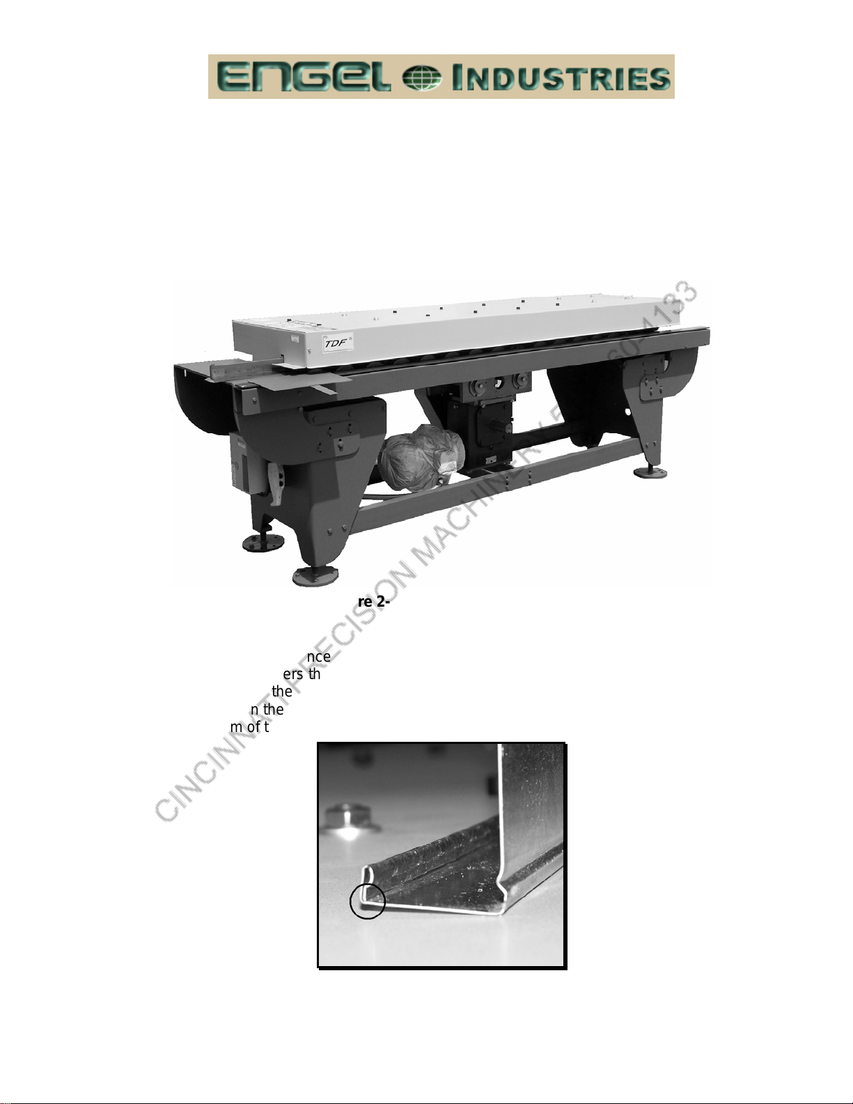
(1) Unpacking The Machine
When the machine arrives, inspect it carefully before accepting the shipment. It is
important to note any damage on the Bill of Lading or other shipping documents so that a
claim can be filed with the carrier.
Pay special attention to the control console, because it contains delicate electronic
devices. Check for physical damage to the switches and the components inside. If
anything looks damaged, notify both the carrier (to file a claim) and our Customer Service
Department (to order replacement parts). It is important to notify the factory promptly so
the new parts arrive before the machine is installed, as it may not be possible to start up
and run the machine without them.
Normal procedures should be used to unpack the machine. Remove any covering, steel
strapping or skids that may be present. Remove all wooden blocks (used as spacers to
prevent movement of the machine parts during shipment). After inspection and
unpacking, prepare to move the machine into position, using the floor layout drawing in
the back of this manual. This can be done with a fork truck or overhead crane. Once the
equipment is in position, fill the hydraulic tank with Mobile Dte 25 hydraulic oil (or
equivalent) if applicable and make the necessary electrical connections. Then bring in the
required power source to the main control console. When doing the electrical hookups,
refer to the electrical drawings supplied with the equipment if necessary.
To safely operate this machinery, all personal must read and understand the safety
section of this manual. Study and follow the safety precautions in this section, which are
intended to prevent injury to you and your fellow workers. However, they cannot cover all
possible situations. Therefore, consider the consequences of your actions before
executing any procedure or operation.
B. SAFETY
(1) Safety Precautions (Before Starting The Machine)
¾Protect yourself. Wear safety glasses and leather gloves while handling the material.
Do not wear loose clothing, neckties, or jewelry. If long sleeves must be worn, avoid
cuffs and buttons.