HSB Gamma 90-ZSSD Quick guide

HSB Automation GmbH
In Laisen 74
72766 Reutlingen
Germany
Tel. +49 7121 14498-0
Fax +49 7121 14498-10
Info@HSB-Automation.de
www.HSB-Automation.de
FM 169 Master A&M Instructions for Gamma type Z..D Rev.01
Distributor:
SCHUNK GmbH & Co. KG
Spann- und Greiftechnik
Bahnhofstr. 106 - 134
74348 Lauffen/Neckar
Deutschland
Tel. +49 7133-103-0
Fax +49 7133-103-2399
www.schunk.com
distributed by
Original
Assembly and
Maintenance
Instructions
Portal linear unit
Types
Gamma 90-ZSSD
Gamma 120-ZSSD
Gamma 160-ZSSD
Gamma 220-ZSSD
Gamma 280-ZSSD


Safety
FM 169 A&M Instr. for Gamma type Z..D Rev.01 2018-06-11 1
distributed by
Table of contents
1Safety........................................................................................................................2
1.1 Symbols used............................................................................................................ 2
1.2 Intended use.............................................................................................................. 2
1.3 General safety........................................................................................................... 3
1.4 Use in potentially explosive areas.............................................................................. 3
1.5 Technical condition of the linear unit.......................................................................... 3
1.6 Changes to the linear unit.......................................................................................... 4
1.7 Requirements for personnel....................................................................................... 4
1.8 Responsibilities of the operator.................................................................................. 5
2Warranty ...................................................................................................................5
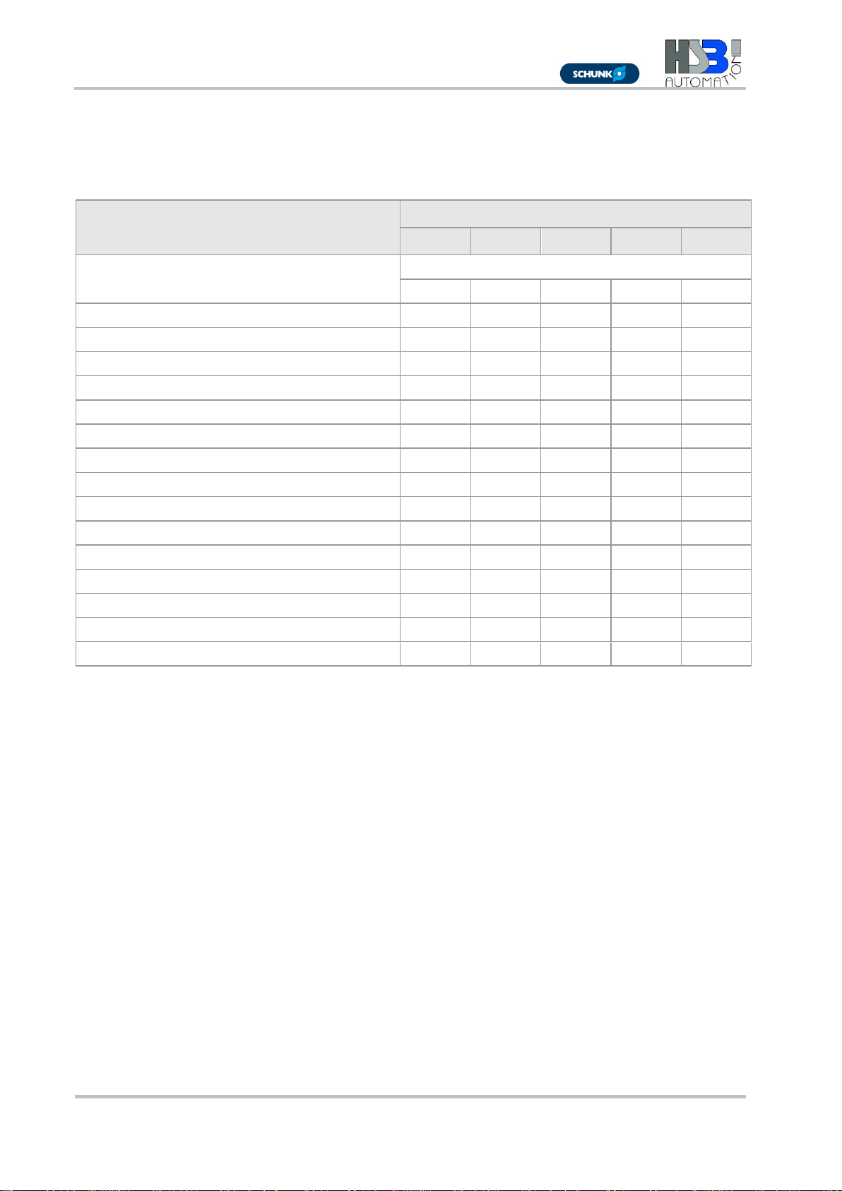
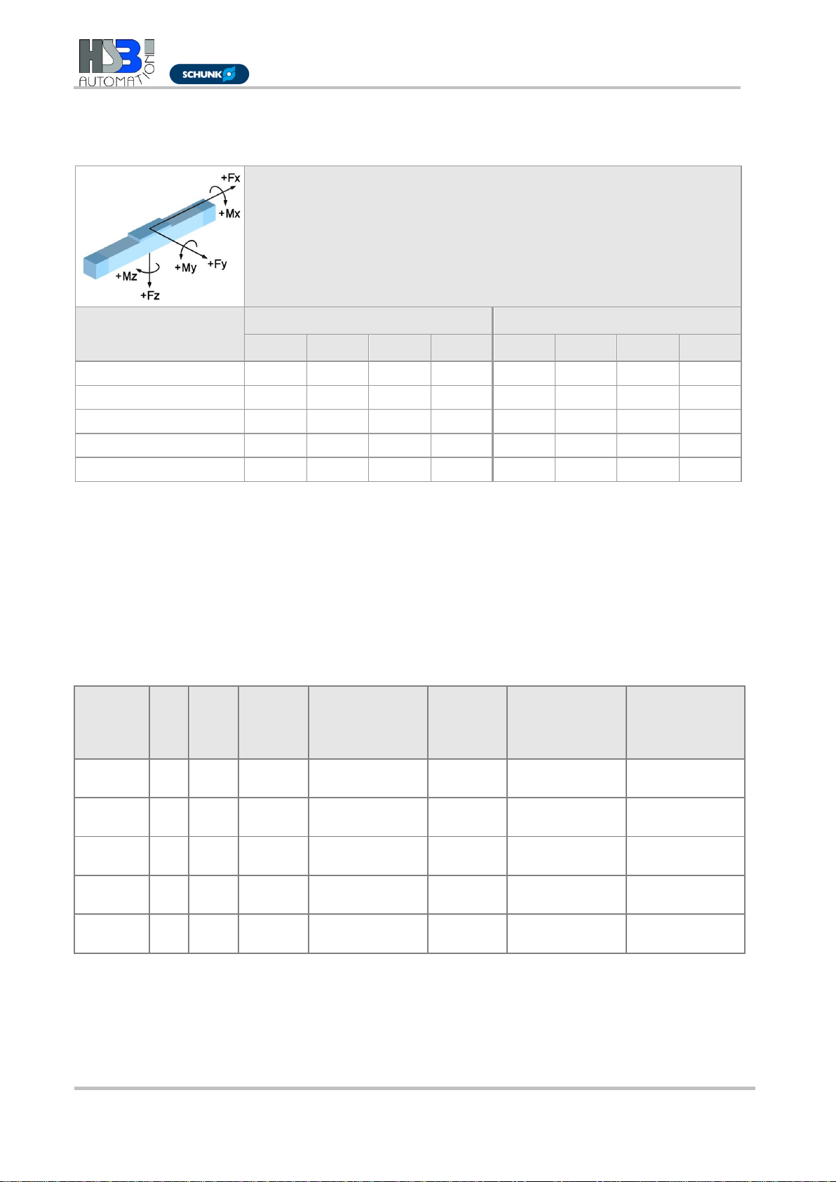
3Technical Data - Standard design ..........................................................................6
4Product description.................................................................................................9
5Transport and Storage ..........................................................................................10
6Assembly and Alignment......................................................................................11
6.1 Screw linear unit into place from underneath........................................................... 11
6.2 Set maximum stroke................................................................................................ 12
6.3 Installing the drive.................................................................................................... 12
6.3.1 Installing the motor...................................................................................12
7Commissioning......................................................................................................14
8Operation................................................................................................................15
9Decommissioning..................................................................................................15
10 Maintenance...........................................................................................................16
10.1 Lubrication............................................................................................................... 16
10.2 Replacing the toothed belt....................................................................................... 19

Safety
22018-06-11 FM 169 A&M Instr. for Gamma type Z..D Rev.01
distributed by
1 Safety
These Operating Instructions are an important part of the machine and
must always be kept within reach.
They must be passed on together with the machine to any third party.
It is important that you contact the manufacturer should there be any
part of these instructions that you do not clearly understand.
1.1 Symbols used
In these Operating Instructions, the following warning symbols and
other symbols are used:
Indicates immediate danger.
Failure to comply with this instruction may result in death or serious
injury.
Indicates a danger carrying a medium to high risk.
Failure to comply with this instruction may result in death or serious
injury.
Indicates a danger carrying low risk.
Failure to comply with this instruction may result in slight injury or
material damage.
Note
Includes tips for the operation and optimum use of the machine.
1.2 Intended use
The linear unit is solely intended for the purpose of manipulating,
positioning, transporting, palletising, loading, unloading, clamping,
synchronising, tensioning, testing, measuring, handling and pressing
of component parts or tools.
Please take note of the principal fields of application of the linear unit
(see Section 4 and Section 3).
In order to guarantee compliance with the law concerning the
electromagnetic compatibility of devices (EMC directive), the linear unit
may only be used for industrial applications (in accordance with
EN 61000-6-1).
Utilisation of the machine for any other purpose would constitute
inappropriate use. The manufacturer accepts no liability for any
damages resulting from such use. The risk is borne solely by the user.

Safety
FM 169 A&M Instr. for Gamma type Z..D Rev.01 2018-06-11 3
distributed by
1.3 General safety
Date of
commissioning
The linear unit may be operated only when the machine or installation
into which it has been built is found to comply with the following
guidelines, laws, regulations and standards:
the relevant accident prevention regulations,
the generally recognised safety guidelines,
EU directives,
standards regarding the electromagnetic compatibility of devices
or machinery,
other applicable standards,
country-specific regulations.
Safe operation
For safe operation, please take into account the following
documentation:
these Operating Instructions for the linear unit, in particular the
Technical Specifications
the Operating Instructions for the entire installation
1.4 Use in potentially explosive areas
The linear units are not suitable for use in potentially explosive
atmospheres.
1.5 Technical condition of the linear unit
State of the art
The unit is state-of-the-art and complies with the applicable regulations.
The unit complies with the following EU machinery directive,
harmonised standards, European standards and relevant national
standards:
EC Machinery Directive 2006/42/EC
EN ISO 12 100:2011-03: Safety of Machinery, General Design
Principles, Risk Assessment and Reduction
EN ISO 13850:2008-09: Safety of Machinery, Emergency
Equipment
DIN EN 60 204-1:2006: Electrical Equipment for Industrial
Machinery
2004/108/EC: EMC Directive
Electromagnetic Compatibility Act: Law on the electromagnetic
compatibility of equipment from 26.02.2008 (BGBI I/Federal Law
Gazette P. 220)

Safety
42018-06-11 FM 169 A&M Instr. for Gamma type Z..D Rev.01
distributed by
1.6 Changes to the linear unit
Rebuilding and
modifying
There are to be no changes, either structural or safety-related, carried
out on the linear unit without the prior written agreement of HRB. We
accept no liability for any unauthorised changes carried out on the unit.
The operator may only carry out the maintenance and repair work
specified in these Operating Instructions. Any further work involving the
replacement of wearing or spare parts may only be carried out following
consultation with our service technicians and by the service technicians
themselves or by HRB.
Never remove or decommission any safety or protection devices.
Follow the assembly instructions supplied by the manufacturer when
using special attachments.
1.7 Requirements for personnel
The linear unit is manufactured using state-of-the-art technology and in
compliance with the recognised safety standards. However, there are
still risks associated with its use. Therefore, only qualified and trained
personnel are permitted to assemble and operate the unit.
Any person involved in the assembly, operation, maintenance, repair or
disassembly of a linear unit must have read and understood these
instructions, in particular the first section entitled "Safety".
Any work involving live parts may only be carried out by trained
electricians. This work involves, for example:
installation of safety limit switches,
attachment of a drive,
checking the direction of the drive rotation.

Warranty
FM 169 A&M Instr. for Gamma type Z..D Rev.01 2018-06-11 5
distributed by
1.8 Responsibilities of the operator
Instruction of
personnel
In accordance with the EU directive 89/655/EEC Art. 6(1) and 7 on the
safe use of work equipment , as well as the EU basic directive
89/391/EEC Art. 1(1) and Art. 6(1), the operator is obliged to provide
any person involved in the assembly, operation, maintenance, repair
or disassembly of the linear unit with instruction and, in particular,
safety-related instruction.
We recommend that the operator acknowledges in writing that the
employees have received the appropriate instruction.
Checking the
unit
The operator is obliged, in accordance with the EU directive
89/655/ECC Art. 4a on the safe use of work equipment, to check the
machine before commissioning, after repair work is carried out and
after any malfunction occurs.
Preservation of
labels
The operator must ensure that any lettering, information signs or labels
are fully legible (in particular the serial number) and always observed.
Any damaged or illegible information signs and labels must be
replaced.
2 Warranty
The warranty conditions are specified in the sales documents (delivery
and payment conditions). The warranty claim expires if:
the unit has not been used in accordance with its intended use,
these Operating Instructions have not been adhered to,
the unit has been modified without prior authorisation from the
manufacturer,
screws sealed using locking paint have been opened.
The manufacturer is only liable if genuine spare parts have been used
during any maintenance or repair work carried out on the unit.

Technical Data - Standard design
62018-06-11 FM 169 A&M Instr. for Gamma type Z..D Rev.01
distributed by
3 Technical Data - Standard design
Gamma ZSSD Linear Unit
Unit sizes
90
120
160
220
280
Drive element
Toothed belt
16AT10
25ATL10
32AT10
40AT10
50ATL10
Moment of inertia [kgm²]
2.20 x 10⁻³
3.85 x 10⁻³
8.70 x 10⁻³
1.55 x 10⁻²
0.12
Stroke per revolution [mm]
200
200
210
240
300
Max. speed [m/s]
5
5
5
5
5
Max. acceleration [m/s2]
60
60
60
60
60
Idle torque [Nm]
2.90
3.00
4.00
5.25
11.00
Maximum stroke (standard) [mm]
7560
7638
7240
11200
8940
Length of standard sliding carriage [mm]
140
150
300
320
400
Repeat accuracy [mm]
±0,08
±0,08
±0,08
±0,08
±0,08
Operating temperature [°C] (Continuous operation)
0 ... 80
0 ... 80
0 ... 80
0 ... 80
0 ... 80
Geometrical moment of inertia IY[mm4]
1373211
4636416
9556948
22915643
52207330
Geometrical moment of inertia IZ[mm4]
2297416
6696292
18711836
53513785
131653724
Weight (without stroke) [kg]
11.50
19.40
39.80
57.50
135.00
Weight (per 100 mm stroke) [kg]
0.96
1.90
2.50
3.60
5.50
Weightofstandardslidingcarriage[kg]
1.90
3.40
7.00
9.30
18.,00
Max. noise emission [dB A] 1)
75
75
75
75
75
1) The value changes when assembled with other parts of the installation

Technical Data - Standard design
FM 169 A&M Instr. for Gamma type Z..D Rev.01 2018-06-11 7
distributed by
Forces and moments for Gamma linear unit with toothed belt drive
Type designation
Dynamic forces [Nm]
Dynamic moments [Nm]
FX
FY
FZ
-FZ
MX
MY
MZ
Midle
Gamma 90-ZSSD
1150
2500
3000
3000
500
800
700
2.90
Gamma 120-ZSSD
1800
6000
8000
8000
1200
1300
1100
3.00
Gamma 160-ZSSD
2200
10000
16000
16000
1800
5000
4000
4.00
Gamma 220-ZSSD
2800
12000
20000
20000
2500
8000
6500
5.25
Gamma 280-ZSSD
4000
20000
30000
30000
4000
15000
12000
11.00
Midle = Idle torque ±30%
The specified forces and moments are the respective maximum values for the single
load. The individual values must be reduced for a mixed load or the occurrence of
several moments or forces at the same time. If in doubt, please contact Technical
Support.
Dynamic load ratings for the Gamma ZSSD linear unit
(THK and Rex = Rexroth)
Unit size
Size
No. of
rails
No. of
carriages
Load rating per
carriage
Cdyn [N]
THK / Rex
Pretensioni
ng FV
[N]
THK / Rex
Guiding distance
in direction x (lx1)
[mm]
Guiding distance
in direction y
(ly) [mm]
Gamma
90-ZSSD
15
2
4
11271 / 9860
564 / 620
75
73
Gamma
120-ZSSD
20
2
4
17700 / 23400
885 / 1500
80
90
Gamma
160-ZSSD
25
2
4
25160 / 28600
1258 / 1820
208
120
Gamma
220-ZSSD
25L
2
4
29208 / 37300
1460 / 2430
210
180
Gamma
280-ZSSD
35
2
4
49448 / 51800
2472 / 3350
275
236
The load rating and pretensioning values refer to the standard linear guide system

Technical Data - Standard design
82018-06-11 FM 169 A&M Instr. for Gamma type Z..D Rev.01
distributed by
Tightening torques [Nm] for fastening screws
Fastening screws
M4
M5
M6
M8
M10
The values given are standard values.
The values must be correspondingly
adapted for shorter screw-in depths.
DIN912/ISO4762-8.8
2.7
5.4
9.0
22.0
43.0
DIN912/ISO4762-10.9
3.0
5.7
9.0
22.0
43.0
DIN912/ISO4762-12.9
3.0
5.7
9.0
22.0
43.0
Tightening torques [Nm] for coupling with clamping hub
Size
14
19
24
28
38
Coupling diameter [mm]
30
40
55
65
80
Screw size
M3
M6
M6
M8
M8
Tightening torque [Nm]
1.34
10.50
10.50
25.00
25.00
Tightening torques [Nm] for coupling with clamping hub
Size
14
19
24
28
38
Coupling diameter [mm]
30
40
55
65
80
Screw size
M3
M4
M5
M5
M6
Tightening torque [Nm]
1.34
2.90
6.00
6.00
10.00

Product description
FM 169 A&M Instr. for Gamma type Z..D Rev.01 2018-06-11 9
distributed by
4 Product description
Rail guide elements
Legend
1
Bearing housing
4
Guide rail
2
Carriages
5
Guide carriage
3
Toothed belt
6
Base profile
Figure 1: Guide elements for Gamma ZSSD linear unit
A mechanical linear unit converts rotary motion into linear motion and
thus facilitates fast, safe and accurate movement of loads from one
position to another. It consists of a basic aluminium profile, a moveable
carriage which is supported by a guide element (linear guide system)
and a drive element (rack-and-pinion or toothed belt drive).
Depending on the design, the carriage can absorb forces and moments
in all directions and is non-positively connected to the guide and drive
element via the slide plate.
The basic profile is self-supporting up to a certain length and fitted with
grooves to keep it in place.
The operating area can be flexibly arranged. Several Gamma linear
units can be configured to cover a large area (2 axes) or in a spatial
arrangement (3 axes).
A plate can be used to connect driven linear units to non-driven linear
units of the same type, for example in order to be able to take on large
loads.

Transport and Storage
10 2018-06-11 FM 169 A&M Instr. for Gamma type Z..D Rev.01
distributed by
5 Transport and Storage
The mechanical linear unit is a precision instrument. Any heavy impact
to this instrument may damage the mechanics and impair its
functionality.
Risk of damage by heavy impact or bending!
Only transport an assembled linear unit using transport locks.
In order to avoid any damage to the linear unit when storing or
transporting it, the following measures must be taken in order to protect
it from jolting or slipping:
Transport the unit in a sufficiently large container
Use cushioned packaging
The weight values for the units are listed in section 3.
The units must be protected against:
Dirt,
Corrosion,
Water
and an aggressive atmosphere.

Assembly and Alignment
FM 169 A&M Instr. for Gamma type Z..D Rev.01 2018-06-11 11
distributed by
6 Assembly and Alignment
The linear unit can be mounted as follows:
With screws in the sliding blocks
With screws in the factory-fitted threaded rails
Only mount the linear unit onto a flat surface. Standard parallelism
<0.2 mm/1000 mm.
Mounting the linear unit using the threaded rails is recommended
for the following situations:
For highly dynamic applications
For just 2 fixing points on the linear unit
6.1 Screw linear unit into place from underneath
Figure 2: Sliding blocks (1) in the groove on the underside of the basic profile
Secure the linear unit using fastening screws from below using the
sliding blocks or the threaded rails in the basic aluminium profile
(Figure 2).
Proceed as follows:
1. Align the linear unit.
2. Align the sliding blocks (1) / threaded rails.
3. Screw the linear unit into place
(for tightening torques refer to section 3).

Assembly and Alignment
12 2018-06-11 FM 169 A&M Instr. for Gamma type Z..D Rev.01
distributed by
6.2 Set maximum stroke
Risk of serious injury from overturning transport devices.
Should the carriage come to a stop beyond the safety area, the
transport devices mounted to this can break off or overturn. This can
damage the linear unit.
Please take note of the specified safety area when setting up the unit
and set the limit switch correspondingly.
Electric switches may only be connected by a qualified electrician.
Allow for a sufficient braking distance to ensure that there is enough
time to slow down the carriage in the case of an emergency stop.
6.3 Installing the drive
6.3.1 Installing the motor
Legend
1
Coupling half 1
4
Motor mounting
2
Coupling collar
D
Diameter at motor mounting
3
Coupling half 2
Figure 3 Motor mounting with motor coupling at drive journal

Assembly and Alignment
FM 169 A&M Instr. for Gamma type Z..D Rev.01 2018-06-11 13
distributed by
Proceed as follows:
1. Place the motor and the coupling elements in the mounting position
alongside the linear unit.
2. Check the direction of rotation of the motor. If necessary, adjust the
direction of rotation.
3. If the coupling diameter is smaller than the D measurement at the
motor mounting (4), first mount the coupling half 1 (1) (bore flush
with the drive shaft) and then the motor mounting (4)
(Figure 3).
If the coupling diameter is larger than the D measurement at the
motor mounting (4), first mount the motor mounting (4) and then the
coupling half 1 (1) (bore flush with the drive shaft). Tighten the
coupling clamping screw using the mounting bore at the motor
mounting (4).
4. If necessary, push the coupling collar (2) onto the coupling.
5. Fix the coupling half 2 (3) to the motor journal.
6. Attach the motor to the motor mounting.

Commissioning
14 2018-06-11 FM 169 A&M Instr. for Gamma type Z..D Rev.01
distributed by
7 Commissioning
Risk of injury or damage to other installation parts
due to quick linear movements of the transport devices
due to centrifugal load.
Only authorised personnel are permitted to commission the linear unit.
Risk of crushing due to incorrect direction of movement of the transport
devices.
Should the direction of rotation of the drive (motor or gear) and the
sliding carriage drive (spindle or toothed belt) not correspond, the
mounted transport devices may travel in the wrong direction. Around all
rotating parts (e.g. GX shaft) there is a risk of being pulled in, and of
clothing or body parts being caught up and trapped. There is also a risk
of crushing around the moving carriage and the rack-and-pinion drive.
These hazards can be countered by installing effective safety
mechanisms that comply with the current standards and are state-of-
the-art. These are not supplied with the linear unit and must be installed
by the manufacturer of the overall installation.
Only qualified electricians are permitted to carry out any work on the
electrical installation or check the direction of rotation.
Checking the
unit before
commissioning
Before commissioning, the following must be checked:
whether the holding devices used are consistent with the mass and
acceleration information provided by the manufacturer,
whether the machine or installation in which the linear unit is
installed corresponds to the provisions set out by the machinery
directive, the harmonised standards, the European or national
standards,
whether the linear unit is correctly mounted
whether the inductive and/or mechanical limit switch is correctly
connected and functioning properly.
whether the direction of rotation of the motor shaft and, if
applicable, the intermediary gear corresponds to the direction of
rotation of the spindle or the toothed belt.
If there are faults detected during this inspection, commissioning is not
permitted.
Test run
In order to avoid any accidents or collisions, the linear unit must be
moved along the stroke several times at a rate slow enough that it can
be stopped immediately in case of an emergency.
The installation can be started up after it has been ensured that there is
no risk of a collision when exceeding the maximum stroke.

Operation
FM 169 A&M Instr. for Gamma type Z..D Rev.01 2018-06-11 15
distributed by
8 Operation
The drive motor can heat up considerably during operation.
In this case, refer to the operating instructions supplied for the drive
motor.
In addition, hazards can occur due to noise, tilting and falling, failure to
observe ergonomic principles, and the surroundings in which the unit is
used.
Various combinations of hazards are also possible.
These items should be analysed by the manufacturer or operator of the
overall installation in a separate risk assessment.
Risk of damage due to harmful environmental influences!
The linear unit may only be operated under environmental conditions
which are permitted by the manufacturer.
Environmental
conditions
The linear unit may only be operated within the permitted temperature
range of 0 –80 °C.
Operating in damp, abrasive conditions may result in foreign objects
entering components in the linear unit. In order to prevent this, the
operator must take the necessary measures to avoid the infiltration of
foreign objects, e.g. folding plates, wash plates.
Required inspection
The linear unit must be occasionally checked during operation to see
that it is functioning correctly.
The personnel responsible must check the linear unit and the
machinery for any visible signs of damage or defects at least once
during each shift.
Should there be any changes observed which may compromise safety,
it must be switched off immediately.
Emergency stop
The maximum permissible loads must not be exceeded even in an
emergency stop situation.
9 Decommissioning
Risk of injury or damage to other installation parts due to falling parts.
Only authorised personnel are permitted to disassemble the linear unit.
1. Separate the machine/installation from the mains supply.
2. Disassemble the drive from the linear unit.
3. Unscrew the linear unit from the machine/installation.

Maintenance
16 2018-06-11 FM 169 A&M Instr. for Gamma type Z..D Rev.01
distributed by
10 Maintenance
Around all rotating parts (e.g. GX shaft) there is a risk of being pulled
in, and of clothing or body parts being caught up and trapped. There is
also a risk of crushing around the moving carriage and the rack-and-
pinion drive.
For this reason, lubrication of the linear unit may only be carried out
while it is moving slowly (max. 0.025 m/s), and for any cleaning work
the linear unit drive must be shut down and secured against being
restarted.
All mounted ball bearings are sealed and maintenance-free.
Remove excessive dust and dirt from the cover band and other
parts of the linear unit regularly.
10.1 Lubrication
Influencing factors
The following influencing factors are important for an accurate
regulation of lubrication intervals:
Load
Speed
Motion sequence
Operating temperature
Degree of contamination
Short lubrication
intervals
Short lubrication intervals are required for:
operation under the influence of dust and dampness
a heavy load
high speed (up to Vmax)
short strokes
Initial lubrication
After commissioning, carry out the initial lubrication. The basic
lubrication has already been carried out by the manufacturer.
Refer to the lubrication regulations on the following pages.

Maintenance
FM 169 A&M Instr. for Gamma type Z..D Rev.01 2018-06-11 17
distributed by
Lubrication points on
linear units size 90
and 120
Figure 4: Lubrication points (1) or (2) on carriage
The lubrication points are located on the front faces (1) or on the sides
(2) of the guide carriages (4 x per carriage). For size 120, the side
lubrication point (2) is preferred as the two carriages can run very
closely together and therefore a collision between the front face
lubrication connections can occur.
The lubrication plan outlined below applies for the lubrication points.
Size 160 to 280
Figure 5: Lubrication points (1) on the carriage
The lubrication points (1) are on the two long sides of the carriage and
each supply two guide carriages (meaning it is only possible to
relubricate from one side).
The lubrication plan outlined below applies for the lubrication points.
Lubrication method
Lubrication should take place as far as possible while in motion so that
the grease is distributed and no pressure builds up.

Maintenance
18 2018-06-11 FM 169 A&M Instr. for Gamma type Z..D Rev.01
distributed by
Lubrication plan for lubrication point F
Guide carriage size
Lubrication interval
Amount of
grease [cm³] per
guide carriage
Type of grease
15 with ball chain
approx. 5,000 km*
approx. 0.4
Grease in accordance with
DIN51825-KPE1R-20, e.g.
Klüberplex BE 31-102
Please take note of
the instructions
provided by the
lubricant manufacturer
should a different type
of grease be used!
Grease with a solid
lubricant component
(e.g. graphite, MoS2)
is not to be used!
20 with ball chain
approx. 0.6
25(L) with ball chain
approx. 1.2
35 with ball chain
approx. 1.7
15 without ball chain
approx. 2,000 km*
approx. 0.8
20 without ball chain
approx. 1.4
25(L) without ball chain
approx. 2.8
35 without ball chain
approx. 4.4
*Or at least twice a year. The lubrication interval depends on the environmental conditions and the load. Relubrication
“in motion”!
Figure 6: Relubrication intervals for the linear guide system with ball chain
Degree of
contamination
Load
high
medium
low
heavy contamination
(swarf, coolant)
medium contamination
slight contamination
(assembly hall)
no contamination
(lab, measuring rooms)
This manual suits for next models
4
Table of contents
Other HSB Industrial Equipment manuals
Popular Industrial Equipment manuals by other brands

Enerpac
Enerpac Pull-pac BRP106C instruction sheet

Venmar
Venmar K7 ERV User's and installer's manual

GRUNDFOS ALLDOS
GRUNDFOS ALLDOS Oxiperm C 164 Series Operation and service manual

Graco
Graco 25C528 Instructions - parts

Magnaflux
Magnaflux D-2000 Series Operation manual

Nexen
Nexen AIR CHAMP MWHS user manual