engelmann SensoStar 2C Ultrasonic User manual

Engelmann
The heat meter specialists
®
Engelmann Sensor GmbH, Rudolf-Diesel-Straße 24-28 , 69168 Wiesloch-Baiertal, Germany
Phone.: +49 (0)6222-9800-217 , Fax: +49 (0)6222-9800-50, E-Mail: [email protected], www.engelmann.de
Article-No. 1080700010 - 2011-04-01 Page 1
Calculator with Ultrasonic
DE-09-MI004-PTB018 / 22.72/09.01
Installation and Operating Instructions
4.1 Safety instructions
– Look out for sharp edges (pipes, flanges).
– Installation and deinstallation should only be carried out by
qualified technical personnel.
– Mounting and dismounting may only be carried out without
pressure in the heating or cooling system.
– After installation a hydraulic pressure test should be carried out
using cold water to check for leaks.
– For safe operation, the instrument must be used only under the
stated operating conditions (see section 15: Technical Data).
In addition, the guarantee only applies if the allowed operating
conditions have been adhered to.
– The security seals may not be damaged, otherwise the guaran-
tee is no longer valid.
– Protection against lightning is not guaranteed; lightning protec-
tion must be implemented at the installation site.
4 Mounting the Flow Sensor
1 Application and Function
The
SENSOSTAR®2C US
Ultrasonic Meter is designed for the
measurement of heat and cooling energy. The connected flow sen-
sor must be installed in the return flow. Optionally, the meter can be
set in the factory to measure flow volume in the forward flow (state
when ordering – not for cooling meters!).
The instrument has an optical interface for read-out and parameteri-
zation. Optionally, the instrument can be equipped at the factory with
an M-bus interface, up to two pulse outputs (for energy and volume)
or alternatively with two pulse inputs. It is also possible to power the
instrument using a power pack (not available in combination with
M-bus power supply.)
4.2 General information on the flow sensor
– Be careful not to pick up the flow sensor on the plastic housing.
Always pick up and carry the sensor on the threaded or flanged
connections.
– All cables must be laid at a minimum distance of 20 cm to high-
voltage current cables.
– If more than one sensor is being installed in a unit, care must
be taken to be sure that all the meters have the same installati-
on conditions.
– Overpressure must be applied in order to avoid cavitation in the
complete measurement range; this means at least 1 bar up to
qp and approx. 3 bar at overload qs (specifications for approx.
80°C).
– The flow sensor left the factory in conformance with all ap-
plicable safety regulations. Calibration, maintenance, repairs
and the exchange of parts may only be carried out by qualified
technical personnel who are familiar with the dangers involved.
Further technical support can be provided by the manufacturer
upon request. Verification seals on the flow sensor may not be
damaged or removed – otherwise the guarantee and verifica-
tion of the instrument no longer apply!
4.3 Technical data of the flow sensor
– Environmental class A (EN1434), for indoor installation
– Mechanical class M1*)
– Electromagnetic class E1*)
*) as per Measurement Instrument Directive 2004/22/EU
2 Scope of Delivery
• Calculator
SENSOSTAR®2C US
• Installation kit: 1 O-ring; 5 selflock seals + 5 sealing wires;
2 screws + 2 dowels for direct screw mounting (if this
technique is used - see section 9.3)
• Installation and Operating Instructions
• 2 gaskets for the flow sensor
3General Information
All details and specifications listed in instrument data sheet or in
these installation and operating instructions must be adhered to:
• The valid statutory provisions and standards for the application of
instrument for the measurement of heat energy are: EN1434 parts
1+6 and the Directive 2004/22/EC with annexes I and MI-004.
• The instrument may only be installed or exchanged by qualified
and authorized technical personnel.
• The regulations for electrical installations must be adhered to
• The applicable verification regulations and periods for the country
in which the instrument is to be installed must be observed.
• The instrument left the factory in conformance with all applicable
safety regulations.
• The instrument must be stored and transported frost-free. The
temperature during storage or transport may not fall below 1°C.
The relative humidity during storage and transport may not be
more than 80%.
• The instrument identification and the seals required for verification
of the instrument must not be damaged or removed – otherwise
the guarantee and verification of the instrument no longer apply!
• To clean the instrument (only if necessary) use a slightly moist
(not dripping wet!) cloth.
• To protect against damage and dirt the instrument should only be
removed from the packaging directly before installation.
• All electrical connections of the instrument must be laid at a
minimum distance of 50 cm to sources of electromagnetic
interference (switches, controllers, pumps, etc.)
• All instrument connections must be laid at a minimum distance
of 10 cm to other current-carrying wires.

Engelmann Sensor GmbH, Rudolf-Diesel-Straße 24-28 , 69168 Wiesloch-Baiertal, Germany
Phone.: +49 (0)6222-9800-217 , Fax: +49 (0)6222-9800-50, E-Mail: [email protected], www.engelmann.de
Article-No. 1080700010 - 2011-04-01
Engelmann
The heat meter specialists
®
Page 2
Straight pipe section none required
Accuracy class 1:100 or 1:50
Temperature range
• recommended for heat
• recommended for cooling
5 0C to 130 0C *)
10 0C to 130 0C **)
5 0C to 50 0C
*) national approvals may vary
**) Short model 150 mm only from 20 0C to 130 0C
Max. medium temperature 150 0C for 2000 h
Protection rating flow sensor
IP 54 for heat or
IP 65 for cooling (optional for
heat meter)
Maximum overload 2.8 x qp
Nominal pressure PN 16, PN 25
Electronics:
Storage temperature -20 0C to 60 0C
Ambient temperature 5 0C to 55 0C
Ambient humidity < 93 % rel. humidity
Flow sensors:
(Please note the specifications on the sensor itself!)
Flow sensor
Pulse output type
electromechanical switch (reed contact)
class OA as per EN1434-2:2007
passive electronic current sink (open
collector) class OC as per EN1434-2:2007
Installation point
standard in return flow
optional
in forward flow (only for heat
meter), calculator must be set in
factory
Mounting position
Heat meter any
Mounting position
Cooling meter
see section 6: Installation for Cooling Applica-
tions
4.4 Small flow sensors
Nominal flow
qp
Installation length
Connection
Max. flow qs
Min. flow qi
Activation limit
(variable)
Pressure drop
at qs
Kv-Durchfluss
bei q1 bar
Kv-Flow at
q100 mbar
Weight
m3/h mm G / DN m3/h l/h l/h mbar m3/h m3/h kg
110 G ³/41
G 1 1,5
DN 20 125 1,7 3
110 G ³/4150 3,9 1
DN 20 3
130
DN 20 195 5,7 3
G 1 1/4 3
DN 25 5
G 1 1/4 3
DN 25 5
6 150 G 1 1/4 12 60 24 240 12 4,5 3
200
100 32 10 4
DN 40 165 25 7,8 7
200 115 44 14 5
270 100 47 15 8
25 300 DN 65 50 250 100 105 77 24,4 11
40 300 DN 80 80 400 160 160 100 31,6 13
60 360 DN 100 120 600 240 115 177 56 22
60
2,6
300
G 2 8,8
40
130 28
15 DN 50 30 150
190
10 20 100
14 60 14 4,53,5 260 7 35
25 10
1,51,2
160 3,8
1,5
24 180 14
2,5 G 1
6260 1260
5
4,5
200 5,6 1,8
1,5 3 15 6
130
190
G 1
0,6 190 1,2 6 2,4 150 1,5 0,5

Engelmann
The heat meter specialists
®
Engelmann Sensor GmbH, Rudolf-Diesel-Straße 24-28 , 69168 Wiesloch-Baiertal, Germany
Phone.: +49 (0)6222-9800-217 , Fax: +49 (0)6222-9800-50, E-Mail: [email protected], www.engelmann.de
Article-No. 1080700010 - 2011-04-01 Page 3
190
22,6
G 1
190
22,6
G 1
190
18 Ø 75
Ø 58
4.5 Large sensors with threaded connection
4.6 Large sensors with flange connection
qpm3/h PN bar a b c d
3,5 16 260 51 G 1 1/4 B
6 16 260 51 G 1 1/4 B
6 16 150*) 22 G 1 1/4 B
10 16 200 48 G 2 B
10 16 300 48 G 2 B
*) For the short models with length 150 mm, the temperature
range for the medium lies between 20 0C and 130 0C.
4.7 Premium Flow Sensors
Please note that the normal flow sensors may not be used
with salt water.
Upon request, we can provide salt-water resistant versions
of the flow sensors.
q
p
m³/h
PN
bar DN a b Øc Ød Øe
No. of
holes fg
3,5 25 25 260 51 115 85 14 4 68 18
6 25 25 260 51 115 85 14 4 68 18
10 25 40 300 48 150 110 18 4 88 18
15 25 50 270 46 165 125 18 4 102 20
25 25 65 300 52 185 145 18 8 122 22
40 25 80 300 56 200 160 18 8 138 24
60 16 100 360 68 235 180 18 8 158 24
60 25 100 360 68 235 190 22 8 158 24

Engelmann Sensor GmbH, Rudolf-Diesel-Straße 24-28 , 69168 Wiesloch-Baiertal, Germany
Phone.: +49 (0)6222-9800-217 , Fax: +49 (0)6222-9800-50, E-Mail: [email protected], www.engelmann.de
Article-No. 1080700010 - 2011-04-01
Engelmann
The heat meter specialists
®
Page 4
7 Starting Up
Open close-off valves. Check the heating system for leaks and
vent thoroughly. After 100 seconds at the latest the flow sensor
will begin to operate.
When the response threshold has been exceeded and the flow
is positive, volume pulses will be generated as determined by
the instrument parameterization.
Check the measured flow values on the connected calculator
for plausibility. Vent the system until the flow display on the
connected calculator is stable. Then affix the user seals on the
connections.
8 Important Notes
– Regulations for the application of meters are to be obser-
ved, see Standard EN 1434, part 6! In particular, cavitation
must be avoided.
– When installing the flow sensor, make sure to protect
against overflow and dripping water
– All technical data specified in the flow sensor data sheet
and instructions must be adhered to.
– The instrument identification and the seals required for
verification of the flow sensor must not be damaged or
removed – otherwise the guarantee and verification of the
instrument no longer apply!
– Transport of the flow sensor is only permissible in the origi-
nal packaging.
.
Permissible mounting positions for cooling applications
30
o
C
80
o
C
10 DN
Black housing of transducers
5 Integration in the Heating System
Please inspect and check all dimensions to be sure that there
is sufficient space in the intended location for installation of the
flow sensor.
No minimum straight pipe sections are required upstream or
downstream for the flow sensor.
If the flow sensor is being installed in the common return flow
of two heat systems, e.g. heating and hot water, the mounting
location must be sufficiently separated from the T-piece, that
is, at least 10 x DN from the T-piece, so that the different water
temperatures are well-mixed before reaching the sensor.
Mixture of different return flow temperatures
Flush the system thoroughly before installing the flow sensor.
Following the instructions in the illustrations below, mount the
flow sensor horizontally or vertically between two close-off
valves, making sure the arrow on the sensor corresponds to the
actual direction of flow.
Connection pieces are to be sealed against manipulation.
Mounting considerations
Point 1: Avoid air pockets
Point 2: Install any valves or controllers downstream from
the flow sensor.
6 Installation for Cooling Applications
When mounting the flow sensor for cooling applications make
sure that the transducers (black housing) are to the side of, or
under, the measuring tube (to prevent accumulation of conden-
sation water). The flow sensor must always be mounted in the
return flow. The calculator should be mounted on the wall, for
example.
Attention must be paid that the cables connected to the calcu-
lator are laid such that condensation water cannot run along
them and into the calculator. Cable loops should hang under-
neath.

Engelmann
The heat meter specialists
®
Engelmann Sensor GmbH, Rudolf-Diesel-Straße 24-28 , 69168 Wiesloch-Baiertal, Germany
Phone.: +49 (0)6222-9800-217 , Fax: +49 (0)6222-9800-50, E-Mail: [email protected], www.engelmann.de
Article-No. 1080700010 - 2011-04-01 Page 5
9.2 With commonly available mounting rail
9.3 Direct screw mounting
10 Connection of Components
Important: First mount the temperature sensors and then connect
the flow meter to the calculator. This way unnecessary error mes-
sages can be avoided.
At delivery, the display shows ‘ERR 03’ until temperature sensors
have been attached. This message disappears as soon as tempe-
rature sensors have been connected and the first measurement is
carried out (every 30 seconds for standard instruments).
Recognition of switched temperature sensors is only activated for
meters which are purely heat meters or cooling meters.
Recognition of switched sensors is not possible for dual-purpose
heat / cooling meters.
The
SENSOSTAR®2C US
connections have been designed to
meet the valid standard EN1434-2. All terminal strips have been
labeled according to this standard.
The terminal strips are located under the cover of the calculator
housing.
10.1 Temperature sensor connection
Before connecting the temperature sensors to the calculator ple-
ase check the following points:
– The temperature sensors (up to DN 100) must installed
against the flow direction.
– The temperature sensor with the red identification must
always be installed in the forward flow.
– The temperature sensor with the blue identification must
always be installed in the return flow.
– The temperature sensors are not to be installed within the
influence of other sources of heat.
– Do not kink, lengthen or shorten the cables.
– Cables that are too long should not be rolled up tightly into an
‘air-core coil’. The cables should either be laid out unordered,
or rolled up loosely into a wide coil which can be turned and
tied into an ‘8’.
Mounting
– Loosen two cable glands and glide them over the sensor
cables. Remove the two blind plugs from the cable gland
openings.
– Feed the temperature sensor cables through the appropriate
openings of the cable glands into the terminal box.
– Clamp the wires as shown in the illustrations. Make sure the
temperature sensor connection is correct:
Sensor with red identification →forward flow
Sensor with blue identification →return flow
9 Wall Mounting of Calculator
The housing cover can be opened by pulling the two snap-fit
hooks at the base of the calculator (between the cable glands)
towards you.
After mounting, all calculators must be sealed against manipula-
tion at the holes provided on the housing cover (see section 9.1)
using the seals and wires included in the delivery (see 2 ′Scope of
Delivery′).
Before mounting, check to make sure that the cable lengths of the
instruments to be connected are correct for the individual installa-
tion situation.
For existing mounting positions an optional adapter panel
- meeting EN1434-2:2007 (D) specifications – is available which
makes it possible for the wall-mounting support to be mounted
using standardized drill holes. The center to center drill hole
separation for the wall-mounting unit (see 9.1) and direct screw
mounting (see 9.3) is 119 mm.
9.1 With wall-mounting support
holes for
sealing
holes for
sealing

Engelmann Sensor GmbH, Rudolf-Diesel-Straße 24-28 , 69168 Wiesloch-Baiertal, Germany
Phone.: +49 (0)6222-9800-217 , Fax: +49 (0)6222-9800-50, E-Mail: [email protected], www.engelmann.de
Article-No. 1080700010 - 2011-04-01
Engelmann
The heat meter specialists
®
Page 6
– Check that the connections are tight.
– Screw the cable glands tight by hand.
Connection for 4-wire technique
Connection for 2-wire technique
10.2 Connection of optional interfaces
• The following are options that the calculator can be equip-
ped with at the factory (state when ordering) and will vary
depending on the individual calculator.
• Feed the cable to be connected (cable diameter Ø 3.5 to 6.5
mm) through an opening on the bottom edge of the calcula-
tor housing into the space containing the terminal strips.
• The terminal clamps are designed to fit strands with ends
with a cross-section of 0.5 – 1.5 mm2.
• Clamp on the cable according to the following illustrations
that apply depending on the interface.
Depending on the option,
here there are located two
additional pulse inputs (IN)
for further meters or two
pulse outputs (OUT) for
connection to an additional
system.
For connection of meters
with open collectors atten-
tion must be paid to the
polarity.
Polarity is not important for
these connections so the wires
can be clamped arbitrarily.
When the M-bus network is in
operation a triangle will appear
in the lower right corner of the
display.
(Power supply from the M-bus
network is functioning.)
Connection of M-bus
Connection of pulse outputs or inputs
Connection of power pack
It is strongly recom-
mended to use only the
Engelmann Sensor
power pack.
It is imperative to pay
attention to the polarity
Important note: The flow sensor is not powered by the
power pack!
Attention: Please check the unused cable glands to make
sure that the necessary blind plugs are inserted
and then tighten the cable glands by hand.
• Check that the connections are tight.
• The power pack should only be connected to 230V and
checked by authorized technical personnel.
• Check on the display whether a
triangle appears in the lower right
corner, as shown in the illustration.
• Screw the cable gland tight by hand.
• Close the cover of the calculator housing and protect
against unauthorized opening using the delivered
Optional:
For the dual-purpose heat/
cooling meter version, sepa-
rate pulse outputs for heating
energy and cooling energy
are available.

Engelmann
The heat meter specialists
®
Engelmann Sensor GmbH, Rudolf-Diesel-Straße 24-28 , 69168 Wiesloch-Baiertal, Germany
Phone.: +49 (0)6222-9800-217 , Fax: +49 (0)6222-9800-50, E-Mail: [email protected], www.engelmann.de
Article-No. 1080700010 - 2011-04-01 Page 7
11 Calculator Operation
The
SENSOSTAR®2C
calculator has a liquid crystal display with 8 digits and special characters. The values that can be shown
are divided into three display loops.
All data is retrieved using the Engelmann pushbutton next to the display.
To scan all the information in a loop, simply press the pushbutton briefly. To change to the next loop press the pushbutton longer.
Keep the pushbutton pressed until you reach the desired information loop. As soon as the desired loop appears, let go of the push-
button. After one minute of non-use of the pushbutton, the display automatically returns to the main loop.
1. Level / Main Loop
1) Total heat energy / total cooling energy
–standard display-
(alternating display without pressing the
button heat/cooling meters)
2) Segment test, all segments triggered
simul-taneously.
3) Total heat energy / cooling energy at last
billing date alternating with that date. 1)
Flow volume, tariff values, or the values of the
individual pulse counters can be shown if this
has been set.
4) Total volume in m3
5) Current power in kW
6) Current flow in m3/h
7) Current date
8) Error message (alternating binary and
hexadecimal display)
9) Selectable customer-set calculator no.
(secondary address); factory setting is the
serial no.
10)Tariff register1: Values alternating with
tariff register and criteria. 2) 3)
11)Tariff register 2: Values alternating with
tariff register and criteria. 2) 3)
12) Momentary reading of the pulse counter1
alternating with the pulse value.2) 3)
13) Momentary reading of the pulse counter 2
alternating with the pulse value.2) 3)
2. Level / Technician’s Loop
1) Current forward flow temperature in C°
2) Current return flow temperature in C°
3) Temperature difference in C°
4) Days since first verification of calculator
5) Pulse value of calculator
6) M-bus address (primary address)
7) Serial number
8) Software / firmware version
9) return flow or forward flow
Temperature sensor type and mounting
position
10) Set billing date
11), 13), 15) Maximum power value
alternating with date and time of
occurrence.
12), 14), 16) Maximum flow value alternating with
date and time of occurrence.
1) Previous billing date alternating with its values.
Alternatively, the total volume, tariff values, or values of
individual instruments connected to the optional pulse inputs
can be displayed, if so set. 1)
2-16) 15 Monthly values: Dates alternating with their values.
Alternatively, the total volume, tariff values, or the values of
individual pulse counters can be displayed, if so set. 1)
3. Level / Statistics Loop
1) Up to the end of the month the consumption and billing date for that month will be shown as 0.
2) Can be set using the software “Engelmann®Monitor”. A dedicated meter password is necessary. Password available from manufacturer.
3) Note: For invoicing, the total heat energy must be used.

Engelmann Sensor GmbH, Rudolf-Diesel-Straße 24-28 , 69168 Wiesloch-Baiertal, Germany
Phone.: +49 (0)6222-9800-217 , Fax: +49 (0)6222-9800-50, E-Mail: [email protected], www.engelmann.de
Article-No. 1080700010 - 2011-04-01
Engelmann
The heat meter specialists
®
Page 8
12 Calculator Settings
12.1 Pulse inputs 1+2
The optional pulse inputs 1+2 for external meters can be set using
the configuration software Engelmann®Monitor. The settings are the
input pulse value and the units in which the external meter counts.
For invoicing, the meter readings of the instruments connected to
the pulse inputs must be included in the calculation
12.2 Pulse output for energy (OUT1-Energy)
A pulse is sent via the pulse output for energy when the last digit
of the energy display is increased. The pulse value is automatically
determined by the last place of the energy display.
The pulse units are identical to the units of the energy display:
Example 1: Display 12345678 kWh => pulse value for energy pulse
output = 1 kWh / pulse
Example 2: Display 12345,678 MWh => pulse value for energy
pulse output = 0.001 MWh / pulse
Example 3: Display 1234567,8 GJ => pulse value for energy pulse
output = 0.1 GJ / pulse
12.3 Pulse output for volume (OUT2-Volume)
A pulse is sent via the pulse output for volume, when the second-
to-last digit of the volume display is increased.
The pulse value is automatically determined by the second-to-
last place of the volume display. The pulse units are identical to
the units of the volume display.
Example 1: Display 12345,678 m3=> pulse value for volume
pulse output = 0.01 m3/ pulse
Example 2: Display 12345678 l => pulse value for volume pulse
output = 10 l / pulse
Display examples Description of example in tariff register 1
(either the energy or the time can be measured)
0 Not defined (at delivery).
1 The energy (0.683 MWh) in the time period from 18.00 (6 pm) to
6.00 am (the time can be set in 10-min. steps) is being measured.
2 The energy (0.683 MWh) above a power of ≥2.000 kW
3 The energy (0.683 MWh) up to a power ≤2.000 kW
4 The energy (0.683 MWh) above a flow of ≥0.600 m3/h
5 The energy (0.683 MWh) up to a flow ≤0.600 m3/h
6 The time (11 h) above a temperature in the
forward flow of ≥65.00 oC (in steps of 0.01 oC)
7 The time (11 h) up to a temperature in the
forward flow ≤65.00 oC (in steps of 0.01 oC)
8 The time (11 h) above a temperature in the
return flow ≥36.00 oC (in steps of 0.01 oC)
9 The time (11 h) up to a temperatur in the
return flow ≤36.00 oC (in steps of 0.01 oC)
10 The energy (0.683 MWh) above a
temperature difference of ≥10.00 oC (in steps of 0.01 K)
11 The time (11 h) up to a temperature difference
of ≤10,00 oC (in steps of 0,01 K)
12.4 Tariff registers
There are 2 tariff registers, which add up the energy or time, depending on certain criteria. The registers can be individually set using the
Engelmann®Monitor software and can be read via the display or using the read-out software.

Engelmann
The heat meter specialists
®
Engelmann Sensor GmbH, Rudolf-Diesel-Straße 24-28 , 69168 Wiesloch-Baiertal, Germany
Phone.: +49 (0)6222-9800-217 , Fax: +49 (0)6222-9800-50, E-Mail: [email protected], www.engelmann.de
Article-No. 1080700010 - 2011-04-01 Page 9
13 Interfaces and Options
13.1 Optical (infrared) interface
In order to be able to communicate with a
SENSOSTAR®2C
ins-
trument, an optocoupler must be connected to the USB or serial
interface of the PC. The optocoupler (USB or serial interface) and
the Engelmann®Monitor software are available as options.
The optical (infrared) interface is activated by pressing the
Engelmann pushbutton.
If within 60 seconds neither a valid telegram is received now the
pushbutton pressed again, then the interface is deactivated.
13.2 M-bus interface
An M-bus interface is also available as a built-in option for the
SENSOSTAR®2C
(must be stated when ordering). An inst-
rument with an M-bus interface is supplied with power via the
M-bus network (no galvanic separation). The number of read-outs
via the M-bus interface per instrument per day is unlimited.
The valid standards for the M-bus protocol are EN13757-2 and
13757-3 and the M-bus recommendation (Version 4.8 from Nov.
1997) with the standard IEC 870 part 1,2 and 4.
Notes on installation:
• Each end instrument is only protected against high voltage
up to the maximal allowed bus voltage (±50V). Additional
protective measures must be provided by the level converter.
• The installation of an instrument in an M-bus network may
only be carried out by authorized, qualified technical
personnel.
• Attention must be paid to ensure that the cable lengths and
cable cross-sections in the bus network are appropriate for
the baud rate of the end instrument (2400 baud).
• Recommended cable type:
Telephone cable J-Y(ST) Y2 x 2 x 0.8 mm²
SENSOSTAR®2C
instruments with the M-bus option can be
addressed primarily or secondarily.
Both addresses can be set via the optical interface using the
Engelmann®Monitor software. They can also be set using the
display.
The primary address is the M-bus address displayed in the 2nd
level (technician’s loop) in menu item 6) ‘M-bus address (primary
address)’.
The secondary address is the customer identification no. and can
be selected under menu item 9) ‘Selectable customer-set
calculator no.’ ‚ in the first level (the main loop).
If a customer no. has not been identified, the serial no. is
displayed. This is the factory setting.
13.3 Settings of the Datalogger
The datalogger is an optional additional function for meters and
calculators which must be specified in the original order (instru-
ments cannot be retrofitted).
The Engelmann datalogger makes it possible to record consump-
tion data and the individual meter values in the internal storage
module in freely selectable time intervals. The recorded data can
be stored in various data formats, for example for analysis of
peak values in order to optimize cost-effective supply of heat.
The datalogger can be read out either via the optical interface or
via M-bus, so that the data can be used for individual analysis.
The Engelmann datalogger is a ring buffer. The current values
are always stored; this means that when the memory is full, the
oldest values are written over by each new piece of data.
The storage capacity is up to 10,589 values.
The software “Engelmann Datalogger“ reads out only one meter
at a time, which is addressed using the set primary address.
If only one meter is at hand, the address 254 can be used.
The following parameters can be individually set for recording,
singly or jointly, using the software “Engelmann Datalogger“:
• time (is always stored)
• heat energy
• cooling energy
• volume
• power
• flow
• forward flow temperature
• return flow temperature
• temperature difference
The meters values can be measured at the following freely
selectable time intervals:
• 1 minute
• 10 minutes
• 15 minutes
• 30 minutes
• 60 minutes
• 3 hours
• 6 hours
• 12 hours
• 24 hours
Depending on the configuration, the datalogger can store
between 2117 and 10,589 sets of data.
Note:
All previous stored values are lost (deleted) upon
reparameterization!
Engelmann Sensor GmbH, Rudolf-Diesel-Straße 24-28 , 69168 Wiesloch-Baiertal, Germany
Phone.: +49 (0)6222-9800-217 , Fax: +49 (0)6222-9800-50, E-Mail: [email protected], www.engelmann.de
Article-No. 1080700010 - 2011-04-01
Engelmann
The heat meter specialists
®
Page 10
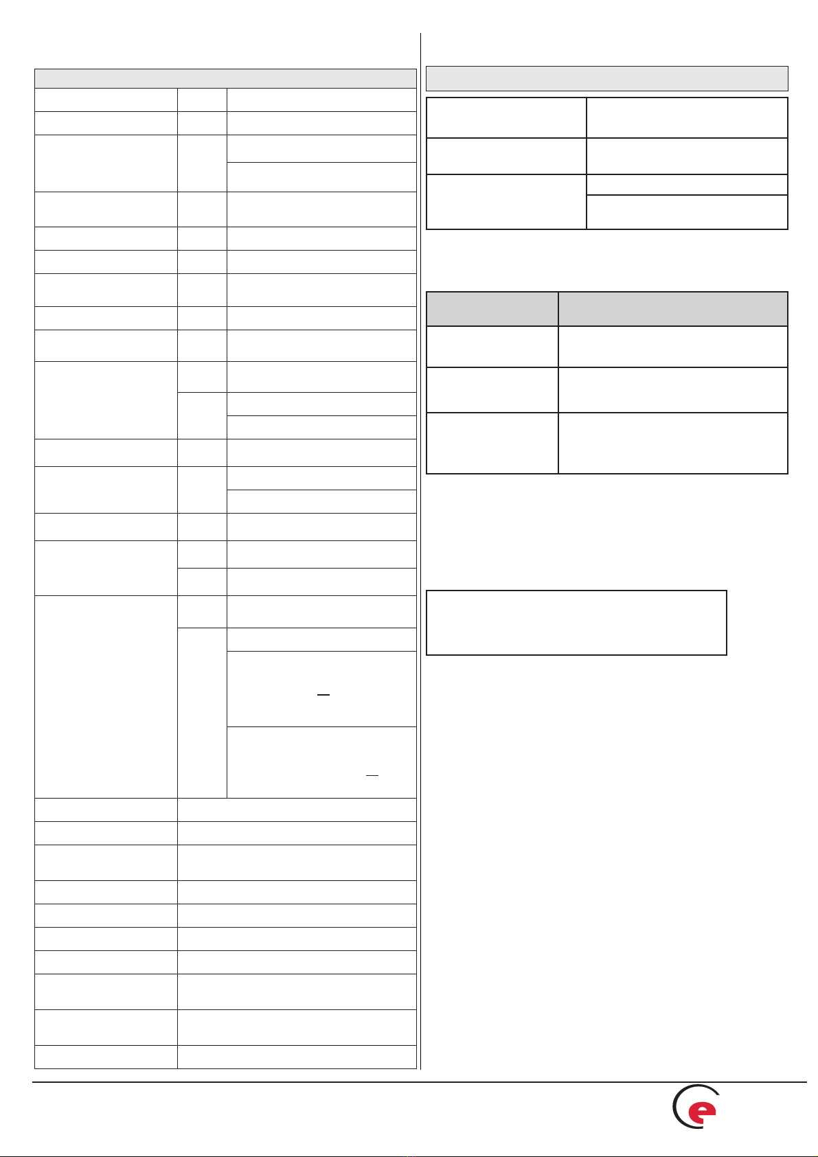
14 Technical Data
Calculator
Ambient temperature °C 5 ... 55
Temperature range °C 1 ... 150 °C (optional 1 ... 180 °C)
Temperature difference
heat K
3 K... 100 K
(3 ... 130 for temperature meas-
urement range 1 °C - 180 °C)
Temperature difference
cooling K -3 K... -50 K
Calculation of heat from K ∆Θ> 0.05
Calculation of cooling from K ∆Θ< -0.05
Dual-purpose heat/
cooling meter K∆ΘHC< -0.5
Resolution temperature °C 0,01
Measurement cycle 30 seconds
(with external power supply 4 sec.)
Power supply
stan-
dard
3,6 V lithium
(6+1 years)
optional 3V power pack
supply via M-bus
Pulse values stan-
dard see type identification
Pulse length min. pulse length 25 ms
min. pulse interval 25 ms
Display LCD 8 digits + special characters
Units
stan-
dard MWh
optional kWh, GJ
Interfaces
stan-
dard infrared
optional
M-Bus
2 potential-free contact outputs for
volume and energy
or
2 additional pulse inputs
(max. length of cable 10 m)
2 potential-free contact outputs for
heat- and cooling energy (dual-
purpose meters) or
2 additional pulse inputs
Data storage E2PROM / daily
Maximal value storage 3 each for flow and power
Billing dates annual billing date selectable
(from dd.mm. to dd.mm.)
Monthly values 24 monthly values readable
Protection class housing IP65
EMC class E1
Mechanical environment class M1
Pulse input device microcontroller CMOS input class IB as per
EN1434-2:2007
Dimensions length x width x height
198 mm x 123.7 mm x 45.8 mm
Weight approx. 250 g
Requirements for the temperature sensor pair
Platinum precision resistor Pt500; separately approved type
as per EN 60751
Length of connecting
cables (unshielded)
3 m in 2-wire technique
10 m in 4-wire technique
Installation
direct
in temperature pocket as per
EN1434
In the case of non-permanently attached temperature sensors
the temperature sensors that are later connected must meet the
following requirements:
Application Requirements for separate tem-
perature sensors
Heat meter EU (MID) identification on the tempera-
ture sensors
Cooling meter National approval as a temperature
sensor for cooling meters *)
Dual-purpose heat
and cooling meter
EU (MID) identification and
separate national approval as a
temperature sensor for cooling meters *)
*) Requirements in countries other than Germany may be different.
All classes refer to the currently valid legal requirements for heat
meters (see Declaration of Conformity).
15 Application of Configuration Software
Engelmann®Monitor
Available separately (including instructions).

Engelmann
The heat meter specialists
®
Engelmann Sensor GmbH, Rudolf-Diesel-Straße 24-28 , 69168 Wiesloch-Baiertal, Germany
Phone.: +49 (0)6222-9800-217 , Fax: +49 (0)6222-9800-50, E-Mail: [email protected], www.engelmann.de
Article-No. 1080700010 - 2011-04-01 Page 11
17 Disposal
This instrument contains a lithium battery.
This battery may not be opened by force, come into contact with
water, short-circuited, or subjected to temperatures over 80°C.
Dead batteries, and electronic instruments or components which are
no longer needed are hazardous waste and must be disposed of at
designated collection points.
Return shipment of the lithium batteries must be carried out approp-
riately.
19 Contact
Engelmann Sensor GmbH
Rudolf-Diesel-Straße 24-28
D-69168 Wiesloch-Baiertal
Germany
Phone: +49 (0)6222-98000-217
Fax: +49 (0)6222-9800-50
www.engelmann.de
E-Mail: [email protected]
Subject to technical change!
16 Error Codes
When the instrument detects an error, the error
symbol and number are displayed.
The error can also be displayed in binary form by selecting the
menu item 8) ‘error display’ in the first level / main loop.
There are seven possible causes of error, and they can appear in
combination with each other, depending on the situation.
At delivery, the display shows ‘ERR 03’ until temperature sensors
have been attached. This message disappears as soon as tempe-
rature sensors have been connected and the first measurement is
carried out (every 30 seconds for standard instruments).
Example: sensors switched
Error
Error code
Binary display
LCD
Check sum fault
E2PROM fault
Reset
Reference sensor fault
Return flow senso fault
Sensors switched
Forward flow sen. fault
Error
display
hexadeci-
mal (LCD)
When an error occurs, with the exception of the ‚reset’ and
‚sensors switched’ error, the instrument must be exchanged and
sent to the manufacturer for examination.
Recognition of switched temperature sensors is only activated
for meters which are purely heat meters or cooling meters.
Recognition of switched sensors is not possible for dual-purpose
heat / cooling meters.
18 MID Declaration of Conformity
For the product described in this document we confirm, as the
manufacturer, that it meets the fundamental requirements according
to the
• Council Directive 2004/22/EC of 31 March 2004 on the appro-
ximation of the laws of the member states relating to measure-
ment instruments, in particular those in annex MI-004, as well as
• the requirements relating to emissions in the European Council
Directive on EMC 2004/108/EC, and the requirements according
to the Council Low Voltage Directive 2006/95/EC.
The complete signed declaration can be found at
www.engelmann.de.
Using the binary display, it is easy to identify an error:
1 at 1st position: check sum fault
1 at 2nd position: E2PROM fault
1 at 3rd position: instrument has been reset
1 at 4th position: sensors switched
1 at 5th position: reference temp. sensor fault
1 at 6th position: return flow temp. sensor fault/not connected
1 at last position: forward flow temp. sensor fault/not connected


