ENGIE EPS easyWallbox User guide
INSTALLER MANUAL
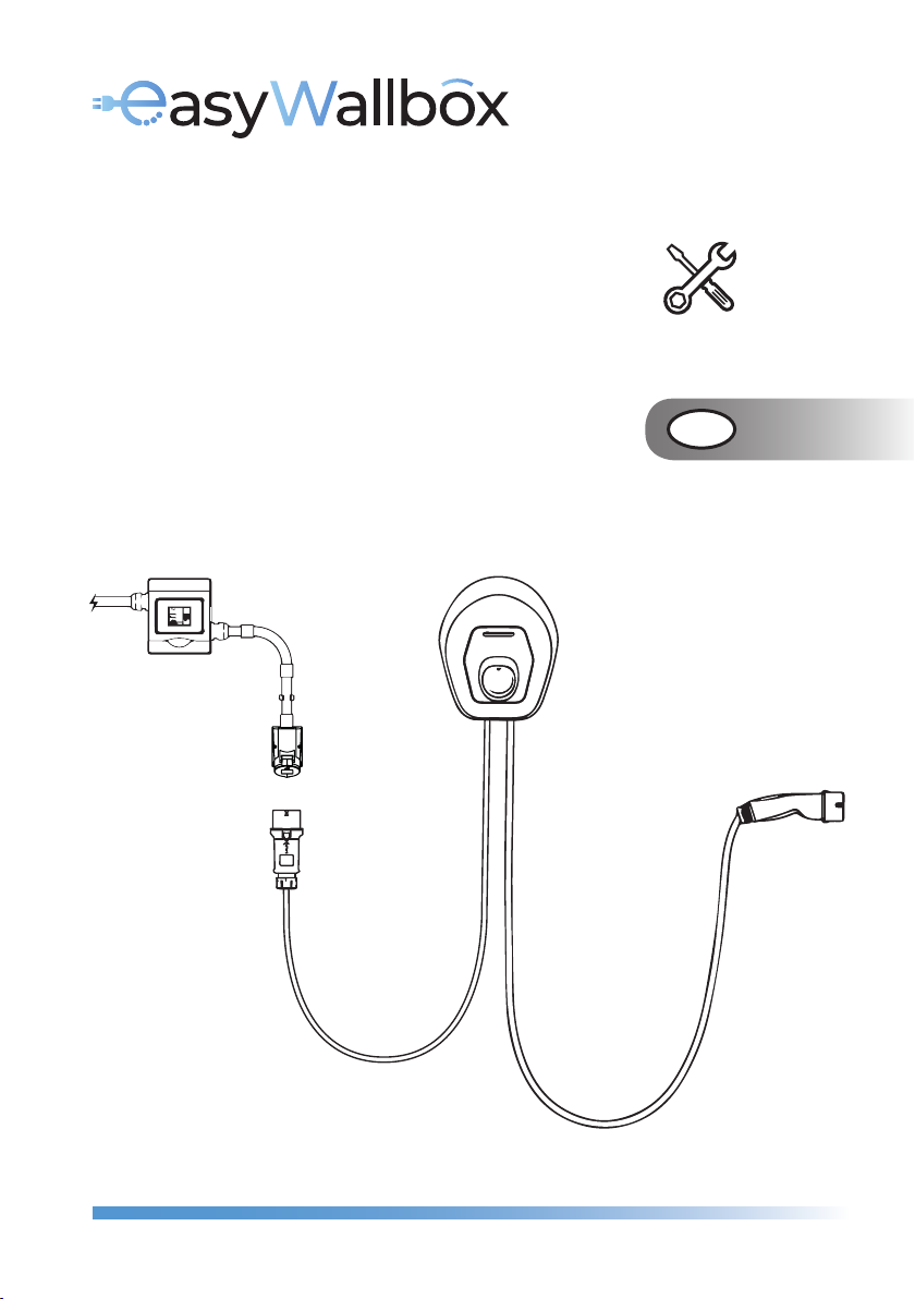
MODE 2 POWER UPGRADE GB

2 3
GB
GB
INDEX
1. ABOUT THE INSTALLER MANUAL 4
1.1. About installation in Mode 2 with Power Upgrade 5
1.2. Assistance 5
1.3. Symbols used 5
1.4. Warnings 6
2. SAFETY 8
2.1. Intended purpose of easyWallbox 8
2.2. Use not in accordance with the intended purpose 9
2.3. Essential safety instructions 10
2.3.1. Respect for local conditions 10
2.3.2. Respecting the supervision requirement 10
2.3.3. Regulatory status 11
3. PRODUCT DESCRIPTION 12
3.1. General description 12
3.2. Identification label 15
3.3. Technical features 16
3.4. Dynamic Power Management 17
3.5. Product versions country by country 18
4. INSTALLATION 18
4.1. Choice of position 19
4.2. Acceptable environmental conditions 20
4.3. What’s inside 21
4.4. Opening the package 22
4.5. Wall mounting 23
4.6. Power supply cable removal 26
4.7. Socket and plug installation instructions 28
4.8. Power supply connection 30
INDEX
4.9. Installation of the Dynamic Power Management sensor
(optional step) 32
4.10. Setting the rotary switch 34
4.11. Case reassembly 35
4.12. Configuration via easyWallbox PowerUp (service app) 36
5. FIRST START 38
5.1. Turning on easyWallbox 38
5.2. Configuration through the My easyWallbox app
(only for users) 39
6. CHARGING PROCEDURE 40
6.1. LED status indicator 41
7. STOP CHARGING 42
7.1. Charging process completion 43
8. MAINTENANCE 44
8.1. Ordinary maintenance intervals 45
9. DISMANTLING AND STORAGE 46
9.1. Disconnection from the power supply 46
9.2. Removal of the device from the wall 47
9.3. Storage 50
10. DISPOSAL 50
10.1. Disposal of the packaging 50
10.2. Taking out of service and disposal of easyWallbox 50
11. ASSISTANCE 51
DISCLAIMER 52
PAGESECTION PAGESECTION

4 5
GB
GB
1.1. About installation in Mode 2 with Power Upgrade
Following this procedure, easyWallbox can be correctly installed in
Mode 2 and be used up to 32 A, (7.4 kW) in compliance with IEC 61851-1:2017.
Installation of the product in Mode 2 with Power Upgrade must be
carried out carefully following the instructions in this manual.
We recommend contacting service for any questions or doubts con-
cerning easyWallbox’s use, installation and maintenance.
1.2. Assistance
For information on assistance, please refer to chapter 11.
1.3. Symbols used
DANGER
WARNING
CAUTION
ATTENTION
QUALIFIED
PERSONNEL
This symbol indicates imminent danger that
may cause death or serious injuries.
This symbol indicates a dangerous situation that
may cause death or serious injuries.
This symbol indicates a dangerous situation that
may cause slight injuries.
This symbol indicates a situation that may
cause material damage to easyWallbox.
Work that must be carried out by a technician,
from this point ‘Qualified Personnel’, qualified
to design, create a state-of-the-art domestic
electrical system and certify it in compliance
with local regulations and the energy supply
contract.
1. ABOUT THE INSTALLER MANUAL
Thank you for choosing easyWallbox. Please spend some minutes to
read the documentation to install and use it safely, discovering all its
advantages. easyWallbox is a revolutionary, easy-to-use charging station
for electric vehicles that can be installed both in Plug&Play mode, with
connection to the power supply by plug and cable, and Power Upgrade
mode, with permanent connection to the power supply.
The information in this manual is for easyWallbox installers and users
and concerns installation in Mode 2 with Power Upgrade, safe use,
and basic maintenance of the device.
This manual is intended only for installation in France with Power
Upgrade up to 32 A, for installation in other countries please refer
to Installer Manual.
Read the associated documentation carefully to acquire familiarity
with the instructions and safety indications before installing the
product.
This Installation requires qualified personnel, qualified to design
and create a dedicated, state-of-the-art power supply and certify
the domestic electrical system in compliance with local
regulations and the energy supply contract.
Before starting installation, qualified personnel who will make the
installation in Mode 2 with Power Upgrade should check they have
access to easyWallbox PowerUp with the credentials enabled for
access so that they can set-up the required parameters.
For installation in Plug&Play, see the relative documentation in the
User Manual.
6 7
GB
GB
The device must be connected to a power supply compliant with
all technical requirements indicated in this manual.
Children or other persons not able to evaluate risks related to
installation or use of the device might be seriously injured or risk
their own lives. Such persons must not operate the device and must
be supervised when close to it.
Pets or other animals must be kept away from the device and
packaging material.
Children must not play with the device, the accessories nor the
packaging provided with the product.
easyWallbox does not contain components that the user can
repair or maintain autonomously.
The only part that can be removed from easyWallbox is the aesthetic
cover, just during the installation and dismantling phases and
following the instructions. easyWallbox shall not be further opened,
unless by qualified personnel while performing installation,
dismantling or maintenance.
The power supply to easyWallbox must be installed on a dedicated
thermal-magnetic miniature circuit breaker (MCB) mounted in the
service panel to protect the electrical circuit. When dimensioning
the circuit breaker, the increased ambient temperatures in the
control cabinet must also be taken into account.
easyWallbox can only be used combined with an energy source.
easyWallbox must be treated and disposed of in compliance with
current legislation, separately from normal household waste as
electric and electronic waste (WEEE).
Always switch off power before any maintenance activity
Before installing easyWallbox, make sure that the power supply
used is switched off on the service panel.
1.4. Warnings
Danger of electric shock and fire
Before using easyWallbox, read the contents of this manual
carefully to acquire familiarity with the instructions for use and the
safety indications.
Before starting installation, be sure that easyWallbox is not
connected to any power supply. Any operation of installation,
maintenance and dismantling shall be done only when disconnected
from power supply.
Before connecting to a power supply, make sure that the electric
socket is installed correctly, with a proper ground connection and
in compliance with local and international standards.
Before installing or using the device, make sure that no damage
has occurred to any component. Damaged components can lead
to electrocution, short circuits, and fire due to overheating. A device
with damage or defects must not be used.
Install easyWallbox away from petrol cans or combustible
substances in general.
Before carrying out any maintenance operation, ensure that the
power supply is off.
Before installing easyWallbox in Power Upgrade mode, make sure that
the power supply you’re using is switched off on your service panel.
Before putting back or moving easyWallbox, ensure that the device
is not attached to the power supply.
Use of easyWallbox must be limited to the specific applications it
is intended for.
Installation, maintenance, or repairs not made correctly may lead
to risks for the user. Please ensure that easyWallbox is only used in
the correct operating conditions.
8 9
GB
GB
Before starting installation, installers in Power Upgrade mode
should check they have access to easyWallbox PowerUp with
credentials enabled to enter ‘Service Mode’ so that the required
parameters can be set up.
Installation should comply with IEC 60364-7-722 Low-voltage electrical
installations, Part 7-722: Requirements for special installations or
locations, Supplies for electric vehicles.
The installation should comply with local installation regulations.
easyWallbox is classified for electromagnetic compatibility (EMC)
environment type B.
2.2. Use not in accordance with the intended purpose
Use of easyWallbox is only safe if it conforms to the intended purpose.
Different use and unauthorised modifications to the device are considered
as non-compliant and so unacceptable. The user is responsible for the
use and is liable for any dangerous situations or situations contrary to
the legal provisions applied in their country.
ENGIE Eps does not assume any liability for damage caused by
non-compliant use or unauthorised modifications to the device.
2. SAFETY
2.1. Intended purpose of easyWallbox
easyWallbox is only intended for fixed mounting. It can be installed and
used to charge electric vehicles in areas with restricted access, both indoor
and outdoor (e.g. private housing, private parking areas or similar places), in
compliance with chapter 4 indications and local regulations.
The device can be used exclusively to charge full-electric or hybrid
vehicles compatible with Type 2 connectors, as in IEC 62196-2; it is not
compliant with other vehicles or devices.
The standard IEC 61851-1:2017, paragraph 6.2.2 prescribes as nominal current
and nominal voltage for Mode 2 respectively 32 A and 250 V in single-phase.
Hence easyWallbox power can be increased up to 7.4 kW (32 A) in
compliance with Mode 2 current and voltage limits, by using an
adequate cable and industrial connector suitable for 32 A and compliant
with IEC 60309-2.
Some countries apply regulations that require supplementary protection
from the risk of electrocution. In any case, the instructions for use in the
manual and any additional documentation must be read before using
easyWallbox. easyWallbox should be connected to a power supply
protected by an RCD and an overcurrent protective device. The RCD
should have a rated residual operating current not exceeding 30 mA, be
at least type A, and should comply with one of the following standards:
IEC 61008-1, IEC 61009-1, IEC 60947-2 and IEC 62423. RCDs should disconnect
all live conductors. The overcurrent protective devices should comply with
IEC 60947-2, IEC 60947-6-2, IEC 61009-1 or the relevant parts of IEC 60898
series or IEC 60269 series.
In the event of a short circuit, the value of I2t at the vehicle connector
(Case C) of the charging station should not exceed 80 000 A2s. easyWallbox
can be connected to TT, TN and IT types of earthing systems. For circuits in
IT systems that are intended to power electric vehicles, for example through
an isolation transformer or a battery system, an insulation control device
(IMD) compliant with CEI EN 61557-8 must be provided. In a TN system, a
circuit supplying a connecting point should not include a PEN conductor.
All the instructions in this Mode 2 with Power Upgrade Manual are only
intended to be carried out by qualified personnel with the abilities
described in 1.3, from this point ‘Installers in Power Upgrade mode’.
10 11
GB
GB
2.3. Essential safety instructions
easyWallbox was designed, built and checked in compliance with the
current safety regulations. Installation of easyWallbox in Mode 2 with
Power Upgrade can only be made by qualified personnel able to
understand and carefully follow these instructions and evaluate and
understand all related risks. ENGIE Eps does not assume any liability for
damage to persons or things that may arise from failure to respect the
safety regulations and the instructions in this manual.
2.3.1. Respect for local conditions
The operational safety of easyWallbox depends on its correct installation
which must respect current legislation.
Incorrect installation may cause danger such as serious injury
or death.
2.3.2. Respecting the supervision requirement
Children and people not able to evaluate, even momentarily, the pos-
sible risks arising from the incorrect use of easyWallbox must be kept
away from the device and the charging cable, both when in use and
non-operational.
2.3.3. Regulatory status
easyWallbox must be maintained intact. If there is any damage or
defects, users run the risk of serious injury caused by electric shocks.
Therefore, follow the instructions below:
avoid knocking the device
avoid use not in accordance with the intended purpose
avoid incorrect use of the device
clearly indicate the malfunction of the device so that other people
will not use it
ask for the prompt intervention of qualified personnel to repair
damage or defects.
Use of easyWallbox during a strong thunderstorm is not
recommended
12 13
GB
GB
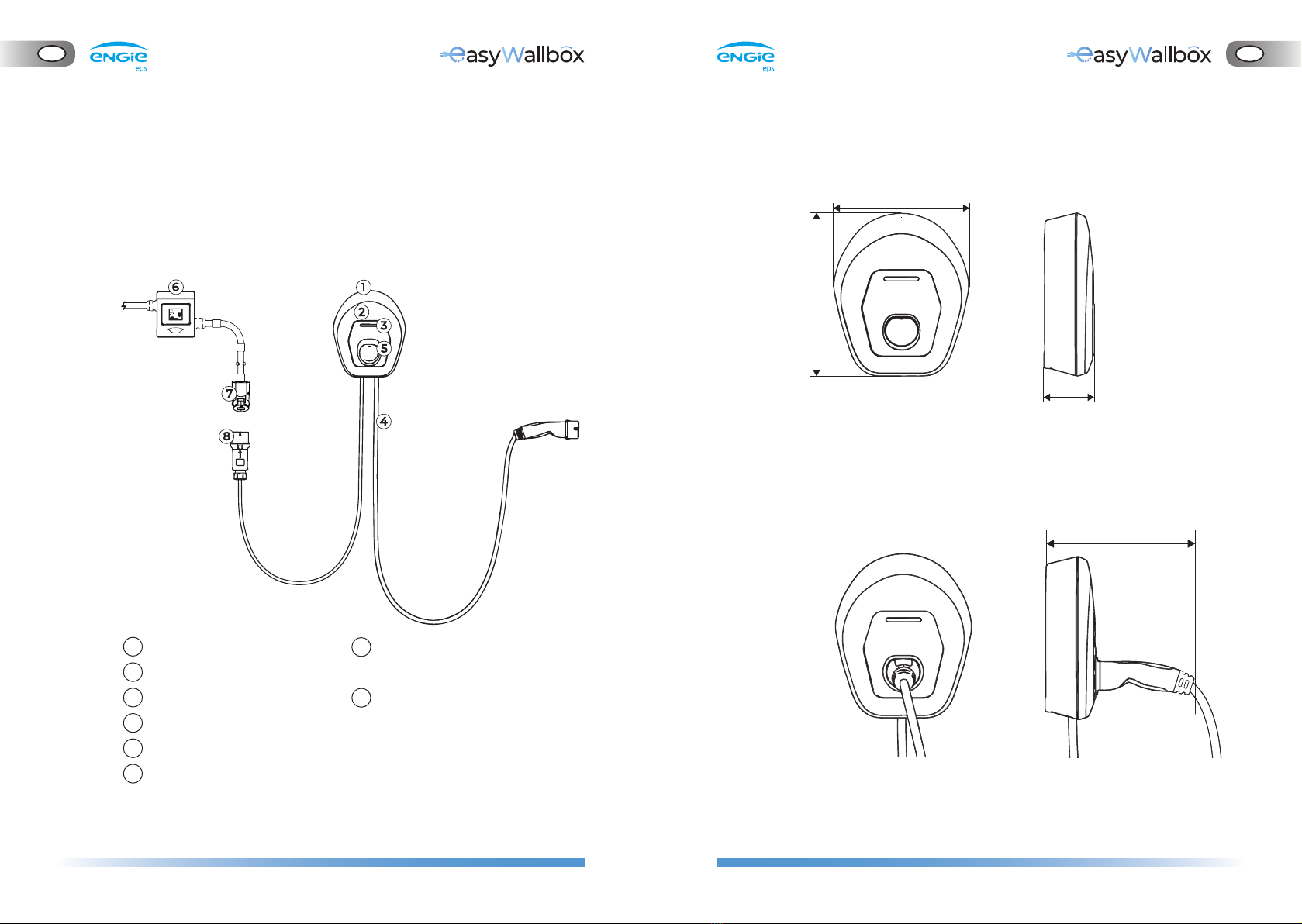
102 mm
277 mm
333 mm
102 mm
277 mm
333 mm
325 mm
325 mm
front view side view
32A industrial socket (compliant
with IEC 60309-1, IEC 60309-4)
32A industrial plug (compliant
with IEC 60309-1, IEC 60309-4)
Size of easyWallbox charging station
without connector in place
Size of easyWallbox charging station
with connector in place
1
2
3
4
5
6
3. PRODUCT DESCRIPTION
3.1. General description
The case of easyWallbox is in polycarbonate and ensures a high level of
stability and lightness. The design of the device is the result of in-depth
study intended to provide an ergonomic, lean and intelligent work tool.
Product description
Case
Aesthetic cover
LED status indicator
Cable with Type 2 connector
Type 2 connector port
Electrical Installation with
protection and cabling
(not included)
6 - 7 - 8 NOT INCLUDED
7
8
front view side view
14 15
GB
GB
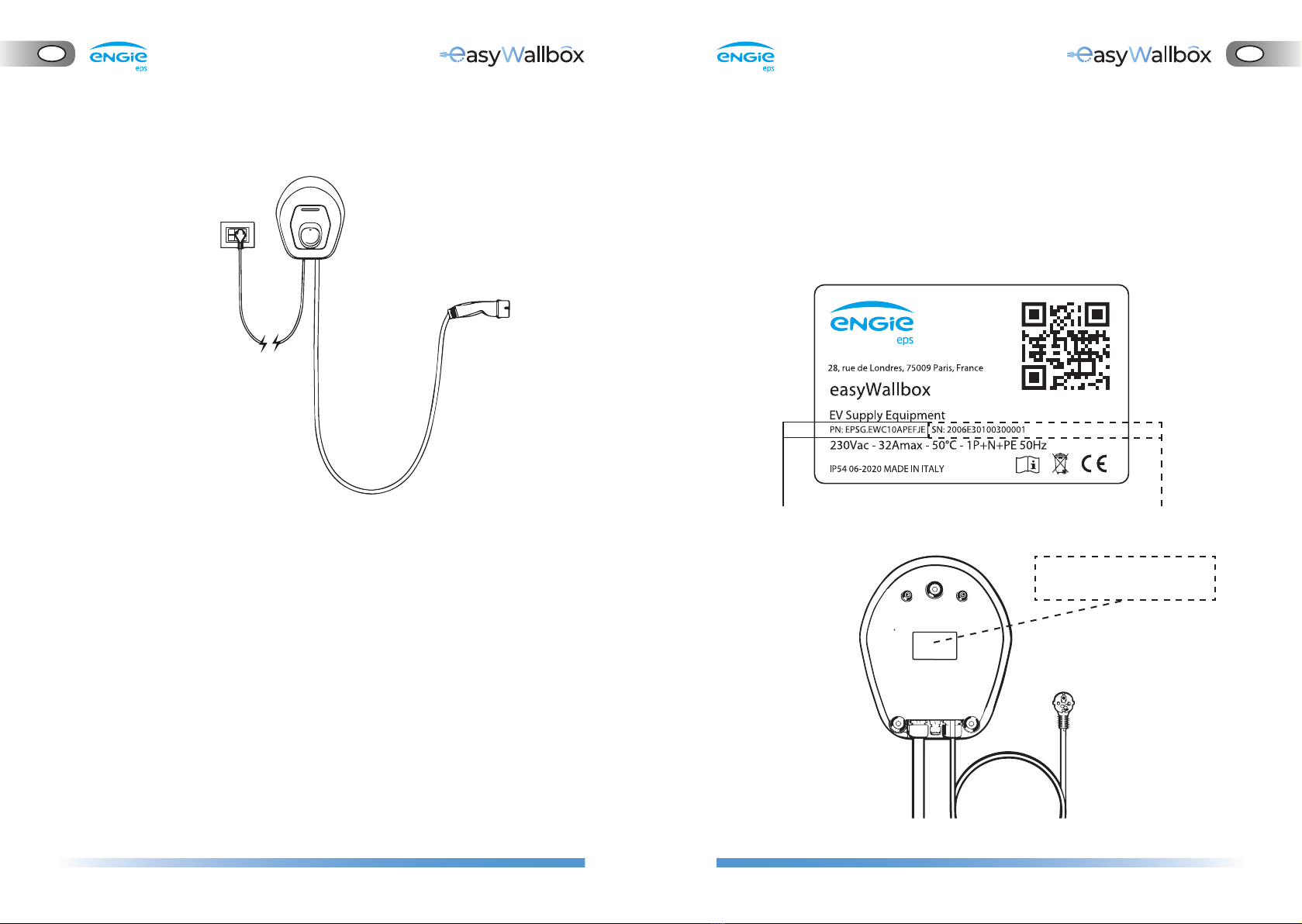
3.2. Identification label
The identification label is on the backside of the charging station.
The information on the label is shown in the Figure below. The data
shown may differ from that in the Figure, depending on the version
of the product.
Installation of easyWallbox in Plug&Play mode (see User Manual)
label position
(rear view)
model name serial number
16 17
GB
GB
3.3. Technical features
Plug&Play Power Upgrade
Description
Connector Standard (EV side) IEC 62196-2
Power supply plug E/F (G in UK, J in Switzerland)
EVSE Standard IEC 61851
CE Mark Y
Warranty 2 years
Recharging Mode Mode 2 Mode 2
TÜV Certification Y Y
Electrical Specs and connection
Maximum Power [kW] up to 2.3* up to 7.4*
Voltage [V / Hz] 230 / 50, single-phase 230 / 50, single-phase
Current [A] up to 10* up to 32*
Stand-by consumption [W] < 2 < 2
Cable with connector Type 2 (EV side) Y, tethered included
Cable with connector Type 2 Length [m] 3
Power Supply cable [m] 6 N.A.
* The values may vary in some countries according to local applicable standards
General Specs
Enclosure ratings IP54, IK08 (IEC 60529)
Overall body dimensions [mm] “335 x 277 x 95 (w/o Plug)
335 x 277 x 350 (with plug)”
Housing Polycarbonate
Weight [kg] ~ 4
Standard Body colour Black (RAL 9011) and White (RAL 9010)
Status indication Y, led RGB
Safety and Operation
Temperature range [°C] -25 / +50 (without direct exposure to sunlight)
Overheating protection Y
Humidity Resistance Y, full coated
Class of Protection I
Pollution Degree PD3
Overvoltage category OVC III
Housing fire ratings UL94 V-0
Residual current monitoring Y, 6 mA DC sensitive RCM device included for DC-leakage detection
Maximum installation height [m] 2000 a.s.l.
Connectivity & Special Features
Bluetooth Y
Smartphone App My easyWallbox, compatible with Android, IOS
Service App easyWallbox PowerUp compatible with Android
Android version compatibility** Lollipop (5.0) or higher***
IOS version compatibility** 12 or higher
Communication Protocol Proprietary
Dynamic Power Management Y, by installing the included sensor
** Data refer to the first release of the APP and may vary with future evolution
*** Not for Android 6
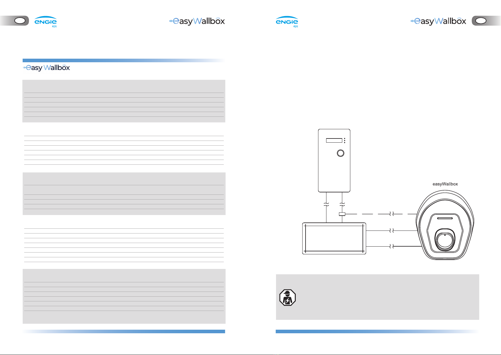
281175 code
METER
CURRENT
SENSOR
MAIN SWITCHBOARD
3.4. Dynamic Power Management
easyWallbox includes Dynamic Power Management (DPM), a smart
function that modulates the charging power according to power
availability, thus avoiding unpleasant blackouts.
To activate the Dynamic Power Management, please see chapter 4.8 on
installation of the sensor.
easyWallbox can work even without Dynamic Power Management; in
this case, the installation of a dedicated sensor is not necessary, but
avoidance of blackouts is not ensured.
- Connection of the Dynamic Power Management sensor requires
installation by a professional.
- We recommend contacting qualified personnel or service for any
questions or doubts concerning easyWallbox’s use, installation,
and maintenance.
18 19
GB
GB
- The installer in Power Upgrade mode should follow best practices
for electrical installation of appliances with local regulations and
international standards.
- ENGIE Eps does not assume any liability for damage caused by
non-compliant use or unauthorised modifications to the device.
already installed?
YESNO
Go to Cap. 4.4 Go to Cap. 4.6
already
installed?
NO YES
3.5. Product versions country by country
easyWallbox is designed to provide up to 7.4 kW of charging power in
Power Upgrade mode. However, the maximum power depends on
different factors, including local regulations for such a device.
The settings for easyWallbox maximum power should only be made by
qualified personnel who follow this manual carefully in compliance with
local regulations, international standards and any constraints on the
existing domestic electrical system.
4. INSTALLATION
Go to paragraph 4.1 Go to paragraph 4.6
4.1. Choice of position
easyWallbox is only for fixed wall mounting, and therefore cannot be
used in different spaces where its continual movement is required.
Before installing the device, check the feasibility. In detail, the position
chosen for the installation of easyWallbox must:
be on a vertical and flat surface, as shown in 4.5; weak surfaces that
do not ensure a robust resistance must be avoided
allow easy connection to the power supply and to the electric vehicle
to charge
not be an obstacle to the movement of the electric vehicles to charge
not have material or equipment on the whole of the surface required
for the installation
respect local legislation on electrical installations, fire prevention
measures and rescue methods in the installation site
easyWallbox must not be installed in places:
at risk of explosion (EX environment)
used for escape routes
where articles may fall on it (e.g. suspended ladders or car tyres) or
where it is prone to be hit and damaged (e.g. close to a door or in
vehicle operating spaces)
where there is a risk of pressurised jets of water (e.g. because of
washing systems, power washers or garden hoses).
20 21
GB
GB
3
5
6
4
1
2
4.2. Acceptable environmental conditions
In detail, the conditions of the room where easyWallbox is sited must
be as follows:
room temperature between -25°C and +50°C
average temperature over 24 hrs less than 35°C
maximum altitude above sea level: 2,000 metres
relative air humidity not higher than 95%
Damage to easyWallbox caused by unsuitable environmental
conditions.
Inappropriate positioning of easyWallbox may cause damage to
the device.
Take the following into consideration when choosing the position for
the installation of easyWallbox:
avoid exposure to direct sunlight, if necessary, by installing a canopy
avoid direct exposure to the rain so that deterioration due to bad
weather does not occur
ensure sufficient ventilation for the device – do not mount it inside a
niche nor a closet
avoid an accumulation of heat - keep the device away from heat
sources
avoid exposure to water infiltrations
avoid excessive leaps in temperature
Danger of fire and explosion
easyWallbox must be installed in areas where there are no
incendiary or explosive substances, such as close to petrol
stations, because any sparks triggered by its components could
cause fires or explosions.
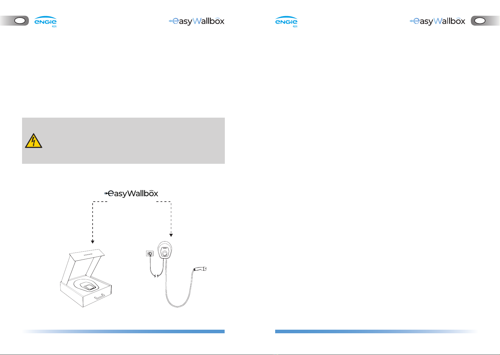
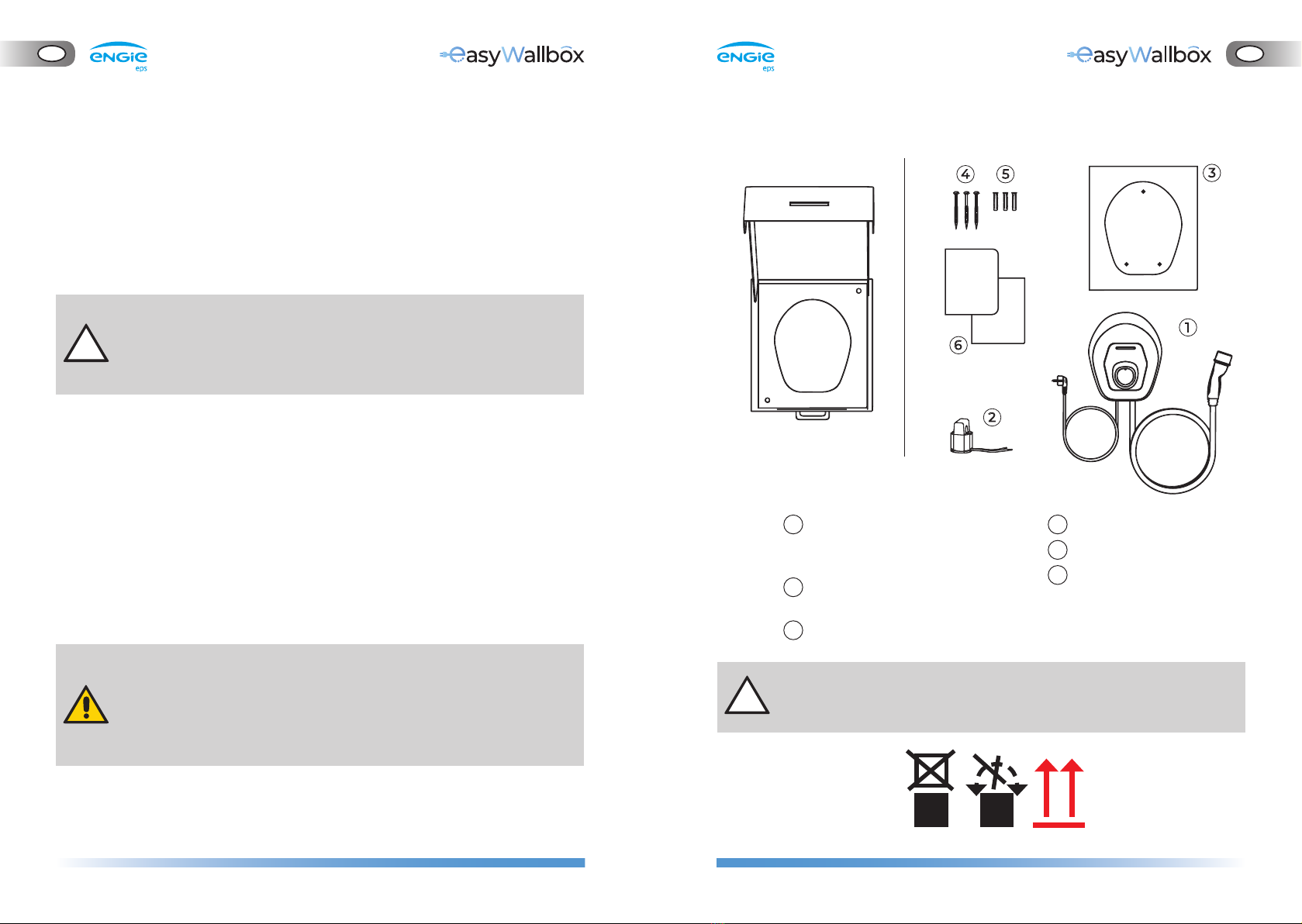
4.3. What’s inside
easyWallbox package contains:
Do not stack loads on the box containing easyWallbox and pay
attention to the signs and specific instructions on the package.
easyWallbox, including cables,
power supply plug and
charging connector
Current sensor for Dynamic
Power Management (DPM)
Drilling template
1
2
3
4
5
6
3 Screws
3 Fixing Plugs
Manuals and product
certificate
22 23
GB
GB
2 31
6
5
4
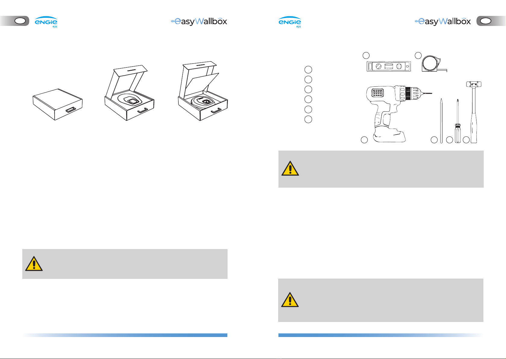
4.4. Opening the package
When the box is opened, check that the various parts of easyWallbox
do not show signs of physical damage caused by knocks, lacerations or
abrasions. If damage is detected installation must be interrupted
immediately and the type of damage reported to the seller. If necessary,
contact assistance as explained in 11.
The individual components of the device are protected by PVC
packaging and sealed with adhesive tape. When the box is opened, the
parts should be cleaned to remove any dust, PVC residues or portions of
adhesive tape.
easyWallbox must only be taken from the box when everything has
been prepared for the installation and it must be transported manually
to the wall chosen for its installation.
When easyWallbox is moved manually, do not trip on the power
supply cable of the vehicle.
Closed box containing
easyWallbox
Opening the lid of the box
containing easyWallbox
Raising the panel
in the box with easyWallbox
4.5. Wall mounting
ENGIE Eps declines any liability for damage to persons or things
that may arise from the use of such tools. We recommend
contacting qualified personnel or service for any question or
doubt concerning easyWallbox installation.
The national and international building regulations and the directives
defined by the International Electrotechnical Commission IEC 60364-1
and IEC 60364-5-52 must be respected when fixing easyWallbox to the wall.
Correct positioning of the charging station is important for its operation.
When the installation wall is chosen for easyWallbox, take the
distances of the connection to the power supply and the connector
on the vehicle into consideration as well as the parking and
manoeuvring space available.
If several easyWallboxes are installed close together, there must be at
least 20 cm between each one.
easyWallbox must be installed at a height of 1.30-1.40 m from the floor.
Risk of electric shock.
Before starting installation, be sure that easyWallbox is not
connected to any power supply. Any operation of installation,
maintenance and dismantling shall be done only when power
supply is switched off on your service panel.
Drill
Pencil
Screwdriver
Hammer
Spirit level
Measure tape
tools not included
1
2
3
4
5
6
12 3 4
5 6
24 25
GB
GB
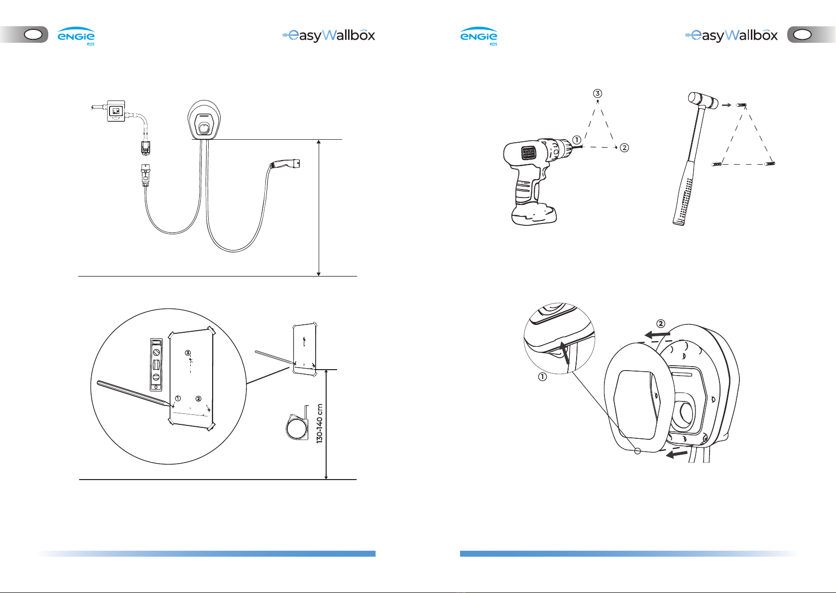
130-140 cm
12
3
4. Remove the aesthetic cover of easyWallbox set up by mechanical
interference in the CASE, using the groove on the bottom.
2. Use a drill to make the holes
in the wall.
3
1
2
3. Put the fixing plugs into the
holes using a hammer.
1
2
130 - 140 cm
Wall-mounting height for easyWallbox.
Follow the steps below.
1. Using the drilling template (A3 sheet), mark where to drill on the
wall, using a measure tape and a spirit level.

26 27
GB
GB
2. Remove the power cable
Disconnect the wires connected to the tool-free J1 ‘push-lock’
terminals (4)
Disconnect the earthing wire connected to the J3 ‘Faston’
terminal (2)
Remove the power cable from the cable gland (A)
The power cable shall be stored where it can cause no danger
to anybody (e.g. risk of tripping) and where no damage can occur
to it while stored.
12
34
2
4
A
5. Place easyWallbox in correspondence with the holes and fix it to
the wall using the screws supplied.
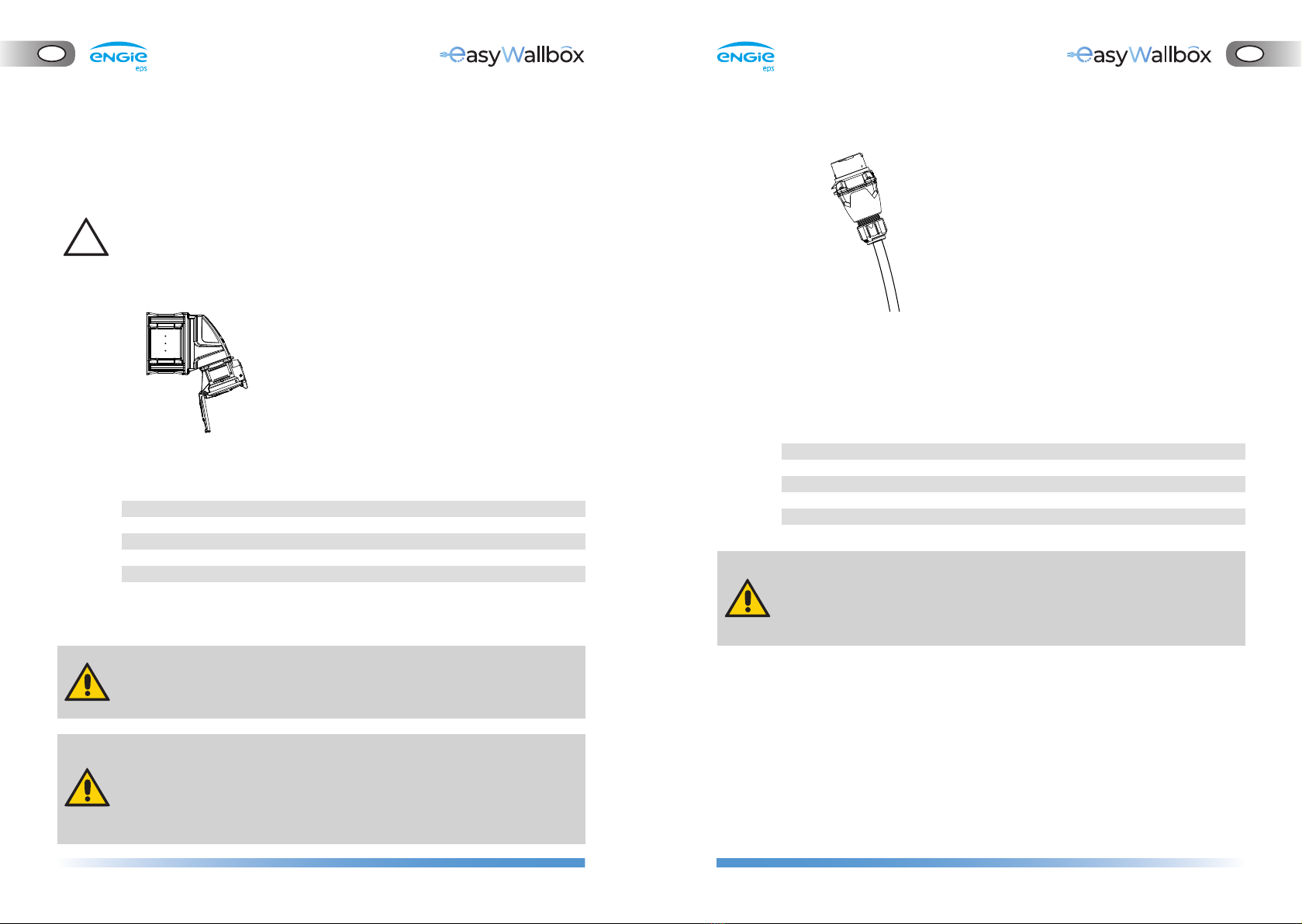
4.6. Power supply cable removal
If easyWallbox was already installed in Plug&Play mode, remove the
aesthetic cover as indicated in step 4 before proceeding with the next steps.
Risk of electric shock.
Before starting installation, be sure that easyWallbox is not
connected to any power supply. Any operation of installation,
maintenance and dismantling shall be done only when power
supply is switched off on your service panel.
1. Remove the front panel of easyWallbox.
3. Store the power cable with the others
easyWallbox accessories for use again
in Plug&Play mode
28 29
GB
GB
Plug installation
Install a 32 A plug (male connector), providing it with adequate cabling,
with length and section adequate to connect easyWallbox to the
installed 32 A Socket.
The 32 A plug shall have the following features:
Risk of electric shock.
Any operation of installation, maintenance and dismantling
shall be done only when power supply is switched off on your
service panel.
Amperage 32A
Poles 3P (2P + PE)
Nominal Voltage 230 V
Frequency 50 Hz
Reference Standard IEC 60309-1, IEC 60309-4
4.7. Socket and plug installation instructions
Once the power supply cable is removed, as explained in chapter 4.6
please act as follow.
The socket and plug should be compliant with French standard UTE
C15-722 “Supply of electric vehicle and plug-in hybrid electric road
vehicle - Installations électriques à basse tension”
Socket installation
A 32 A socket (female connector) installed close to easyWallbox
installation position is required, having the following requirements:
Both wall-mounting and switchboard-mounting versions of the socket
are acceptable.
Risk of electric shock.
Any operation of installation, maintenance and dismantling shall be
done only when power supply is switched off on your service panel.
All safety requirements concerning RCD and MCB installation listed
in chapter 2.1 should be followed.
If not present, proceed with the installation of the socket in proximity
of easyWallbox. For the installation, please refer to the plug specific
instructions. Once installed, please proceed to next instruction.
Amperage 32A
Poles 3P (2P + PE)
Nominal Voltage 230 V
Frequency 50 Hz
Reference Standard IEC 60309-1, IEC 60309-4

30 31
GB
GB
4.8. Power supply connection
Risk of electric shock.
Before starting installation, be sure that easyWallbox is not connected
to any power supply. Any operation of installation, maintenance and
dismantling shall be done only when power supply is switched off on
your service panel.
Insert the power supply wires through the cable gland (A)
Shorten the connection wires to the appropriate length (avoid
leaving too much cable margin). The protective conductor PE must
be longer than the other conductors.
Connect the cables to the J1 tool-free ‘push-lock’ terminals (4).
Connect Line (L) and Neutral (N) as indicated on the board.
We recommend using flexible cables with the following max. section:
- 6 mm
Connect the earthing wire to the J3 ‘Faston’ terminal (2).
We recommend using FEMALE 6.3 x 0.8 ‘Fastons’, better if with restraint.
WARNING
2
4
A
Incorrect installation may cause danger such as serious injury or death
The power supply to easyWallbox must be installed on a dedicated
thermal-magnetic miniature circuit breaker (MCB) mounted in the
service panel to protect the electrical circuit.
The minimum characteristics of the MCB: voltage 250V, nominal
current 32A (in the hypothesis of absorption of the maximum power
equal to 7.4kW). If local regulations do not allow maximum power to
be absorbed, the installer must evaluate the choice of a circuit-breaker
with rated current based on the maximum power allowed in the state
of installation, a type C curve for domestic or similar use is suggested
as the trip curve.
When dimensioning the MCB, the higher ambient temperatures in
the control cabinet must also be taken into account.
When dimensioning the MCB, the prospective short-circuit current
should be considered. As an indicative value 5kA could be considered
but a precise evaluation must be done before installation. The
maximum interrupting capacity of the MCB must be greater than the
evaluated prospective short-circuit current.
The MCB must be in line with the section of the wires.
The installation must incorporate a dedicated and adequate residual
current device (RCD/ fault-current circuit breaker). An RCD with at
least Type A must be used since easyWallbox has an internal DC fault
current monitoring of ≥ 6 mA by using an RCM device with a
maximum rated primary current of 80A.
Two 1A and 250V fuses are integrated in the easyWallbox on the logic
supply channel.
Be aware that local regulations may be applicable and may vary
depending on your region/country of residence. easyWallbox must be
installed according to the local regulations.
ENGIE Eps does not assume any liability for damage caused by
non-compliant installation of the device. Installer in Power Upgrade
mode is responsible for completing the installation at a state-of-
the-art technical level and in compliance with applicable regulation.

32 33
GB
GB
4.9. Installation of the Dynamic Power Management sensor
(optional step)
If the Dynamic Power Management is not required, please go to
chapter 4.10.
easyWallbox can work even without Dynamic Power Management:
in this case the installation of a dedicated sensor is not necessary,
but blackouts avoidance is not guaranteed.
Please read the following instructions carefully before installing the
dedicated Dynamic Power Management (DPM) sensor.
- The connection of the Dynamic Power Management sensor
requires an installation by a professional.
- We recommend contacting qualified personnel or service for any
question or doubt concerning easyWallbox’s use, installation, and
maintenance.
281175 code
METER
CURRENT
SENSOR
MAIN SWITCHBOARD
B
6
A = 25.5 mm
B = 10.2 mm
C = 40 mm
D = 5.91 mm
E = 26.5 mm
F = 6.1 mm
To connect the current sensor:
a. The current sensors must be attached to a single meter output
wire.
b. The sensor has a hinge and locking snap which allows attachment
without interrupting the live wire.
c. Join the current sensor wires and twisted cable (recommended
section 0.5 mm2).
d. Bring the twisted cable near easyWallbox.
e. Insert the twisted cable through the cable gland (B).
f. Connect the twisted cable to the J7 ‘push-in’ spring terminals (6)
without tools. There is no particular requirement about cabling
position on the terminal.
34 35
GB
GB
4.10. Setting the rotary switch
The installer in Power Upgrade mode should correctly set the Rotary
Switch following the instructions:
1. If the DPM sensor is not installed, choose POSITION 1
2. If the parametrization of DPM will be configured via App, choose
POSITION 2 and configure it asyWallbox PowerUp (chapter 4.12)
3. As an alternative, configure the DPM operation and limits in
accordance with the user’s energy supply contract, following Table 1,
Rotary Switch default DPM
A list of meanings of the Rotary Switch positions follows:
POSITION 0: Not allowed (reserved)
POSITION 1: DPM is always turned off
POSITION 2: DPM can be enabled or disabled via the asyWallbox
PowerUp (see chapter 4.12) or My asyWallbox (see chapter 5.2))
POSITION 3 to POSITION 9: DPM operations depends on the corre-
sponding max power values [kW] set by default
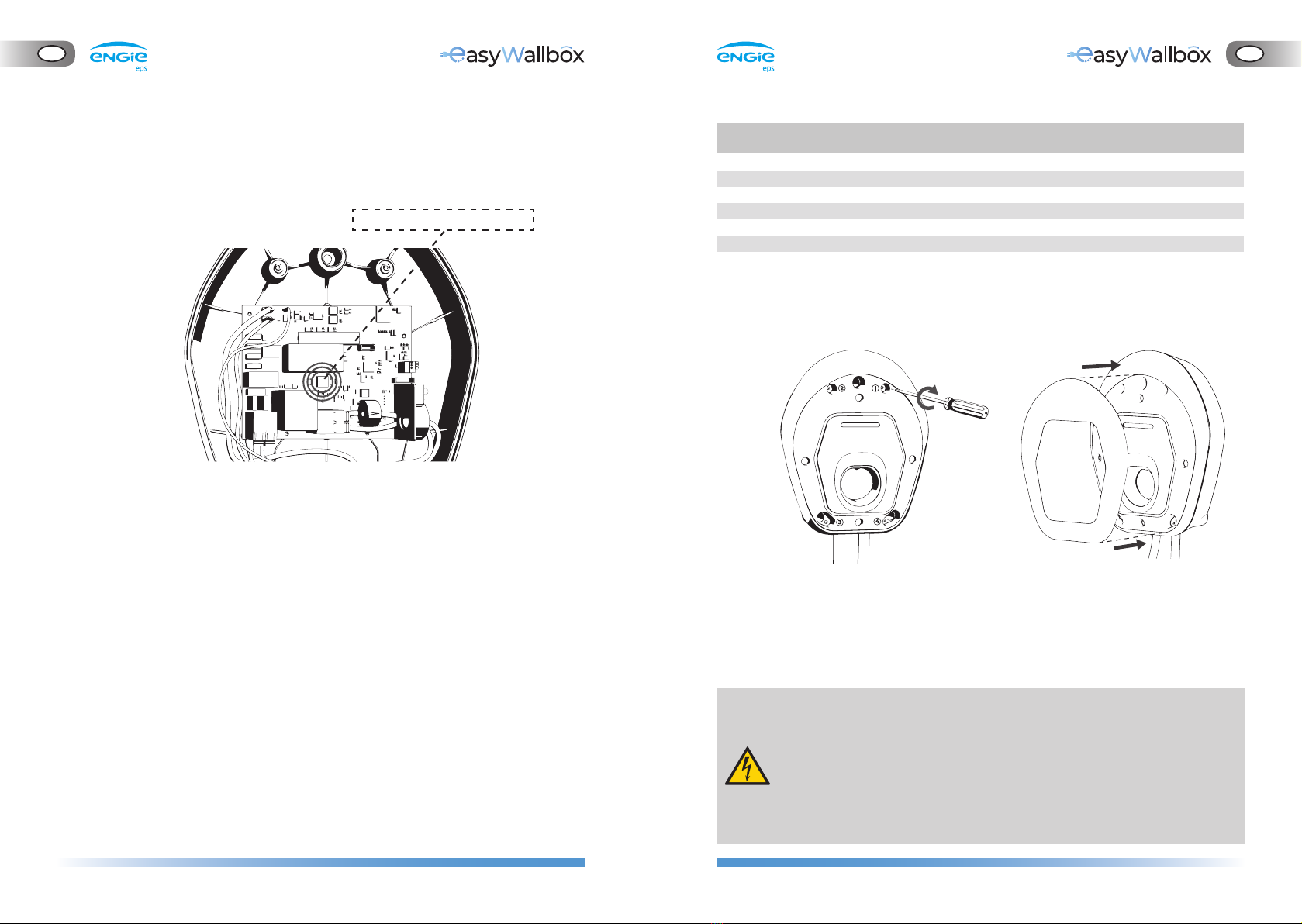
4.11. Case reassembly
1. Reassemble the front panel
of easyWallbox
3. Once easyWallbox has been mounted on the wall and connected
to the power supply, switch on power supply on your service panel.
- Before connecting to a power supply, make sure that easyWallbox
is installed correctly, with a proper earth connection and in
compliance with local and international standards.
- ENGIE Eps does not assume any liability for damage caused by
non-compliant installation of the device. Installers in Power Upgrade
mode are responsible for completing the installation at a state-of-
the-art technical level and in compliance with applicable regulations.
Rotary Switch (U14)
U14 Position DPM Current [A] DPM Power [kW]
3 13 3.0
4 16 3.7
5 20 4.6
6 25 5.8
7 32 7.4
8 43 9.9
9 49 11.3
Table 1 – Rotary Switch default DPM current
12
34
2. Reposition the aesthetic cover

36 37
GB
GB
4.12. Configuration via easyWallbox PowerUp (service app)
The final configuration for installation should be done via the purpose-
built app, easyWallbox PowerUp, only available for Android devices
from Google Play.
In detail, qualified personnel who install in Power Upgrade mode should
authenticate this, thus unlocking access to safety-relevant configuration
parameters. The most important for correct operation is the safety limit
on current absorption from the supply. Be aware that easyWallbox will
not charge EVs plugged in Power Upgrade mode unless properly confi-
gured in accordance with the following directions via the app.
The maximum charging current in Power Upgrade mode (‘Safety limit’)
must be the minimum value between the:
current allowed by the installed power supply, including wiring
sections
current allowed by local applicable standards.
The installation and parameter set-up should be in accordance
with local applicable standards. Please check local updates of
standards before setting up parameters.
The following table contains indicative values of maximum currents for
each installation country, to be checked however before any installation:
1. Open easyWallbox PowerUp on your smartphone.
2. Authenticate with your qualified personnel credentials.
3. Scan the authentication QR code available (see chapter 5.2)
4. Enter the ‘Safety limit’ determined according to the above
instructions. This must comply with local applicable regulations and
consistent with the maximum current allowed by the supply wiring.
5. If easyWallbox is configured with the rotary switch (U14) in position 2,
the app defines whether DPM is enabled:
a. If you did not install the sensor in accordance with section 4.9,
set ‘DPM’ to Off.
b. If you installed the sensor in accordance with section 4.9, set
‘DPM’ to On and ‘DPM limit’ in accordance with the user’s energy
supply contract.
6. Make sure that the ‘User limit’ is set to a value lower than or equal to
‘Safety limit’ and compatible with the user’s energy supply contract.
If the instructions in this paragraph are not followed, all
parameters remain as initially set for Plug&Play mode.
This reduces easyWallbox’s performance.
Country
Current limit with
Power Upgrade [A]
1. Germany 20
2. France 32
3. UK 32
4. Belgium 22
5. Luxembourg 32
6. Netherlands 22
7. Switzerland 16
8. Austria 16
9. Poland 32
10. Greece 32
Country
Current limit with
Power Upgrade [A]
11. Czech Republic 25
12. Slovakia 20
13. Hungary 32
14. Denmark 16
15. Sweden 32
16. Italy 26
17. Spain 32
18. Portugal 32
19. Norway 32

38 39
GB
GB
5.2. Configuration through the My easyWallbox app (only for users)
My easyWallbox is a dedicated smartphone App, available both on
Google Play®and App Store®, that can be used to configure, monitor,
and set easyWallbox via a Bluetooth connection.
Start and stop: Charging processes can be started and stopped, the
charging session delayed and access gained to the log of the latest
charging sessions through the app.
- If the instructions in paragraph 4.12 are not followed, all
parameters remain as initially set for Plug&Play mode. This
reduces easyWallbox’s performance.
- Simultaneous use of My easyWallbox and smart charging function
from the vehicle may lead to minor functional issues.
To authenticate the smartphone, frame the QR code as required by the
app tutorial. For detailed instructions please refer directly to the app.
5. FIRST START
5.1. Turning on easyWallbox
The device does not have start/stop buttons. Once installed, it is ready to
charge when there are the following conditions:
correct installation, carried out following the instructions in this
manual
regular status of the device
Danger of electric shock when the device is damaged. Use of a
damaged device may generate electrical discharges.
If the device is damaged, follow the instructions below precisely to avoid
dangerous situations, with the resulting damage to persons or things:
avoid using the damaged device
clearly indicate the damaged device so that other people will not use it
call qualified personnel promptly so that the device can be repaired
or, if irreparably damaged, taken out of service
Other manuals for easyWallbox
2
Table of contents
Other ENGIE EPS Batteries Charger manuals


 operating instructions")


