Thrane&Thrane CH4656 User manual

Battery Charger
T e c h n i c a l M a n u a l
Valid for:
CH4656
CH4666
CH2410

Please Note:
Any responsibility or liability for loss or damage in connection with the use of this product and
the accompanying documentation is disclaimed. The information in this quick guide is furnished for
informational use only, is subject to change without notice, may contain errors or inaccuracies, and
represents no commitment whatsoever. This agreement is governed by the laws of Denmark.
Doc. No.: M4656COM Issue: C/0508

Contents Battery Charger
CONTENTS
BATTERY CHARGER
1 INTRODUCTION 1-1
1.1 GENERAL DESCRIPTION 1-1
1.2 TECHNICAL DATA 1-1
2 TECHNICAL DESCRIPTION 2-1
2.1 PRINCIPLE OF OPERATION 2-1
3 INSTALLATION 3-1
3.1 OUTLINE AND DIMENSIONS 3-1
3.2 MOUNTING POSSIBILITIES 3-1
3.3 INSTALLATION WIRING 3-2
3.4 BLOCK DIAGRAM 3-3
3.5 AC SUPPLY VOLTAGE SETTING 3-4
3.6 CONNECTIONS 3-4
3.7 FLOAT CHARGE VOLTAGE ADJUSTMENT 3-6
4 SCHEMATIC DIAGRAM AND COMPONENT LOCATION 4-1
4.1 POWER SUPPLY UNIT 4-1
5 PARTS LIST 5-1
6 ACCESSORIES INCLUDED 6-1
0048


1-1
1 Introduction Battery Charger
BATTERY CHARGER
1 INTRODUCTION
1.1 GENERAL DESCRIPTION
The Battery Charger is designed as a stand alone unit.
The Battery Charger is designed with four separately fused output lines to ensure independent
supply for connected equipment if battery and Battery Charger is used in an uninterruptible power
supply (UPS) conguration.
Furthermore the Battery Charger includes the following features:
• 115V/230V selectable input.
• Encapsulation class IP22.
• Galvanic isolated AC alarm output.
• Protected Battery monitoring output.
• Indication of oat charge or main charge.
• Charges open or sealed lead-acid batteries.
• Easy connection.
• Easy access to fuses.
• Vertical or horizontal mounting.
• IEC 945 approved.
0048

1-2
1 Introduction Battery Charger
1.2 TECHNICAL DATA
AC input voltages: 115V, range 88V - 132V or 230V, range 176V - 264V.
Manual setting.
AC input frequency: 50/60 Hz ± 6%
Float charge voltage: Adjustable 26.8V - 28.8V to voltage specied by battery manufacturer.
Potentiometer located under cover.
Main charge current: 10A continuous.
Charger type: Automatic, with oat charging. IE characteristic.
Battery type: Lead-acid, open or sealed.
Nominal battery capacity: 20 - 120 Ah
Nominal charging time: 10 hours to 80% capacity, 120 Ah battery.
Battery monitoring: Protected output.
AC Mains Alarm output: Relay contacts 5-50mA, 10-32V. Closed in alarm condition.
Alarm in case of AC supply failure.
Protection: The Charger output is current limited and protected against polarity
reversal, short circuit, over voltage and over temperature.
Operating temperature: - 20° to + 55° C.
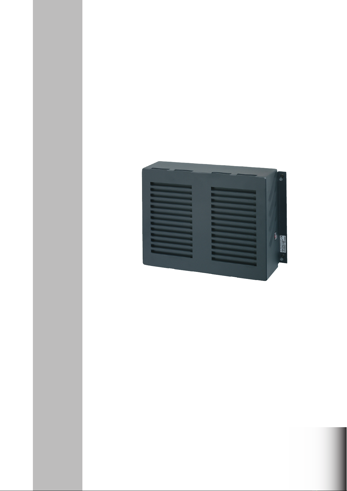
Dimensions: HxWxD: 110x370x260 mm.
Weight: Approx. 5 kg.
Compass safe distance: Standard: 1.4 m. Steering: 1.0 m.
0048

2-1
2 Technical Description Battery Charger
2 TECHNICAL DESCRIPTION
2.1 PRINCIPLE OF OPERATION
When charging the Battery Charger is operating as a constant current generator until the battery
voltage reaches the voltage level set by the oat voltage potentiometer. At this level the Battery
Charger is changing state to a constant voltage generator to maintain a constant voltage to the
battery.
Four DC outputs are connected directly to the battery making it possible to use the Battery Charger
and the battery in an uninterruptible power supply (UPS) conguration.
If the battery is loaded more than the Battery Charger can supply (>10A) power is taken from the
battery discharging it. In periods of less consumption the battery is recharged.
TYPICAL CHARGE CURVE
Main Charge Float Charge
t
I max
Float Charge
Voltage
Lower level
t
U
I
37672
0048

2-2
2 Technical Description Battery Charger
0048

3-1
3 Installation Battery Charger
3 INSTALLATION
3.1 OUTLINE AND DIMENSIONS
0048
37669
4 screws M5 x 12
4 screws M5 x 12
9.2 MOUNTING POSSIBILLITIES
370mm
Mounting, 4 holes
ø
7mm
37670
160mm
260mm
331mm
110mm
Cable entry in bottom
350mm
1) 1)
2)
1)
1) Space for air ow min. 200mm
2) Space for cable 250mm

3-2
3 Installation Battery Charger
3.3 INSTALLATION WIRING
0048
20A
-
+
-
+
-
+
10A
10A
10A
10A
10A
DC 1
10A
+
-
20A
30A
+
-
BATTERY
CHARGE
X4
X5
X9
X10
X2
X1
FLOAT
MAIN
AC
ALR
LIGHT
AC
ALR
VBAT-
DC 2
DC 3
VBAT+
N
L
X14 X13
X15
-
+
Battery voltage monitor
AC alarm
Line
Neutral
Earth
37593
Fuse
230/115V AC input
28V DC fused 10A
28V DC fused 10A
28V DC fused 20A
28V DC fused 10A
230V/8AT
F13
115V/15AT
F12
BATTERY

3-3
3 Installation Battery Charger
3.4 BLOCK DIAGRAM
INPUT
RECTIFIER/
FILTER
CURRENT
TRAFO
PUSH-PULL
STAGE
CURRENT
FEEDBACK
DRIVER
STAGE
PWM
SLOPE
COMP.
POWER
TRAFO
OUTPUT
RECTIFIER/
FILTER
AUXILLARY
SUPPLY
OPTO
OTP
OVP
OPTO
BATTERY
MONITOR
37673
AC ALR
VBAT
BATTERY
AC-ALARM
DC 3
DC 2
LIGHT
DC 1
REGULATOR
230V AC
115V AC
0048

3-4
3 Installation Battery Charger
0048
3.5 AC SUPPLY VOLTAGE SETTING
Before connecting the Charger to the AC mains, be sure that the Charger is set to the correct
voltage and that the fuse rating corresponds to the setting used.
The voltage setting is selected by changing the fuse located under the front cover. The equipment is
normally set to 230V. To select a different voltage insert the appropriate fuse.
Take care that the power is switched off before changing the fuse.
Fuse setting for 230V Fuse setting for 115V
Caution:
Incorrect setting of the mains voltage may damage the AC Power Supply assembly.
3.6 CONNECTIONS
AC INPUT
The AC supply leads are connected to the terminal block as indicated. Screened power supply
cable may be used as required by some administrations. The cable is fastened and the screen
connected by a cable clamp on the main chassis below the terminal block.
Recommended cable type: 3 x 1.5 mm² screened.
Setting Voltage range Fuse rating
230V 176 - 264V F13 - 8AT
N
L
X14 X13
X15
37686
230V/8AT
F13
115V/15AT
F12
F13
RF ground
Setting Voltage range Fuse rating
115V 88 - 132V F12 - 15AT
N
L
X14 X13
X15
37725
230V/8AT
F13
115V/15AT
F12
F12
RF ground
Terminal Designation Description
X13 N Neutral
X14 L Line
X15 Protective Earth

3-5
3 Installation Battery Charger
0048
Terminal Designation Description
X9 BATTERY - Input from Battery
X10 BATTERY +
Max. cable length
to battery
7 metres
11 metres
17 metres
Recommended
Screened multiwire
2 x 10 mm²
2 x 16 mm²
2 x 25 mm²
External
fuses
40A
50A
63A
OUTPUTS
Terminal Designation Description
X1 DC 1 + 28V DC or Battery
X2 DC 1 - voltage
Terminal Designation Description
X5 - 1 LIGHT - Emergency Light.
X5 - 2 LIGHT + 28V DC or Battery
voltage
Terminal Designation Description
X5 - 3 DC 2 - 28V DC or Battery
X5 - 4 DC 2 + voltage
Terminal Designation Description
X5 - 5 DC 3 - 28V DC or Battery
X5 - 6 DC 3 + voltage
Terminal Designation Description
X4 - 1 VBAT - Protected Battery
X4 - 2 VBAT + monitor output.
BATTERY
The battery is connected to the battery terminals located to the left on the connection area. It is
recommended to have fuses at the battery. The cable dimension depends on current consumption
and permissible voltage drop in the cable.
The table below shows the necessary cable cross section for a voltage drop of 1% at 10A and
external fuse ratings.
Terminal Designation Description
X4 - 3 AC ALR Galvanically isolated AC alarm output.
X4 - 4 AC ALR Relay contacts 5 - 50mA, 10 - 32V.
Closed in alarm condition.
Alarm in case of AC supply failure.

3-6
3 Installation Battery Charger
RF GROUND TERMINAL
The RF ground terminal is placed to the right on the cable-clamping bar.
RF grounding requires special attention. Each equipment should have its own individual low-
inductance earth connection.
CABLE SCREEN
The cable screen of each cable should be connected to the cable-clamping bar.
0048
Terminal Designation Description
RF ground Grounding screw
for cable lug.

3-7
3 Installation Battery Charger
0048
3.7 FLOAT CHARGE VOLTAGE ADJUSTMENT
1. Connect a voltmeter to the “- Battery +” terminals X9 and X10 located to the left on the
connection area.
2. Connect the mains to the unit.
3. Adjust the potentiometer R48 located between the two aluminium covers (refer to the gure
below) until the charge voltage prescribed by the battery manufacturer is read on the
voltmeter (range 26.6V DC - 28.8V DC).
4. Disconnect all instruments.
5. Disconnect the mains to the unit.
6. Connect the battery to the “- Battery +” terminals located to the left on the connection area.
7. Connect the mains to the unit.
R48
20A
-
+
-
+
-
+
10A
10A
10A
10A
10A
DC 1
10A
+
-
20A
30A
+
-
BATTERY
CHARGE
X4
X5
X9
X10
X2
X1
FLOAT
MAIN
AC
ALR
LIGHT
AC
ALR
VBAT-
DC 2
DC 3
VBAT+
N
L
X14 X13
X15
37726
230V/8AT
F13
115V/15AT
F12

3-8
3 Installation Battery Charger
0048

4-1
4 Schematic Diagram and Component Location Battery Charger
4 SCHEMATIC DIAGRAM AND COMPONENT LOCATION
4.1 POWER SUPPLY UNIT
SCHEMATIC DIAGRAM
This diagram is valid for PCB 36550D
0048

4-2
4 Schematic Diagram and Component Location Battery Charger
COMPONENT LOCATION
Not mounted components;
C8, C37, C40,
K1,
R14, R15, R20, R36,
R41, R42, R43, R56,
V15, V27, V34
Seen from komponent side with upper side tracks
PCB rev. 36550D
0048

5-1
5 Parts List Battery Charger
0508
BATTERY CHARGER 36550 T&T A/S 5-6-36550D/4-0-36550D 63655002
POSITION DESCRIPTION MANUFACTURER TYPE PART NO.
C1 CAPACITOR CERAMIC 100pF 5% NPO 50VDC KCK RT-HE80 SK CH 101 J 15.136
C2 CAPACITOR CERAMIC 100pF 5% NPO 50VDC KCK RT-HE80 SK CH 101 J 15.136
C3 CAPACITOR CLASS X2 1u0F 20% 275VAC PHILIPS 2222 336 23105(24105) 13.931
C4 CAPACITOR CLASS Y2 22nF 20% 250VAC PHILIPS 2222 336 60223 (61223) 13.908
C5 CAPACITOR MKT 2u2F 20% 400VDC ARCOTRONICS R60 M R 4220 CK M 11.200
C6 CAPACITOR KP 3n3F 5% 1600VDC PHILIPS 2222 376 95332 13.326
C7 CAPACITOR KP 3n3F 5% 1600VDC PHILIPS 2222 376 95332 13.326
C8 Not used
C9 CAPACITOR MKP 2n2F 10% 630VDC PHILIPS 2222 375 10222 (12222) 13.403
C10 CAPACITOR ELECTROLYTIC 1m2F 20% 50VDC NICHICON UPL1H122MHH 14.721
C11 CAPACITOR ELECTROLYTIC 1m2F 20% 50VDC NICHICON UPL1H122MHH 14.721
C12 CAPACITOR ELECTROLYTIC 1m2F 20% 50VDC NICHICON UPL1H122MHH 14.721
C13 CAPACITOR CERAMIC 1n0F 10% CL2 500VDC KCK RT-HM60 SK YB 102 K 15.160
C14 CAPACITOR CERAMIC 22pF 5% NP0 50VDC PHILIPS 2252 305 12 229 16.667
C15 CAPACITOR CERAMIC 330pF 5% NP0 50VDC PHILIPS 2252 305 12 331 16.681
C16 CAPACITOR CERAMIC 100pF 5% NPO 50VDC KCK RT-HE80 SK CH 101 J 15.136
C17 CAPACITOR ELECTROLYTIC 1m2F 20% 50VDC NICHICON UPL1H122MHH 14.721
C18 CAPACITOR ELECTROLYTIC 680uF 20% 200VDC PANASONIC ECEC 2D A 681 C B 14.793
C19 CAPACITOR ELECTROLYTIC 680uF 20% 200VDC PANASONIC ECEC 2D A 681 C B 14.793
C20 CAPACITOR ELECTROLYTIC 680uF 20% 200VDC PANASONIC ECEC 2D A 681 C B 14.793
C21 CAPACITOR ELECTROLYTIC 680uF 20% 200VDC PANASONIC ECEC 2D A 681 C B 14.793
C22 CAPACITOR CERAMIC 680pF 5% NP0 50VDC PHILIPS 2252 305 12 681 16.685
C23 CAPACITOR MKT 4n7F 10% 63VDC BC Components 2222 370 35472 11.374
C24 CAPACITOR CLASS X2 1u0F 20% 275VAC PHILIPS 2222 336 23105(24105) 13.931
C25 ELECTROLYTIC CAPACITOR 100uF 20% 50VDC ELNA RJJ 50V 101 M H4 T2 14.653
C26 CAPACITOR MKT 100nF 10% 63VDC BC Components 2222 370 75104 (78104) 11.136
C27 CAPACITOR MKT 100nF 10% 63VDC BC Components 2222 370 75104 (78104) 11.136
C28 CAPACITOR MKT 100nF 10% 63VDC BC Components 2222 370 75104 (78104) 11.136
C29 CAPACITOR MKT 100nF 10% 63VDC BC Components 2222 370 75104 (78104) 11.136
C30 CAPACITOR MKT 100nF 10% 63VDC BC Components 2222 370 75104 (78104) 11.136
C31 CAPACITOR MKT 100nF 10% 63VDC BC Components 2222 370 75104 (78104) 11.136
C32 CAPACITOR MKT 10nF 5% 63VDC BC Components 2222 370 36103 11.134
C33 CAPACITOR MKT 100nF 10% 63VDC BC Components 2222 370 75104 (78104) 11.136
C34 CAPACITOR CLASS Y2 22nF 20% 250VAC PHILIPS 2222 336 60223 (61223) 13.908
C35 CAPACITOR MKT 100nF 10% 63VDC BC Components 2222 370 75104 (78104) 11.136
C36 CAPACITOR CERAMIC 1n0F 10% CL2 500VDC KCK RT-HM60 SK YB 102 K 15.160
C37 Not used
C38 CAPACITOR ELECTROLYTIC 680uF 20% 200VDC PANASONIC ECEC 2D A 681 C B 14.793
C39 CAPACITOR ELECTROLYTIC 680uF 20% 200VDC PANASONIC ECEC 2D A 681 C B 14.793
C40 Not used
C41 CAPACITOR CERAMIC 1n0F 10% CL2 500VDC KCK RT-HM60 SK YB 102 K 15.160
C42 CAPACITOR CLASS Y2 2n2F 20% 250VAC BC Components 2222 336 63222 (64222) 13.901
C43 CAPACITOR CLASS Y2 2n2F 20% 250VAC BC Components 2222 336 63222 (64222) 13.901
C44 CAPACITOR CERAMIC 1n0F 5% NP0 50VDC PHILIPS 2252 305 12 102 16.687
C45 CAPACITOR CLASS Y2 2n2F 20% 250VAC BC Components 2222 336 63222 (64222) 13.901
C46 CAPACITOR CLASS Y2 2n2F 20% 250VAC BC Components 2222 336 63222 (64222) 13.901
C47 CAPACITOR CLASS Y2 2n2F 20% 250VAC BC Components 2222 336 63222 (64222) 13.901
F1 ATO BLADE FUSE 10AF RED COLOURED RED LITTELFUSE 257010 45.663
F2 ATO BLADE FUSE 10AF RED COLOURED RED LITTELFUSE 257010 45.663
F3 ATO BLADE FUSE 10AF RED COLOURED RED LITTELFUSE 257010 45.663
F4 ATO BLADE FUSE 10AF RED COLOURED RED LITTELFUSE 257010 45.663
F7 ATO BLADE FUSE 30AF COLOURED GREEN LITTELFUSE 257030 45.667
F8 ATO BLADE FUSE 20AF COLOURED YELLOW LITTELFUSE 257020 45.665
F9 ATO BLADE FUSE 20AF COLOURED YELLOW LITTELFUSE 257020 45.665
F10 ATO BLADE FUSE 10AF RED COLOURED RED LITTELFUSE 257010 45.663
F11 ATO BLADE FUSE 10AF RED COLOURED RED LITTELFUSE 257010 45.663
F12 FUSE 15AM Ø6.3x32mm LITTELFUSE 311015 45.630
F13 FUSE 8AT 250V 5x20mm ELU 179 120 8AT 45.519
HS1 Cooling chassis PS4655 / CH4656 / CH4657 T&T A/S 1-2-36892E 236892
HS2 Cooling chassis PS4655 / CH4656 / CH4657 T&T A/S 1-2-36892E 236892
K1 Not used
K2 RELAY DPDT 24VDC/1ADC MEISEI M4-24H 78000044
L1 Choke xed toroidal 22uH/25ADC 8% FLUX FT 12300031-1 20.238
L2 CHOKE FIXED 10uH 20%/5ADC SUMIDA RCH-110 100M 74011007
L3 Choke Dual 2x1.8mH/10DAC THAI LIN TL85-100-182 20.056
N2 OPTOCOUPLER IC/IF 63-125% CNY17F-2 SIEMENS CNY17F-2 32.534
N3 PWM Controller, L.Pow. Curr.Mode, UCC3808-1 UNITRODE UCC3808N-1 31.179
N4 OPTO COUPLER CNY17-2 SIEMENS CNY17-2 32.530
R1 RESISTOR NTC 5 OHM 20% 8.5A SIEMENS B57364-S509-M55 07.305
R2 RESISTOR NTC 5 OHM 20% 8.5A SIEMENS B57364-S509-M55 07.305
R3 RESISTOR VDR 385V 10% PHILIPS 2322 594 53816 (03817) 06.507
R4 RESISTOR MF 10k0 OHM 1% 0.25W PHILIPS 2322 157 11003 02.235
R5 RESISTOR MF. 78k7 OHM 1% 0.6W PHILIPS 2322 156 17873 03.242
R6 RESISTOR MF 10k0 OHM 1% 0.25W PHILIPS 2322 157 11003 02.235
R7 RESISTOR MF. 90R9 1% 0.25W PHILIPS 2322 157 19099 (29099) 02.246
5 PARTS LIST

5-2
5 Parts List Battery Charger
POSITION DESCRIPTION MANUFACTURER TYPE PART NO.
R8 RESISTOR MF 6k2 OHM 5% 0.33W PHILIPS 2322 187 73622 02.491
R9 RESISTOR MF. 22k6 1% 0.25W PHILIPS 157 12263 (22263) 02.253
R10 RESISTOR MF 10k0 OHM 1% 0.25W PHILIPS 2322 157 11003 02.235
R11 RESISTOR MF 22 OHM 5% 0.33W PHILIPS 2322 187 73229 02.432
R12 RESISTOR MF 22 OHM 5% 0.33W PHILIPS 2322 187 73229 02.432
R13 RESISTOR MF 1k00 OHM 1% 0.25W PHILIPS 2322 157 11002 02.200
R14 Not used
R15 Not used
R16 RESISTOR MF 1k00 OHM 1% 0.25W PHILIPS 2322 157 11002 02.200
R17 RESISTOR MF 100 OHM 5% 0.33W PHILIPS 2322 187 73101 02.448
R18 RESISTOR MF. 2k00 1% 0.25W PHILIPS 2322 157 12002 (22002) 02.250
R19 RESISTOR MF 12k OHM 5% 0.33W PHILIPS 2322 187 73123 02.498
R20 Not used
R21 RESISTOR PMF 82 OHM 5% 3W PHILIPS 2322 195 13829 04.672
R22 RESISTOR PMF 120k OHM 5% 2W PHILIPS 2322 194 13124 04.236
R23 RESISTOR PMF 120k OHM 5% 2W PHILIPS 2322 194 13124 04.236
R24 RESISTOR MF. 86k6 OHM 1% 0.6W PHILIPS 2322 156 18663 03.244
R25 RESISTOR MF 1k00 OHM 1% 0.25W PHILIPS 2322 157 11002 02.200
R26 RESISTOR MF 2k7 OHM 5% 0.33W PHILIPS 2322 187 73272 02.482
R27 RESISTOR MF 47k OHM 5% 0.33W PHILIPS 2322 187 73473 02.512
R28 RESISTOR MF 1k00 OHM 1% 0.25W PHILIPS 2322 157 11002 02.200
R29 RESISTOR PMF 1k0 OHM 5% 3W PHILIPS 2322 195 13102 04.699
R30 RESISTOR MF 1k00 OHM 1% 0.25W PHILIPS 2322 157 11002 02.200
R31 RESISTOR MF 10 OHM 5% 0.33W PHILIPS 2322 187 73109 02.424
R32 RESISTOR MF 825 OHM 1% 0.25W PHILIPS 2322 157 18251 02.224
R33 RESISTOR MF 2R7 OHM 5% 0.33W PHILIPS 2322 187 73278 02.410
R34 RESISTOR MF 2R7 OHM 5% 0.33W PHILIPS 2322 187 73278 02.410
R35 RESISTOR MF 220k OHM 5% 0.33W PHILIPS 2322 187 73224 02.528
R36 Not used
R37 RESISTOR MF 1k00 OHM 1% 0.25W PHILIPS 2322 157 11002 02.200
R38 RESISTOR MF. 22k6 1% 0.25W PHILIPS 2322 157 12263 (22263) 02.253
R39 PLUG 1 POLE F.PCB 4.8X0.8mm RADIO PARTS A/S 136-2141 75000151
R40 RESISTOR PMF 82 OHM 5% 3W PHILIPS 2322 195 13829 04.672
R41 Not used
R42 Not used
R43 Not used
R44 RESISTOR PMF 82 OHM 5% 3W PHILIPS 2322 195 13829 04.672
R45 RESISTOR PMF 82 OHM 5% 3W PHILIPS 2322 195 13829 04.672
R46 RESISTOR MF 470k OHM 5% 0.33W PHILIPS 2322 187 73474 02.536
R47 RESISTOR MF 1k00 OHM 1% 0.25W PHILIPS 2322 157 11002 02.200
R48 PRESET SEALED 470R 20% 0.3W TOCOS GF06P-501-M 58324701
R49 RESISTOR PMF 12 OHM 5% 2W PHILIPS 2322 194 13129 04.136
R50 RESISTOR MF 100 OHM 5% 0.33W PHILIPS 2322 187 73101 02.448
R52 RESISTOR MF. 5R11 1% 0.25W PHILIPS 2322 157 15118 (25118) 02.242
R53 RESISTOR MF 100k OHM 5% 0.33W PHILIPS 2322 187 73104 02.520
R54 RESISTOR MF 10 OHM 5% 0.33W PHILIPS 2322 187 73109 02.424
R55 RESISTOR MF 47k OHM 5% 0.33W PHILIPS 2322 187 73473 02.512
R56 Not used
R57 RESISTOR PTC 3.1 OHM 250mA/50V BOURNS MF-R025 72090000
R58 RESISTOR PTC 3.1 OHM 250mA/50V BOURNS MF-R025 72090000
R59 RESISTOR MF 680 OHM 5% 0.33W PHILIPS 2322 187 73681 02.468
R60 RESISTOR MF 1k5 OHM 5% 0.33W PHILIPS 2322 187 73152 02.476
R61 RESISTOR MF 10k0 OHM 1% 0.25W PHILIPS 2322 157 11003 02.235
R62 RESISTOR MF 8k2 OHM 5% 0.33W PHILIPS 2322 187 73822 02.494
R63 RESISTOR MF 10k0 OHM 1% 0.25W PHILIPS 2322 157 11003 02.235
R64 RESISTOR MF 10k0 OHM 1% 0.25W PHILIPS 2322 157 11003 02.235
R65 RESISTOR MF 560 OHM 5% 0.33W PHILIPS 2322 187 73561 02.466
R66 RESISTOR MF 18k OHM 5% 0.33W PHILIPS 2322 187 73183 02.502
R67 RESISTOR MF 1k00 OHM 1% 0.25W PHILIPS 2322 157 11002 02.200
R68 RESISTOR MF. 11R5 1% 0.25W PHILIPS 2322 157 11159 (21159) 02.244
R69 RESISTOR MF 10k0 OHM 1% 0.25W PHILIPS 2322 157 11003 02.235
R70 RESISTOR MF 10 OHM 5% 0.33W PHILIPS 2322 187 73109 02.424
R71 RESISTOR MF 10k0 OHM 1% 0.25W PHILIPS 2322 157 11003 02.235
R72 RESISTOR MF 10k0 OHM 1% 0.25W PHILIPS 2322 157 11003 02.235
R73 RESISTOR MF 10k0 OHM 1% 0.25W PHILIPS 2322 157 11003 02.235
R74 RESISTOR MF 47k OHM 5% 0.33W PHILIPS 2322 187 73473 02.512
R75 RESISTOR PTC 1kO/120centigrade PHILIPS 2322 671 91107 07.104
R76 RESISTOR MF. 5R11 1% 0.25W PHILIPS 2322 157 15118 (25118) 02.242
S2 Rocker Switch w. lamp, 4pol, DPST, 6A/250VAC, PCB Legion Electronic Co LECR9Y2KDFR7FR1 43.056
T1 Transformer Current Sense 1:1:50, 12A FLUX FT 28001201 22.209
T2 Transformer SMPS 370W FLUX 14410040-1 22.215
V1 DIODE SCHOTTKY 30VDC/1A PHILIPS BYV10-30 133(113) 27.611
V2 DIODE BRIDGE 600V/8A KBU8 GENERAL INSTRUM KBU8J(K,M) 27.112
V3 DIODE SCHOTTKY 30VDC/1A PHILIPS BYV10-30 133(113) 27.611
V4 Cooling assembly PR31/50 for STY15NA100, MAX247 T&T A/S 0-0-36759 736759
V5 TRANSISTOR AF BC547B NPN TO-92 PHILIPS BC547B-126 28.067
V6 TRANSISTOR AF BC547B NPN TO-92 PHILIPS BC547B-126 28.067
V7 DIODE 1N4148 HIGH SPEED PHILIPS 1N4148-143 25.131
V8 DIODE 1N4148 HIGH SPEED PHILIPS 1N4148-143 25.131
V9 DIODE 1N4148 HIGH SPEED PHILIPS 1N4148-143 25.131
V10 DIODE 1N4148 HIGH SPEED PHILIPS 1N4148-143 25.131
0508
This manual suits for next models
2
Table of contents