Englander 15-W08 User manual

15‐W08
(ESW0015 MODEL)
INSTALLATION & OPERATION
MANUAL
CAUTION
Please read this entire manual before installation and use of this wood
fuel‐
burning
appliance. Keep children, furniture, fixtures and all combustibles
away
from
any heating
appliance.
SAVE THESE INSTRUCTIONS
SAFETY
NOTICE
Failure to follow these instructions can result in property damage, bodily
injury
or even death. For your safety and protection, follow the
installation
instructions outlined
in this manual. Contact your local building or fire
officials
about restrictions and
installation inspection requirements (including
permits)
in your
area.
Safety tested according
to ULC S627 and UL
1482 standards by an
accredited laboratory.
PFS File Number
20-607
THIS WOOD HEATER NEEDS PERIODIC INSPECTION AND REPAIR FOR PROPER OPERATION.
CONSULT THE OWNER’S MANUAL FOR FURTHER INFORMATION. IT IS AGAINST FEDERAL
REGULATIONS TO OPERATE THIS WOOD HEATER IN A MANNER INCONSISTENT WITH THE
OPERATING INSTRUCTIONS IN THE OWNER’S MANUAL.
Manufactured
By:
Stove Builder International inc.,
250, rue de Copenhague, St‐Augustin‐
de‐Desmaures (Québec) Canada, G3A 2H3
www.englander-stoves.com
Questions 1 (877) 356-6663
Email : tech@sbi-international.com
46329A
2023-01-23

IMPORTANT: IF YOU HAVE A PROBLEM WITH THIS UNIT, DO
NOT RETURN IT TO THE DEALER. CONTACT TECHNICAL
SUPPORT @ 1-877-356-6663
Mobile Home Use (Approved for U.S. ONLY):
This freestanding wood unit is approved for mobile home or
doublewide installation with the outside combustion air hook-
up. See the “Installation” section of this manual for details
pertaining to mobile home installations. Mobile home
installation must be in accordance with the Manufactured
Home and Safety Standard (HUD), CFR 3280, Part 24.
Retain for your
files
Model
Number
Date
of
Purchase
Date
of Manufacture
Serial
Number
* This information can be found on the safety tag attached to the rear of the unit.
Have this information on hand if you phone the factory or your dealer regarding this
product.
•
Keep children away.
CAUTION
•
Supervise children in the same room as this appliance.
•
Alert children and adults to the hazards of high temperatures.
•
Do NOT operate with protective barriers open or removed.
•
Hot while in operation! Keep clothing, furniture, draperies and other
combustibles away. Contact may cause skin burns!
•Do NOT over‐fire your unit.
•
Installation MUST comply with local, regional, state and national codes and
regulations.
•
Consult local building, fire officials or authorities having jurisdiction about
restrictions, installation inspection, and permits.

•IMPORTANT NOTE: The ash pan on this wood stove must be installed
correctly before operation.
•The locking lip on the bottom of the ash pan must be slid INSIDE the
stove pedestal so that it can lock the ash pan in place, flush against the
pedestal.
•Tilt the ash pan up toward you as you slide it into the opening to do this.
•If the locking lip is on the outside of the stove pedestal, it is incorrectly
installed.
CORRECT INSTALLATION
LOCKING LIP
INCORRECT INSTALLATION
*DAILY ‐‐Inspect the firebox for ash accumulation; remove excess ash and follow instructions in your
owner’s manual regarding disposal. Ash should not be allowed to accumulate in the stove to the
point that it covers the dog box hole. The ash dump plug in the firebox may be removed and ashes
raked into the ash pan below for temporary storage. Remember to replace the ash dump plug.
Ash Dump
Dog Box
See Below*

WELCOME!
Introduction
•
Thank You .. ................................. 5
Specifications
•
Heating Specifications.................. 6
•
Dimensions................................... 6
•
EPA Compliance ........................... 6
Installation
•
Installation
Overview
................... 7
•
Clearances to Combustibles......... 8
•
Venting Introduction.................... 9
•
Venting Guidelines....................... 9
•
Additional Venting
Information
.. 10
•
Wall
Pass
-Throughs..................... 11
•
Approved Venting Methods
o Through the Wall ........... 12
o Through the Ceiling ........ 13
o Masonry Chimney ........... 14
o Masonry Fireplace .......... 15
•
Mobile Home Installation ........... 16
•
Outside Air
Hook-Up
................... 16
•
Floor Protection .......................... 17
Operation
•
Break-In Fires ............................. 18
•
Continuous Operation........... 18-19
•
Safety
Notes
.......................... 20-21
Maintenance
•
Stove Maintenance .................... 22
•
Inspecting
Gaskets
...................... 23
•
Finish .......................................... 23
Replacing Components
•
Glass and Insert............................... 24
•
Burner Tubes .............................. 25
•
Ceramic Fiberboard.................... 25
•
Heat Shield ……………………........... 25
Optional Accessories
•
AC-16/AC-30
Blower
.................. 26
Important Information
•EPA and Safety Info ……………… 27
TroubleshootingGuide
•
Troubleshooting......................... 32
Illustrated Parts Detail
•
Parts List..................................... 33
•
Brick Layout ................................ 34
Warranty
•
Sample Tag.................................. 35
•
Warranty
Details
......................... 36
•
Important No
tice
......................... 37
•
Warranty registration Form ........ 38
This manual is available for free download on the manufacturer’s web site. It is a copyrighted document and resale is
strictly prohibited. The manufacturer may update this manual occasionally and cannot be responsible for problems
including injuries or damages resulting from the use of information found in any manual from unauthorized sources.
PLEASE NOTE: If you purchased this model from certain stores, their model number may end in “L” “LC” “H” “CT”,
etc. This manual does apply to those models as well.
CAUTION: Stove is heavy.
In addition, when handling any sheet metal products, be aware that there may be sharp edges or burrs.
Although we make every effort to eliminate any sharp edges, please use caution when handling any metal parts.
Remember to disconnect (unplug) the stove from the power source and allow it to completely cool down
before performing any maintenance.

Thank you for purchasing this fine product from Englander!
Englander was started, and is still owned by, a family that believes strongly in a
"Do It Yourself" spirit – that’s one reason you found this product at your favorite
“Do It Yourself” store.
We intentionally design and build our stoves so that any homeowner can maintain
his or her unit with basic tools, and we're always more than happy to show you
how to do the job as easily and as inexpensively as possible.
From our free, downloadable service sheets to our "wizard-style," click-through
Troubleshooting guide on our web site, we have always tried to help our customers
stay "heat-ready," especially when oil and electricity prices continue to skyrocket.
Please look at our vast Help section on our web site and call our Technical Support
department at 1 (877) 356-6663 if you need any help with your unit. We are nearly
always able to help “walk you through” any repairs, problems or questions you
may have.
PLEASE NOTE: While information obtained on our web site and through our 800
number is always free of charge, there will be a service charge incurred with any
“on-site” repairs or maintenance that we may arrange.
Wishing you years of efficient, quality and “comfy” heating,
Englander
Technical Support Department
www.englander-stoves.com
1 (877) 356-6663
REMOVABLE DOOR HANDLE
Please Note: This unit comes with a
removable door handle, which
must be removed from the stove
when not being used to open or
close the door.
To use the handle, simply place it
onto the door handle rod that is
located on the stove door.
The handle may then be stored in
the hole that is located on the right
side of the pedestal when not in
use.
CAUTION – Handle will get HOT if left
on stove.
Door Handle Rod
Handle Storage Hole

SPECIFICATIONS
Heating Specifications
•
Maximum Burn Time**
............................................................................. Up to 14
hours
•
Approximate Square Footage Heated***
...............................................
2,400 sq. ft.
•
Flue Collar
.................................................................................................
6.0 in. round
Dimensions (Inches)
Dimensions are approximate. Be sure to locate your stove in the installation area before installing pipe, etc.
EPA and Safety ComplianceSpecifications
•EPA Compliance Status ……................. Certified to comply with 2020 particulate emission
standards using cord wood.
•EPA Test Standard …………………………………. ASTM E3053-17, EPA Alt 125, CSA B415.1-10
•
Particulate
Emissions ............................................................................ 1.8
grams/hr
•CO Emissions ……………………………………………………………………..…………. 1.9 grams/min
•Heat Output Range …………………………………………….…………………….. 17500 – 65900 Btu/hr
•
Efficiency*
................................................................................................... 72% HHV
•
Certified To ………………………………………… UL 1482-2011(R2015) and ULC-S627-00(R2016)
** - Maximum burn times are heavily dependent on the type of wood burned in the stove; as such, these numbers
may vary.
*** - The maximum heating capacity of this unit can vary greatly based on climate, construction style, insulation
and a myriad of other factors. Use this information in conjunction with a BTU loss calculation for your home to
determine if this unit will be sufficient for your needs.
TAMPER WARNING: “This wood heater has a manufacturer‐set minimum low burn rate that
must not be altered. It is against federal regulations to alter this setting or otherwise
operate this wood heater in a manner inconsistent with operating instructions in this
manual.”
“This wood heater needs periodic inspection and repair for proper operation. It is against
federal regulations to operate this wood heater in a manner inconsistent with operating
instructions in this manual.”
34 1/4
35 3/
4
27 3/8
23 3/4
33-in. High
26-in. Deep
27-in. Wide

INSTALLATION
InstallationOverview
When choosing a location for your new stove, there are a multitude of factors that
should be taken into account before beginning the installation.
1. Traffic Patterns – To help prevent accidents, the stove should be placed in a location
where it is out of the way of normal travel through the home.
2. Heat Flow and Efficiency – When deciding on a location for the stove, consider the
way heat moves throughout your home. Install the stove where you need the heat;
basement installations often do not allow sufficient heat to flow to the upper floors
and a top floor installation will not allow any heat to reach the floors below. Always
consider that heat rises and will take the path of least resistance while it is still hot.
3. Exhaust Location – The engine which drives a wood stove is the chimney system, so
it is important to consider precisely how the chimney system will be integrated into
the stove installation. Ideally, a wood stove chimney will run completely vertical
from the flue collar of the unit all the way to the termination point above the roof
line. Keeping the entire chimney system inside the heated envelope of the home
will ensure a strong, easy to initiate draft in the chimney. Although exterior chimney
systems often function properly, they are more likely to suffer from cold down drafts
at start up or provide weak draft to the unit. Also, consider the cross-sectional area
of the chimney; although existing masonry chimneys can often be used, a large
external masonry chimney will result in a unit that is difficult or impossible to
operate properly. In that case, an insulated chimney liner will often be required to
supply the necessary draft.
4. Wall Construction – Locating the stove so that the exhaust system can pass between
studs will simplify the installation and eliminate the need to reframe any sections of
the wall or ceiling to accommodate the wall thimble or ceiling box.
WARNING
•
Do not store or use gasoline or other flammable vapors and liquids in the
vicinity of this or any other appliance.
•
Do Not Over-fire – If any external part starts to glow, you are over-firing.
Reduce intake air supply. Over-firing will void your warranty.
•
Comply with all minimum clearances to combustibles as specified.
Failure to comply may result in a house fire.
•
Tested and approved for cordwood only. Burning any other fuel will
void your warranty.

INSTALLATION
Clearances to Combustibles
Parallel
Wall
Installation
Corner Installation
WARNING ‐ INSTALL VENT AT CLEARANCES SPECIFIED BY THE VENT MANUFACTURER
Unit to
Side
Wall
Chimney
Connector
to
Side
Wall
Chimney
Connector
to
Rear
Wall
Unit
to
Rear
Wall
Unit to
Corner
Chimney
Connector
to
Corner
A
B
C
D
E
F
in (cm)
in (cm)
in (cm)
in (cm)
in (cm)
in (cm)
Single Wall
Chimney
Connector
Unprotected
Surface with side
shields
19
(48.3)
30
(76.2)
12
(30.5)
6
(15.2)
5
(12.7)
17
(43.2)
Double Wall Chimney
Connector Unprotected
Surface with side shields
19
(48.3)
30
(76.2)
12
(30.5)
6
(15.2)
5
(12.7)
17
(43.2)
Clearance required between the stovetop and the ceiling above (US) is 30 inches (or 762 MM for Canada)
Notes for this unit: The product may differ slightly from the diagrams. The clearances are the minimum for this unit and may
need to be increased for blower installation or to have proper ventilation clearances.
Observe all ventilation manufacturer clearances and local codes.
F

Venting Introduction
INSTALLATION
Venting Guidelines
This wood stove operates on a
natural draft system, in which the chimney
system pulls air through the stove. This unit
must be installed in accordance with the
following detailed descriptions of venting
techniques; not installing the stove in
accordance with the details listed here can
result in poor stove performance, property
damage, bodily injury or death. Avoid
make-shift compromises when installing the
venting system. Englander is not
responsible for any damage incurred
due to a poor or unsafe installation.
Be certain that all aspects of the
venting system are installed to the venting
manufacturer’s instructions, particularly the
required clearances to combustibles. Also,
be certain to use an attic radiation shield to
prevent insulation from contacting a
chimney which passes through an attic.
The chimney system is the “engine”
which drives a wood stove, so it is
imperative for proper unit function that the
venting system be installed exactly as
described in the following section.
If questions arise pertaining to the
safe installation of the stove, our Technical
Support line (877 356-6663) is available.
Contact your local code official to be certain
your installation meets local and national
fire codes, and if you’re uncertain about
how to safely install the stove, we strongly
recommend contacting a local NFI certified
installer to perform the installation.
•
ALWAYS install vent pipe in strict
adherence to the instructions and
clearances included with your
venting system.
•
DO NOT CONNECT THIS UNIT TO A
CHIMNEY FLUE SERVING ANOTHER
APPLIANCE.
•
DO NOT install a flue pipe damper
or any other restrictive device in the
exhaust venting system of this unit.
•
USE an approved wall thimble when
passing and a ceiling support/fire
stop when passing through a ceiling.
•
INSTALL three sheet metal screws at
every chimney connector joint.
•
AVOID excessive horizontal runs and
elbows, as both will reduce the draft
of the venting system and will result
in poor stove performance.
•
INSPECT your venting system often,
to be certain it is clear of creosote,
fly-ash and other restrictions.
•
CLEAN the venting system as
detailed in the maintenance section
of this manual.
•
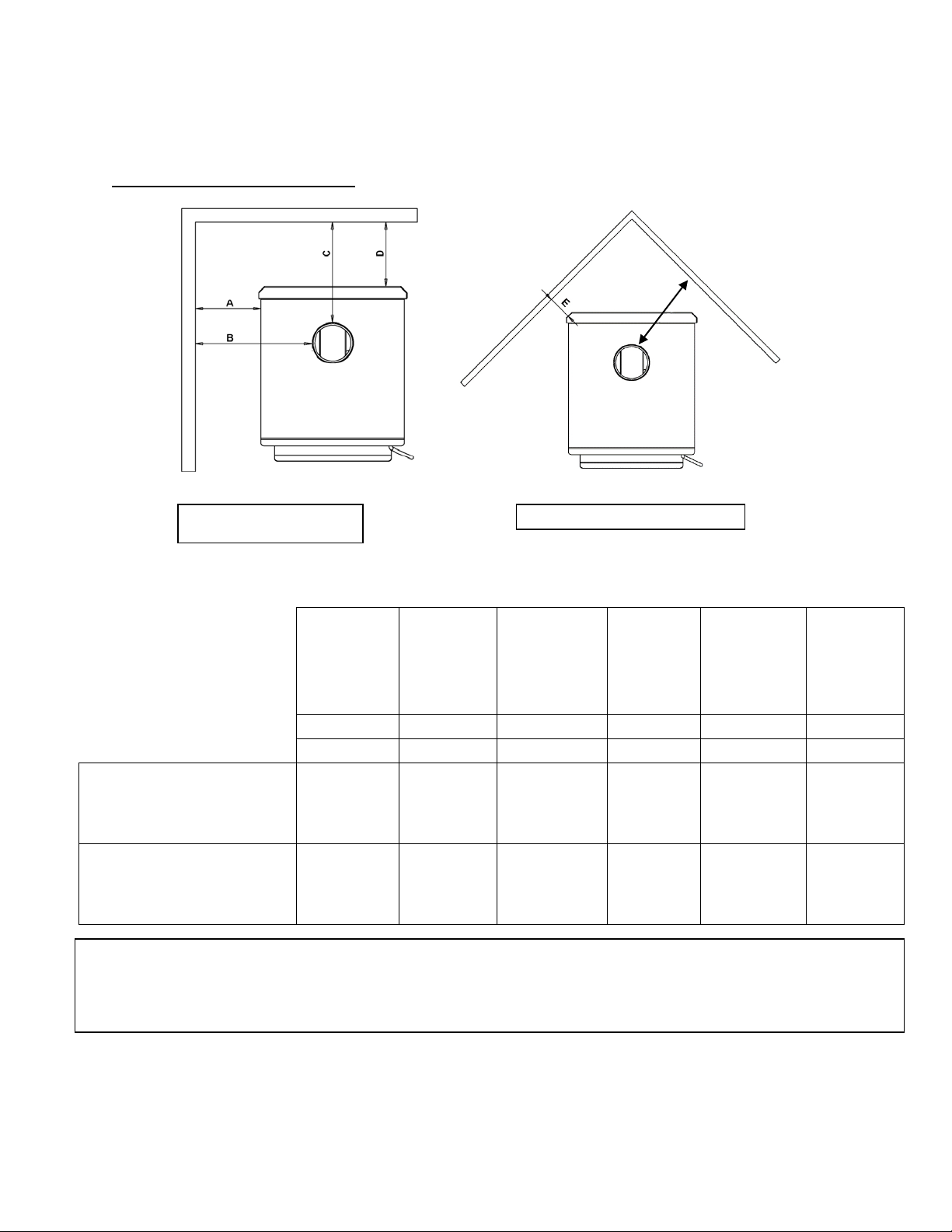
ADHERE to the 10-3-2 rule regarding
chimney terminations.
•
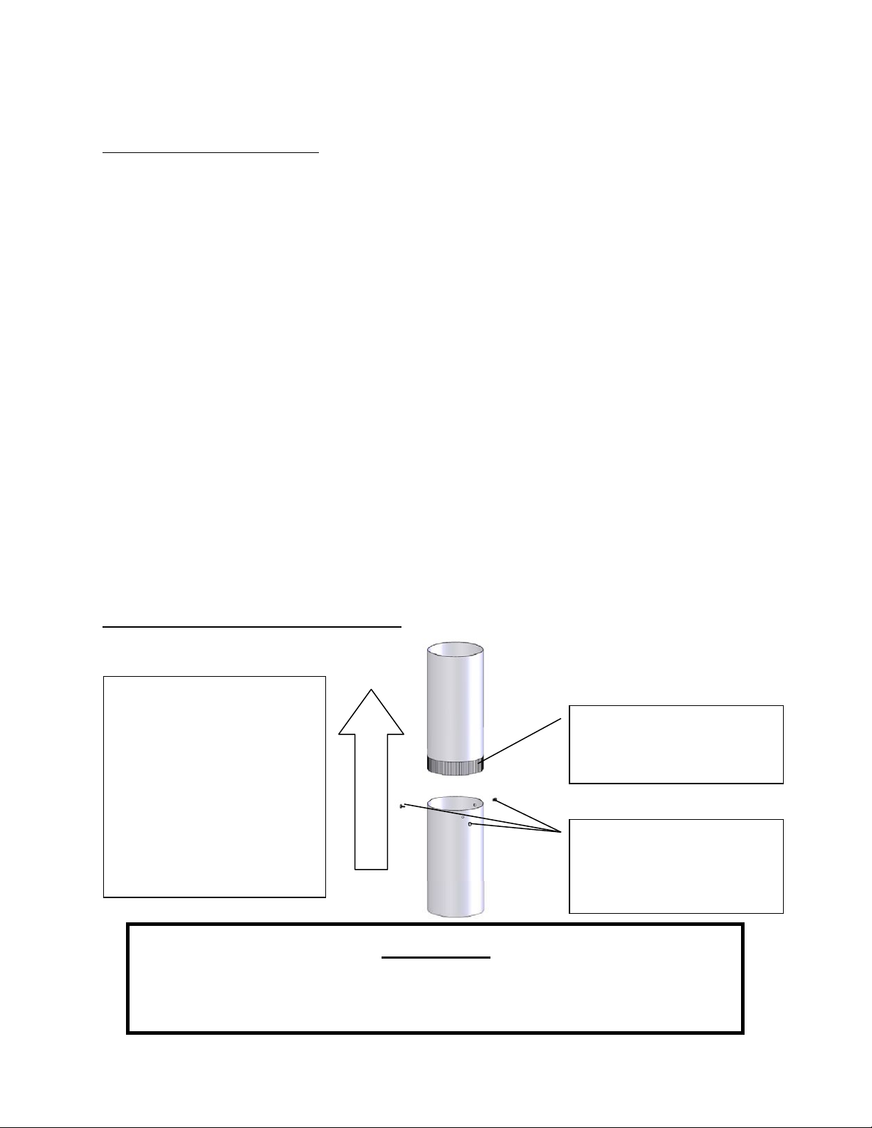
INSTALL single wall chimney
connector with the male end down
to prevent creosote leakage. Follow
double wall chimney connector
manufacturer’s instructions
regarding proper pipe installation.
WARNING: Venting system surfaces get HOT, and can cause burns if
touched. Noncombustible shielding or guards may be required.
Where passage through a wall or partition of combustible construction is desired, the
installation shall conform with CAN/CSA-B365.

Flue Gas Direction
AdditionalVenting Information
INSTALLATION
•
Do not mix and match components from different pipe manufacturers when assembling
your venting system (i.e. Do NOT use venting pipe from one manufacturer and a thimble
from another).
•
We require a minimum chimney height of 15.0 ft. Chimney systems shorter than this
may not create the amount of draft which is required to operate this wood burning unit.
•
Do not use makeshift compromises when installing the venting system; have existing
chimney systems inspected before use and be certain all new chimney systems are
installed to the manufacturer’s specifications and with only UL listed components (ULC if
Canada).
•
Prefabricated venting systems used for this stove must be listed to CAN/ULC S629
(Canada) and UL 103HT (US).
•
Never install a draft inducer or any other system which increases the natural draft of the
chimney; similarly, do not install a barometric or stovepipe damper with this unit.
•
Never use single wall or double chimney connector as a chimney system; never pass
either type of chimney connector through a combustible wall without carefully following
the manufacturer’s instructions and those listed in the following page on Wall Pass-
Throughs. NEVER pass chimney connector through an attic, floor, closet or roof.
•
Only use 24 gauge MSG black single wall chimney connector or UL Listed (ULC if Canada)
double wall chimney connector.
Single Wall Chimney Connector Installation
The male end of single wall
chimney connector is
installed facing down so that
any liquid creosote in the
flue will run into the unit
instead of onto the outside
of the pipe (the natural draft
in the chimney system will
prevent smoke leakage at
the joints).
Crimped or male end of
single wall chimney
connector must face down.
Fasten each single wall
chimney connector joint
with three sheet metal
screws.
WARNING
•
INSTALL VENT AT CLEARANCES SPECIFIED BY THE VENT MANUFACTURER.
•
HOT! Do not touch! Severe burns or clothing ignition may result.
•
Glass and other surfaces are hot during operation.

INSTALLATION
Wall Pass-Throughs
In Canada, the
installation
must
conform
to CAN/CSA-8365 when passing through
combustible
construction.


18.0 in.
2.0 ft.
3.0 ft.
INSTALLATION
Approved Venting Method 1: Through the Wall Factory Built Chimney
10
ft.
Termination Cap
Storm Collar
Roof Flashing
The 10-3-2 Rule: The chimney system
must terminate 3.0 ft. above the point
where its centerline passes through the
roof AND the chimney must terminate
2.0 ft. above any part of the dwelling
within a 10 ft. radius of the chimney.
Wall Thimble
Class A Chimney System
Chimney Connector
(Single or Double Wall)
Tee and Tee Support
•
Prefabricated chimney systems must conform to UL-103HT (2100 °F) for the U.S. and CAN/ULC-S629 (650°C) for
Canada.
•
This wood burning unit is only listed for installation with 6.0” diameter chimney connector and chimney systems.
Installing this unit on prefabricated chimneys larger than 6.0” diameter will result in decreased draft and the
potential for poor unit performance.
•
Follow all venting system manufacturer’s installation requirements and required clearances.
•
Use three sheet metal screws at each single wall chimney connector joint (check manufacturer’s
recommendations when double wall chimney connector is used).
•
Drill three holes in the flue collar of the unit and attach the chimney connector to the unit using sheet metal
screws (holes should be pre-drilled in flue collar from factory).
•
Properly attach the prefabricated chimney system to the home in strict accordance with the prefabricated
chimney system manufacturer’s instructions.
•
Avoid numerous elbows and excessive horizontal runs as both will lead to poor draft and increased creosote
accumulation. Horizontal runs of chimney connector must never exceed 4.0 ft. and the overall length of the
chimney connector must not exceed 8.0 ft. with single wall black connector pipe. If necessary to run longer
than 8.0 ft. of chimney connector pipe, double wall black chimney connector pipe must be used.
•
Special adapters and slip connectors are available to eliminate the need to cut single wall chimney connector.
Double wall chimney connector must be used with these slip connectors, as it cannot be trimmed to length.
Please Note: Installation diagrams are for reference purposes only and are not drawn to scale, nor meant to be used as plans
for each individual installation. Please follow all venting system requirements, maintain the required clearances to
combustibles, and follow all local codes.

2.0 ft.
3.0 ft.
INSTALLATION
Approved Venting Method 2: Through the Ceiling
10
ft.
Termination Cap
Storm Collar
The 10-3-2 Rule: The chimney system
must terminate 3.0 ft. above the point
where its centerline passes through the
roof AND the chimney must terminate
2.0 ft. above any part of the dwelling
within a 10 ft. radius of the chimney.
Roof Flashing Class A Chimney System
Ceiling Support Box
Chimney Connector
(Single or Double Wall)
•
Prefabricated chimney systems must conform to UL-103HT (2100 °F) for the U.S. and CAN/ULC-S629 (650°C) for
Canada.
•
This wood burning unit is only listed for installation with 6.0” diameter chimney connector and chimney systems.
Installing this unit on prefabricated chimneys larger than 6.0” diameter will result in decreased draft and the potential
for poor unit performance.
•
Follow all venting system manufacturer’s installation requirements and required clearances.
•
Use three sheet metal screws at each single wall chimney connector joint (check manufacturer’s
recommendations when double wall chimney connector is used).
•
Drill three holes in the flue collar of the unit and attach the chimney connector to the unit using sheet metal screws
(holes should be pre-drilled in flue collar from factory).
•
Properly attach the prefabricated chimney system to the home in strict accordance with the prefabricated chimney
system manufacturer’s instructions.
•
The overall length of the chimney connector must not exceed 8.0 ft. In the case of cathedral ceilings, the
prefabricated chimney system should extend to 8.0 ft. from the top of the unit if using single wall chimney
connector pipe. If necessary to run longer than 8.0 ft. of chimney connector pipe, double wall black chimney
connector pipe must be used.
•
Special adapters and slip connectors are available to eliminate the need to cut single wall chimney connector.
Double wall chimney connector must be used with these slip connectors, as it cannot be trimmed to length.
Please Note: Installation diagrams are for reference purposes only and are not drawn to scale, nor meant to be used as plans
for each individual installation. Please follow all venting system requirements, maintain the required clearances to
combustibles, and follow all local codes

2.0 ft.
18.0 in.
3.0 ft.
INSTALLATION
Approved Venting Method 3: Internal or External Masonry Chimney System
10
ft.
Chimney liner cross-sectional
area (Length x Width) must
be
no larger than twice the cross-
sectional area of the flue collar
(2 x 28.27 in2 = 56.55 in2). If
chimney liner is larger than
56.55 in2, relining with a 5.5”
or 6.0” liner is required
The 10-3-2 Rule: The chimney system
must terminate 3.0 ft. above the point
where its centerline passes through the
roof AND the chimney must terminate
2.0ft. above any part of the dwelling
within a 10 ft. radius of the chimney.
Chimney Connector
(Single or Double Wall)
Masonry Thimble with
proper clearance to
combustibles
Ash Cleanouts must
have an airtight seal to
prevent weak draft.
•
Follow the rules listed above concerning maximum permissible flue liner size; installing this unit on masonry chimneys
exceeding 56.55 in2 in cross-sectional area will result in decreased draft and the potential for poor unit performance.
•
Use three sheet metal screws at each single wall chimney connector joint (check manufacturer’s
recommendations when double wall chimney connector is used).
•
Drill three holes in the flue collar of the unit and attach the chimney connector to the unit using sheet metal
screws (holes should be pre-drilled in flue collar from factory).
•
Avoid numerous elbows and excessive horizontal runs as both will lead to poor draft and increased creosote
accumulation. Horizontal runs of chimney connector must never exceed 4.0 ft. and the overall length of the
chimney connector must not exceed 8.0 ft. with single wall black connector pipe. If necessary to run longer than
8.0 ft. of chimney connector pipe, double wall black chimney connector pipe must be used.
•
A tight seal at the thimble is crucial for proper unit performance and to create a safe installation. Use the proper
adapter designed for connecting single or double wall chimney connector to a masonry thimble.
•
Have existing masonry chimneys inspected for safety and proper clearances to combustibles before putting them into
service; a qualified chimney sweep can perform this inspection.
•
External masonry chimneys often suffer cold downdrafts and poor draft performance even when they meet the
cross-sectional area rules. In this case, a 6.0” insulated liner may be necessary.
Please Note: Installation diagrams are for reference purposes only and are not drawn to scale, nor meant to be used as plans
for each individual installation. Please follow all venting system requirements, maintain the required clearances to
combustibles, and follow all local codes.

INSTALLATION
INSTALLATION INTO A MASONRY FIREPLACE
Preparation
Keep in mind that this type of a installation will make it difficult to change speeds on the blower frequently. We
recommend picking a blower speed and sticking with it, since adjusting the blower will be difficult because of
the tight installation. WARNING: DO NOT ATTEMPT TO ADJUST BLOWER DURING OPERATION. SKIN
BURNS MAY OCCUR WHEN MAKING CONTACT WITH THE UNIT. WAIT FOR UNIT TO COMPLETELY
COOL BEFORE ATTEMPTING TO ADJUST BLOWER.
Measure your hearth to ensure it is large enough to accept the unit.
Unit must have a 36” clearance from the top of the stove to a mantel in accordance with NFPA 211.
For the USA: Hearth must extend at least
16 in. from the front of the fuel opening.
For Canada: Hearth must extend at least 18 in.
(450.0 mm) from the front of the fuel opening.
Inspect your hearth to be sure it is
constructed of a noncombustible material
such as brick or stone. Do not install this
stove on a hearth that is constructed of
wood framework that is covered by brick or
stone and do not install this unit in a zero (0)
clearance fireplace. The manufacturer will
not be held responsible for an accident
resulting from this stove being installed on a
hearth constructed of a combustible
material.
Inspect your fireplace to ensure it is in
proper working order and free of any
obstructions.
Prior to installation, remove the existing
damper or wire it to fasten it open.
Venting Your Stove - Direct Connect
When this unit is direct connected it will
require six inch (6”) diameter 24 gauge pipe
from the stove through the damper opening.
(NOTE: The chimney connector must be
attached to the appliance with a minimum
of three (3) screws, and 3 screws should
be used to attach each adjoining
section.)
We highly recommend having the chimney
fully lined with a 6 inch liner to ensure proper
draft. This will make it necessary to block off
the open area on both sides of the pipe that
passes through the damper opening, which
can be done with sheet metal or by packing
flame retardant fiberglass insulation in the
open areas (no paper or combustibles).
You must be sure the draft from the chimney
is being pulled through the stove, and not
around the connector pipe.
We highly recommend you have this
done by a professional. You should also contact your local authorities to be sure you are following all codes.
36 in. (91.4 cm) minimum
Stovetop to mantel
See hearth requirements
Remove or wire
damper open
6 in. (15.24 cm) liner
highly recommended
Connector
Pipe
The 10-3-2 Rule: The chimney system must terminate 3.0 ft.
above the point where its centerline passes through the roof
AND the chimney must terminate 2.0 ft. above any part of the
dwelling within a 10 ft. radius of the chimney.

INSTALLATION
WARNING
DO NOT INSTALL IN A SLEEPING ROOM.
CAUTION
THE STRUCTURAL INTEGRITY OF THE
MANUFACTURED HOME FLOOR, WALL
AND
CEILING/ROOF MUST BE
MAINTAINE
D.
Caution
NEVER draw outside combustion air
from:
Wall, floor or ceiling cavity
or
enclosed space such as an attic, garage or
crawl
space.
Mobile Home Installation (U.S. ONLY, NOT APPROVED FOR CANADIAN MOBILE HOME INSTALLATION)
•
The wood stove MUST be secured to the floor of the mobile home using lag bolts and the holes
provided in the bottom of the unit for this
purpose. Outdoor-aired space heaters
must be attached to the structure. Use a
#8 copper wire to ground stove to frame
of mobile home.
•
The wood stove must be connected to the
chimney system with double wall chimney
connector which is UL listed for use in
mobile and manufactured homes.
•
Carefully follow all clearances listed in the
appropriate section of this manual AND follow
the venting manufacturer’s
minimum
clearance
requirements. Similarly, be certain
the venting system used is approved
for mobile
home use.
•
Installation must be in accordance with
Manufacturers Home & Safety Standard
Chimney Cap/Spark Arrestor
Class A Chimney System
Roof Flashing and Storm Collar
Joist Shield/Firestop
Mobile Home Approved Double
Wall Chimney
Connector
Use silicone to create a vapor
barrier where the chimney passes
through to exterior.
(HUD) CFR 3280, Part 24 as well as any applicable local codes.
Outside CombustionAir
•
The use of outside combustion air is mandatory when installing this wood stove in a mobile or
manufactured home.
•
The outside air connection pipe protrudes from the bottom center of the stove; a kit is available
from Englander. designed for connecting this unit to outside combustion air. [Part No. AC-OAK3]
•
If it is not feasible to use the AC-OAK3 outside air hookup kit in your stove installation, other
materials may be used, provided the following rules are followed:
o The pipe used for outside air hookup must be metal, with a minimum thickness of .0209in.
(25 gauge mild steel) or greater and an inside diameter of approximately 2.75 in.
o Keep pipe runs short and use a mechanical fastener at each pipe joint.
o A screen or other protection device must be fitted over the outside air termination point to
prevent rain, debris and nuisance animals from entering the piping system. Inspect the
outside combustion air inlet for block and debris monthly.
REMOVE TO ALLOW
TRANSPORTATION

FLOOR PROTECTION
•
This wood stove requires a U.L. listed (ULC if Canada) floor protector with a R factor of no less than
1.0, if the stove is to be installed on a combustible floor. If the floor the stove is to be installed on
is already non-combustible (i.e. a concrete floor in a basement), no floor protection is needed
(although a decorative floor protector can still be used for aesthetic reasons).
•
When using any floor protector, consider that this stove is not only heavy but will induce heating
and cooling cycles on the floor protector which can damage tile and loosen mortar and grout joints
located near the stove.
•
The floor protector should be UL rated and listed, or equivalent (ULC if Canada1) and must be
noncombustible. A hearth rug is NOT an approved substitute for a proper hearth pad.
•
For the US: The floor protector must extend at least 16 in. from the front of the fuel opening, 8 in.
from the sides of the door opening and 8 in. from the rear of the unit.
•
For Canada: The floor protector must extend at least 450 mm from the front of the fuel
opening,
200 mm from the sides of the door opening and 200 mm from the rear of the unit.
•
The floor protector must extend 2 in. (50.8 mm.) on either side of any horizontal venting runs and
extend directly underneath any vertical venting pipe.
CAUTION
NEVER USE GASOLINE, GASOLINE-TYPE LANTERN FUEL, KEROSENE, CHARCOAL LIGHTER
FLUID,
OR SIMILAR LIQUIDS TO START OR “FRESHEN UP” A FIRE IN THIS HEATER. KEEP ALL
SUCH
LIQUIDS WELL AWAY FROM THE HEATER WHILE IN USE. ADDITIONALLY, NEVER APPLY
FIRE-
STARTER TO ANY HOT SURFACE OR EMBERS IN THE
STOVE.
1In Canada, to comply with CSA B365, Installation Code for Solid-Fuel-Burning Appliances and Equipment, any combustible covering beneath the appliance and/or
within the area extending horizontally at least 450 mm (18 in) beyond the appliance on any side equipped with a door, and at least 200 mm (8 in) beyond the appliance
on other sides, shall be protected by a continuous, durable, non-combustible pad that will ember protection. The 450 mm (18 in) ember protection required on any side
with a door shall extend for the full width of the appliance plus the 200 mm (8 in) required on each side of the appliance without a door. Where the appliance is
installed less than 200 mm (8 in) from a wall, the ember pad need only extend to the base of the wall. An ember pad shall not be placed on top of a carpet unless the
pad is structurally supported to prevent displacement and distortion.
38 ½ in
47 in
_____ in
____ in
A: US 8 in
CAN 8 in / 200 mm
B: US 16 in
CAN 18 in / 450 mm

First Fire‐ Remember to open a door
and/or window to ventilate the area.
You may find it necessary to open
several doors or windows for plenty
of ventilation.
OPERATION
Break-In Fires
•
This wood burning unit is constructed of heavy gauge
steel and cast iron and is built to last a long time.
However, in order to ensure no excessive thermal stresses are induced on the
metal during
the
first fire, three break-in fires should be burned, each one slightly hotter than the last. These
break-in fires will not only help the stove body acclimate to the high temperatures of the fire,
but will also slowly cure the high temperature stove paint, which will ensure the high
quality finish lasts for years.
•
This stove has a single air control rod which regulates the wood burn rate; when the primary air
control slide is pushed all the way into the unit, the stove will burn more slowly and put out
heat over a longer time period. Conversely, when the air control slide is pulled all the way out,
the unit will burn more quickly and put out a larger amount of heat over a relatively shorter
time
period. Do not attempt to modify the range of air control adjustment for any reason.
•
The first break-in fire should be just a large kindling fire, getting the stove to about 300°
. Once
this temperature has been reached, allow the fire to die out with the air control open. The
second and third break-in fires should be a bit larger, with some small dry splits added to the
kindling load. The temperature goal during these fires is about 350°F – 450°F; don’t let the fire
get hotter than that.
Continuous Operation – Daily Operation after your Break-In Fires
Start-up
-Load the firebox with wood, split to moderate size.
-On top of the startup wood, add dry kindling split into very small pieces.
-Ignite the kindling from the top until a flame is established.
-Close the door and set the damper to High (with rod pulled all the way out) to reduce the
amount of smoke.
High Burn
-Be sure the dog box is not covered with ashes or coals (see Brick Layout, page 34, for dog box
location).
-Load wood load onto the coal bed after chopping and packing coals, if necessary.
-Close the door, set the damper to High (with rod pulled all the way out) and set blower to High
speed.
Low Burn
-Be sure the dog box is not covered with ashes or coals (see Brick Layout, page 34, for dog box
location).
-Load wood load onto the coal bed after chopping and packing coals, if necessary.
-Close the door, set the damper to High and set blower to High speed.
-After 15 minutes, set the damper to Low (rod pushed all the way in) and set blower to Low speed.
Medium Burn
-Be sure the dog box is not covered with ashes or coals (see Brick Layout, page 34, for dog box
location).
-Load wood load onto the coal bed after chopping and packing coals, if necessary.
-Close the door, set the damper to ½ closed and set blower to High speed.
-After 15 minutes, set the blower to Low speed.

age | 18
OPERATION
•
The optional room air convection blower was designed to extract the maximum amount of heat
from the stove, for the highest possible heat transfer into the room. Since the blower is so
efficient at removing heat from the unit, it is very important to only operate the room air blower
after a fresh wood load has been allowed to burn for at least thirty (30) minutes. Allowing a fresh
load of wood to burn without the blower on ensures that the entire unit reaches proper
operation temperatures and that the secondary combustion system is functioning properly.
Additionally, follow the guidelines below for acceptable blower speeds.
•
When using the optional room air convection blower (Part No. AC-16, or you can upgrade to the
AC-30), the blower should be operated as follows depending on heat output level:
Burn
Rate
High
Medium High
Medium
Medium Low
Low
Blower Speed AC-16
High
High
Low
Low
Low
Blower Speed AC-30
High
Medium High
Medium
Medium Low
Low
Creosote –Formation and Need for
Removal
When wood is burned slowly, it produces tar and other organic vapors,
which
combine with expelled moisture to form creosote. The creosote
vapors
condense in the relatively cool chimney flue of a slow-burning fire. As a
result,
creosote residue accumulates on the flue lining. When ignited, this
creosote
makes an extremely hot fire. The chimney and chimney connector should
be
inspected at least once every two months during the heating season
to
determine if a creosote buildup has occurred. If creosote has accumulated,
it
should be removed to reduce the risk of chimney
fire.
DO NOT USE GRATES OR ANDIRONS OR OTHERWISE ELEVATE FIRE – BUILD
WOOD FIRE DIRECTLY ON
HEARTH
DO NOT OPERATE WITH THE MAIN DOOR OPEN – OPERATING THE STOVE WITH THE
MAIN
DOOR OPEN WILL CREATE AN OVER‐
FIRE
In the event of a creosote or soot fire (chimney fire), close the air control on the
stove,
contact the local fire department and get out! Do not throw water on the fire!
Contact
your local fire authority for more information on how to handle a chimney fire
and
P
develop a safe evacuation plan for you and your family in the event of a chimney fire.
This manual suits for next models
1
Table of contents
Other Englander Wood Stove manuals
Popular Wood Stove manuals by other brands

Enviro
Enviro 1200 Insert owner's manual

Regency Fireplace Products
Regency Fireplace Products F2404M Owners & installation manual

HearthStone
HearthStone Phoenix 8612 owner's manual

ACR STOVES
ACR STOVES FB5BK Technical manual

Contura
Contura C i4 FS installation instructions

Enerzone
Enerzone EB00060 Installation and operation manual

Bullerjan
Bullerjan B3 Keramik MAX Installation and operation manual

United States Stove Company
United States Stove Company Logwood 2421 owner's manual

Nordica
Nordica INSERTO 80 CRYSTAL EVO 2.0 user manual

Osburn
Osburn 1600 owner's manual

VEVOR
VEVOR WMCP07-1 user manual

HearthStone
HearthStone Heritage IV owner's manual