Englaon Wireless-DVR User manual
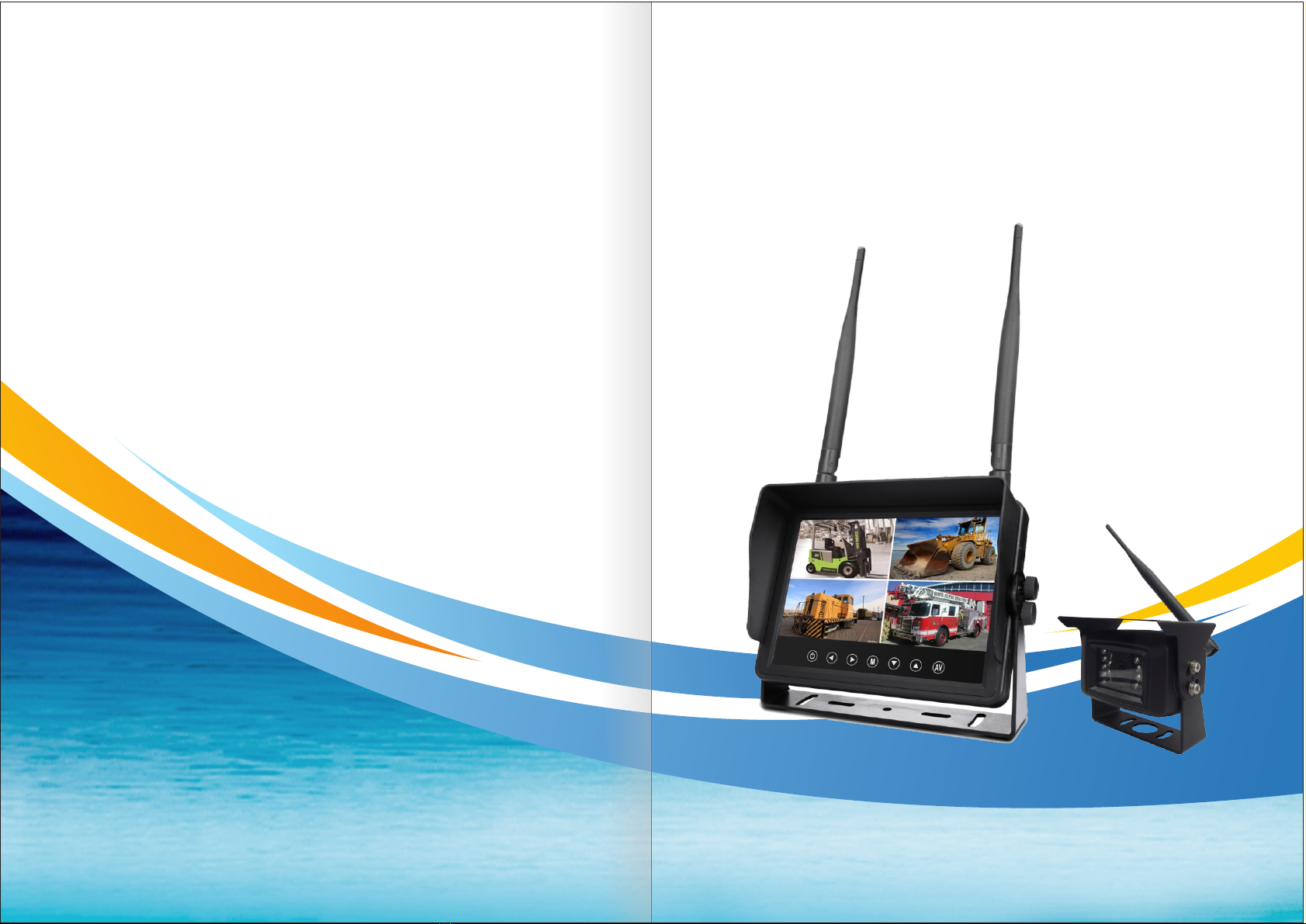
Waterproof Wireless Monitor
Operation Manual
1
Contents
.
2
Features/ Technical Specifications
.............................................................
3
Troubleshooting / OSD MENU Operation
..............................................................
4~8
Key/ Remote Instruction
9
Wiring Diagram .............................................................................................
10
.
Bracket Installation ..................................................................................
Contents/Preface .............................................................................................. 1
Preface
To ensure long-term trouble-free service of the products, please read this manual
carefully before using the product.
Notes:
1. Do not try to open the covers. It is a high precision product. Please close the
power in time if anomalies.
2. Do not use organic solvent clear the covers, to avoid it peel off painting.
3. Do not enforce to the lead wire., to avoid damage or poor connect.
4. Protect the product from fall down and shock.
5. Please wiring as diagram strictly, if wiring wrong will lead product can’t work
and even damage vehicle electrical system.
6. Do not use any affect operation of driving.
7. Do not let the product working at higher or lower than the suitable temperature
of machine.
Copyright protection:
This manual is the intellectual property of our company.
In order to continuously improve the products,
We reserve the right to change the specifications without prior notice.
10
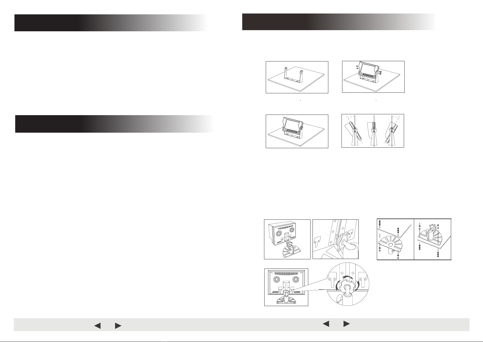
Bracket Installation
1. U-Bracket Installation
1) Use the screw fixed the U-bracket. Put the monitor into
the bracket, adjust angle and locking it.
2) Finished the installation. Adjust the angle forward 30°to backward 30°.
User can adjust a suitable angle by oneself.
2. Plastic/Metal Bracket Installation
1) Firstly fixed the bracket via the screws, the screws of the top need lock to
nut of under.
2) Secondly put the metal buckle piece on the top of the fan-shaped bracket
into the notch at the back of the monitor.
3) Move the bracket to the proper
location.
4) Screw down the nut of bracket,
until the monitor fastening.
.............................................

9
Wiring Diagram
Reversing Display:
When the green wire is activated, the monitor automatically
switches to CAM1
.
When the white wire is connected to the positive wire of the left turn
light , the monitor automatically switches to CAM2(left side camera)
when the left turn indicator is activated.
When the blue wire is connected to the positive wire of the right turn
light,the monito automatically switches to CAM3
(right side camera)
when the right turn indicator is activated.
When the brown wire is connected to the positive wire of back-up light,
the monitor
automatically switches to CAM4 (back up camera) when
the back
up light is turned on. The distancing grid will also be displayed.
When the yellow wire is connected to the positive wire, the monitor
automatically switches to quad or split display. Connection depends on the
application request.
DC12V~32V(Red)
Av2 Trigger wire (White)
GND(Black)
Av3 Trigger wire (Brown)
Av4 Trigger wire (Blue)
Four way video inputs:
Av1 Trigger wire (Green)
Quad Trigger wire (Yellow)
2
Keystroke Instruction
Remote Instruction
Power On Mode
Analog Increase Volume Down
Volume Up Analog Decrease
Menu CH 1 (Video)
CH 2 (Video) CH 3 (Video)
CH 4 (Video)
Up/Down
Enter key
Increase
Power switch Decrease Menu/Exit

8
Menu
3) COLOR-SYS: Press or to select COLOR
-
SYS, Press to enter,
Press or to select NTSC/PAL.
4) AUTO-DIM: Press or
to select AUTO-DIM. Press
to enter, and then
press or to select ON/OFF. When it is on, the monitor will automatically turn
darker when it is placed in dark environment for 5s.
5) P-Line: press
or
to select ELETRONIC DISTANCE LABEL.
to enter, and press
or
to select ON/OFF, to open or close the electronic
distance label. When it is on, the electronic distance label will be displayed in Back channel.
6) DELAYTIME: 1-20S, with the step time of 1s.
AV
AV
Press AV
Display Mode
CAM3
CAM1
CAM4
CAM1
CAM2
CAM1
CAM3
CAM2
CAM4
CAM2
CAM4
CAM3
CAM4
CAM1 CAM2
CAM3 CAM4
CAM1 CAM2 CAM3
CAM4
3
Features
1. TFT LCD monitor with wide angle view and high resolution display.
2. NORMAL, MIRROR, FLIP and MIR FLIP viewing available.
3. Split mode, auto scan mode and single display mode available.
4. Auto pairing: Auto
pairing happens when camera is activated.
5. Support 4channel composite and single
channel recording in AVI signal format.
6. Auto dim function available.
7.
Full-function remote control.
8.
4 wireless camera input.
9. Multiple video formats: PAL / NTSC.
10. Wide voltage input: 10
-
32V .
11. On-board speaker (Optional).
12.
Auto switch to the working channel when trigger is activated
LCD size
7"
Resolution
800 x 3 (RGB) x 480
Contrast
500:1
Brightness
400 cd/m²
Viewing Angle
U: 50 / D:
70, R/L: 70
Aspect Ratio
16:9
Channel
4 channels
Operating Frequency 2400
-
2483.5 MHz
Receiving
Sensitivity
-89 dBm
Decompression Form MPEG4
Transmit Output Power
17 dBm
Modulation
2.4G FSK/GFSK
Time Delay
120ms
Transmitting Distance 30 -120 M
IP Ip69
System Format PAL / NTSC
Power Supply DC 10 -32V
Power Consumption Max. 6W
Loudspeaker 1.5W/8Ω
Operating temperature -
20~+70ºC,RH90%
Storage temperature -
30~+80ºC,RH90%
Technical Specifications
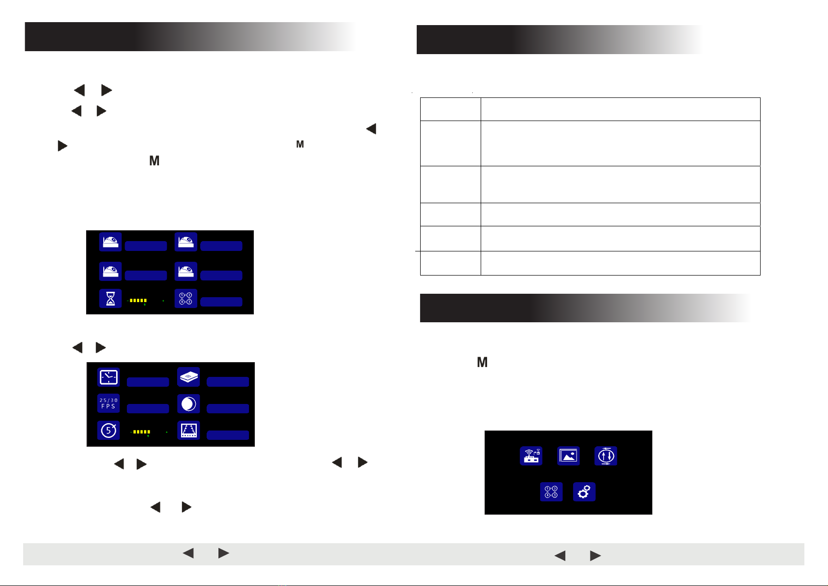
Press or to select SYSTEM,Press to enter
.
1) TIME
:
Press or
to select TIME, Press
to set. Press
or
for
selection decreasing or adding. Press
to continue the setting when finishing the
previous operation.
AV
AV
AV
(5)
2) LANGUAGE: Press or to select language, press to set.
AV
Chinese; English; French; German; Italian; Spanish; Portuguese; Russian; Korean;
Finnish; Dutch
7
Menu
Press or to select CAM1/CAM2/CAM3/CAM4/SCANTIME, and the
press to enter the setting accordingly. When the icons turn red, press
or on menu for selection decreasing or adding. Press to exit the menu.
At the submenu, press return to main menu.
If the channel is turned OFF, image of the corr
esponding camera will not be shown
in AUTOSCAN display mode.
Setting scale of SCANTIME is 5 -45S, with the step time of 5s.
AV
to select CAM-SETUP, and press AV to select
Press or .
(4)
ON OFF
CAM1
ON OFF
CAM2
ON OFF
CAM3
ON OFF
CAM4
ON OFF
Cam-Setup
2020/01/01
08:45:38
ENGLISH
NTSC PAL ON OFF
ON OFF
TIME LANGUAGE
COLOR-SYS AUTO-DIM
System
The symptoms described below do not necessarily mean a failure within the display.
Please check the following items before you initiate request for repair.
Symptoms Possible Causes/Solutions
No picture,
no sound
Improper connection of automobile adapter.
Use of unauthorized power supply.
Power switch is on OFF position.
No signal Check whether the camera has power supply.
Pair the monitor and the camera again.
No sound Check whether
the sound volume is turned off or set too low.
Dark picture Check whether brightness and contrast are adjusted correctly.
No color Adjust the HUE
settings.
Troubleshooting
4
Menu
●MENU
is allowed for operation under single image mode, not under quad view.
●Press to display the following options and settings:
1. Pairing 2. Picture
3. Mir - flip
4. Cam setup
5. System
PAIRING PICTURE MIR-FLIP
CAM-SETUP SYSTEM
6
Menu
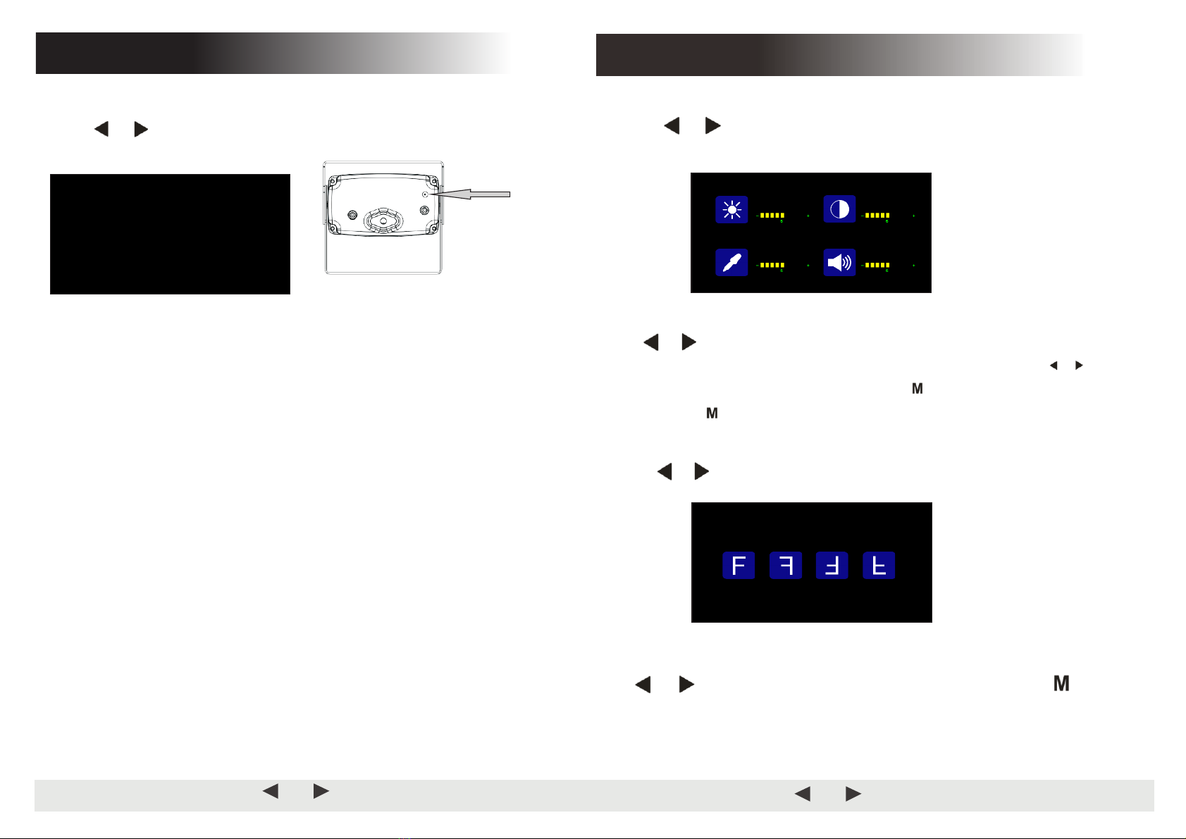
Press or to select PICTURE,and press to enter the submenu .
Press
or
to select BRIGHTNESS / CONTRACT / HUE / VOLUME,
and then
press
to enter the setting accordingly. When the icons turn red, press
or
on menu for selection
decreasing or adding. Press
to exit the menu. At the
submenu, press
return to main menu.
Press
or
to select MIRFLIP , and press
to select.
Press or to select NORMAL / MIRROR / MIRFLIP / FLIP . Press return
to main menu
AV
AV
AV
(2)
(3)
BRIGHTNESS CONTRAST
VOLUMEHUE
Picture
NORMAL MIRROR FLIP MIR-FLIP
MIR-FLIP
5
Press or to select PAIRING,then press to enter.
.
Auto pairing:
1. Choose the channel that needs to be set up, and the monitor display the message
“PAIRING START 50” and a counter that counts down 50s.
2. Within the countdown, power the camera.
3. The monitor and cameras will synchronize themselves with each other after the
camera is powered for 5s.
For successful auto pairing, the picture appears. If pairing is unsuccessful, the
monitor displays the message “No Signal”. Repeat the pairing procedure.
Manually pairing:
1. Choose the channel that needs to be set up, and the monitor display the message
“”
and a counter that counts down 50s.
2. Press the pairing button on the power-on camera.
3. The monitor and cameras will synchronize themselves with each other.
For successful auto pairing, the picture appears. If pairing is unsuccessful, the
monitor displays the message “No Signal”. Repeat the pairing procedure.
Hole
AV
(1)
PAIRING S TART
44
Pairing
Menu
PAIRING START 50
Table of contents


