ENHULK M1DP-XT-10 User manual

SYVIO TECHNOLOGY.CO.LIMITED
ROOM A,8/F,wok Cheung Building,635-637
Shanghai Street,Mong kok,Hong Kong
0086-133-2298-6467
service@enhulktools.com
Made in China
Compact Router
Please Read Carefully Before Use
Original Instruction Manual
M1DP-XT-10
(R0700)
M1DP-XT-10
(R0700+0701)

Safety Instruction
General Power Tool Safety
Save All Warnings And Inst-
ructions For Future Reference.
Read all safety warnings and all instructions.Failure
to follow the warnings and instructions may result in
electric shock, fire and/or serious injury.
The term "power tool" in the warnings refers to
your mains-operated (corded) power tool or battery
-operated (cordless) power tool.
Keep work area clean and well lit.Cluttered or dark
areas invite accidents.
1.
Do not operate power tools in explosive atmosph-
eres, such as in the presence of flammable liquids,
gases or dust.Power tools create sparks which may
ignite the dust or fumes.
2.
Keep children and bystanders away while opera-
ting a power tool.Distractions can cause you to
lose control.
3.
Power tool plugs must match the outlet. Never
modify the plug in any way. Do not use any adapter
plugs with earthed (grounded) power tools.Unmo-
dified plugs and matching outlets will reduce risk
of electric shock.
4.
Avoid body contact with earthed or grounded su-
rfaces such as pipes, radiators, ranges and refrig-
erators.There is an increased risk of electric shock
if your body is earthed or grounded.
5.
Do not expose power tools to rain or wet conditi-
ons.Water entering a power tool will increase the
risk of electric shock.
6.
Do not abuse the cord. Never use the cord for ca-
rrying, pulling or unplugging the power tool. Keep
cord away from heat, oil, sharp edges or moving
parts.Damaged or entangled cords increase the
risk of electric shock.
7.
When operating a power tool outdoors, use an e-
xtension cord suitable for outdoor use.Use of a
cord suitable for outdoor use reduces the risk of
electric shock.
8.
If operating a power tool in a damp location is
unavoidable, use a ground fault circuit interrup-
ter (GFCI) protected supply.Use of an GFCI reduces
the risk of electric shock.
9.
Work Area Safety
Electrical Safety
Do not force the power tool. Use the correct po-
wer tool for your application.The correct power
tool will do the job better and safer at the rate
for which it was designed.
18.
Do not use the power tool if the switch does not
turn it on and off.Any power tool that cannot be
controlled with the switch is dangerous and must
be repaired.
19.
Disconnect the plug from the power source and
/or the battery pack from the power tool before
making any adjustments, changing accessories,
or storing power tools.Such preventive safety
measures reduce the risk of starting the power
tool accidentally.
20.
Store idle power tools out of the reach of child-
ren and do not allow persons unfamiliar with
the power tool or these instructions to operate
the power tool.Power tools are dangerous in the
hands of untrained users.
21.
Maintain power tools. Check for misalignment
or binding of moving parts, breakage of parts
and any other condition that may affect the
power tool’s operation. If damaged, have the
power tool repaired before use.Many accidents
are caused by poorly maintained power tools.
22.
Keep cutting tools sharp and clean.Properly
maintained cutting tools with sharp cutting
edges are less likely to bind and are easier to
control.
23.
Power Tool Use And Care
Stay alert, watch what you are doing and use co-
mmon sense when operating a power tool. Do not
use a power tool while you are tired or under the
influence of drugs, alcohol or medication.A mom-
ent of inattention while operating power tools may
result in serious personal injury.
10.
Personal Safety
Warnings
Use personal protective equipment. Always wear
eye protection.Protective equipment such as
dust mask, non-skid safety shoes, hard hat, or
hearing protection used for appropriate condi-
tions will reduce personal injuries.
11.
Prevent unintentional starting. Ensure the switch
is in the off-position before connecting to power
source and/or battery pack, picking up or carry-
ing the tool.Carrying power tools with your finger
on the switch or energising power tools that have
the switch on invites accidents.
12.
Remove any adjusting key or wrench before tur-
ning the power tool on.A wrench or a key left att-
ached to a rotating part of the power tool may
result in personal injury.
13.
Do not overreach. Keep proper footing and bal-
ance at all times.This enables better control of
the power tool in unexpected situations.
14.
Dress properly. Do not wear loose clothing or je-
wellery. Keep your hair, clothing, and gloves away
from moving parts. Loose clothes, jewellery or long
hair can be caught in moving parts.
15.
If devices are provided for the connection of dust
extraction and collection facilities, ensure these
are connected and properly used.Use of dust co-
llection can reduce dust-related hazards.
16.
Do not let familiarity gained from frequent use of
tools allow you to become complacent and ignore
tool safety principles. A careless action can cause
severe injury within a fraction of a second.
17.
EN
1

Safety Instruction
Use the power tool, accessories and tool bits
etc. in accordance with these instructions, tak-
ing into account the working conditions and the
work to be performed.Use of the power tool for
operations different from those intended could
result in a hazardous situation.
24. 7.
Keep handles and grasping surfaces dry, clean
and free from oil and grease. Slippery handles
and grasping surfaces do not allow for safe ha-
ndling and control of the tool in unexpected
situations.
25.
Hold the tool firmly.
8. Keep hands away from rotating parts.
9. Make sure the bit is not contacting the workpi-
ece before the switch is turned on.
10. Before using the tool on an actual workpiece,
let it run for a while. Watch for vibration or wo-
bbling that could indicate improperly installed
bit.
11. Be careful of the bit rotating direction and the
feed direction.
12. Do not leave the tool running. Operate the tool
only when hand-held.
13. Always switch off and wait for the bit to come
to a complete stop before removing the tool
from workpiece.
14. Do not touch the bit immediately after oper-
ation; it may be extremely hot and could burn
your skin.
DO NOT let comfort or familiarity with product
(gained from repeated use) replace strict adhe-
rence to safety rules for the subject product.
Misuse or failure to follow the safety rules stated
in this instruction manual may cause serious per-
sonal injury.
15. Do not smear the tool base carelessly with thi-
nner, gasoline, oil or the like. They may cause
cracks in the tool base.
16. Use bits of the correct shank diameter suitable
for the speed of the tool.
17. Some material contains chemicals which may
be toxic. Take caution to prevent dust inhalation
and skin contact. Follow material supplier safety
data.
18. Always use the correct dust mask/respirator for
the material and application you are working with.
Table 1: Minimum gage for cord
2
Have your power tool serviced by a qualified re-
pair person using only identical replacement pa-
rts.This will ensure that the safety of the power
tool is maintained.
26.
27. Follow instruction for lubricating and changing
accessories.
28. Keep handles dry, clean and free from oil and
grease.
If the supply cord is damaged, it must be replaced
by the manufacturer , its service agent or similarly
persons in order to avoid a hazard.
USE PROPER EXTENSION CORD. Make sure your
extension cord is in good condition. When using
an extension cord, be sure to use one heavy en-
ough to carry the current your product will draw.
An undersized cord will cause a drop in line volt-
age resulting in loss of power and overheating.
Table 1 shows the correct size to use depending
on cord length and nameplate ampere rating.
If in doubt, use the next heavier gage. The small-
er the gage number, the heavier the cord.
29.
Service
Hold power tool by insulated gripping surfaces,
because the cutter may contact its own cord.
Cutting a "live" wire may make exposed metal
parts of the power tool "live" and shock the op-
erator.
1.
2. Use clamps or another practical way to secure
and support the workpiece to a stable platform.
Holding the work by your hand or against the
body leaves it unstable and may lead to loss of
control.
Wear hearing protection during extended peri-
od of operation.
3.
Handle the bits very carefully.4.
Check the bit carefully for cracks or damage
before operation. Replace cracked or damaged
bit immediately.
5.
Avoid cutting nails. Inspect for and remove all
nails from the workpiece before operation.
6.
Trimmer Safety Warnings
Warnings
AWG
Ampere Rating
More Than
0618
25ft. 50ft. 100ft. 150ft.
16 16
14
14
12
1214
16
16
12
18
16
14
10
12
16
6
10
12
Not More Than
Volts Total Length Of Cord In Feet
Not Recommended
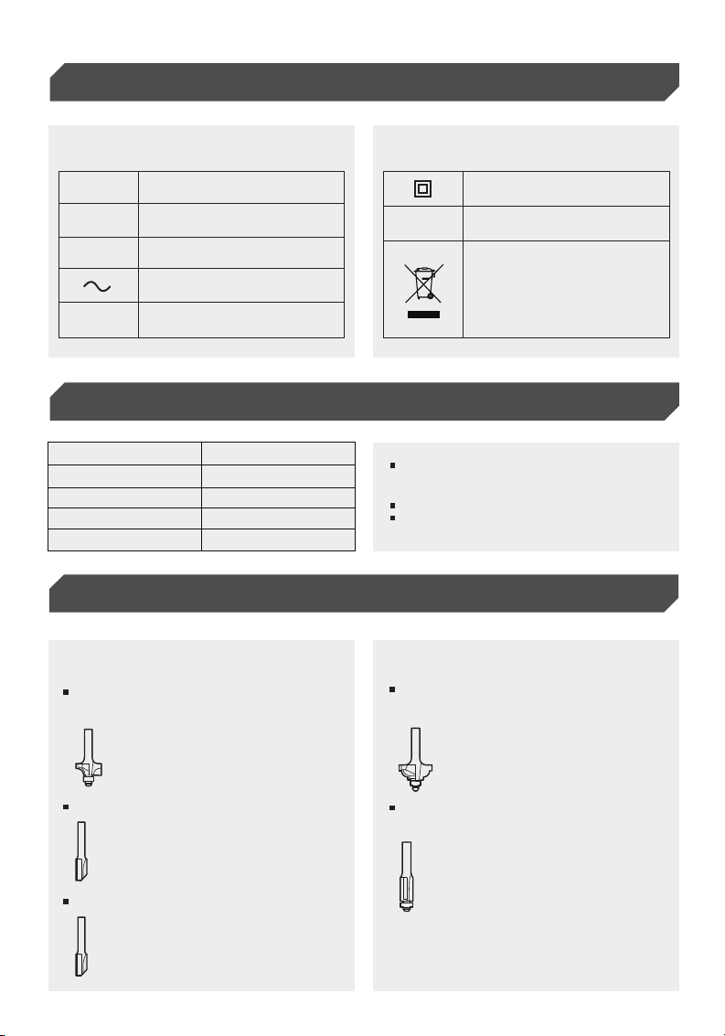
Symbols
Functional Description/Trimmer Bits
3
The followings show the symbols used for tool.
Waste electrical products must
not be disposed of with househ-
old waste. Please recycle where
facilities exist. Check with your
local authorities or retailer for
recycling advice.
Waste electrical products must
not be disposed of with househ-
old waste. Please recycle where
facilities exist. Check with your
local authorities or retailer for
recycling advice.
Technical Data
Due to our continuing programme of research and de-
velopment, the specificationsherein are subject to ch-
ange withoutnotice.
Specifications may differ from country to country.
Weight according to EPTA-Procedure 01/2003
VVolts
Amperes
Hertz
Alternating Current
No load Speed
Class II Construction
Revolutions Or Reciprocation
Per Minute
A
Hz
n
.../min
r/min
Model M1DP-XT-10
1/4’’,3/8’’
10,000~32,000/min.
200mm(7-7/8’’)
1.8(3.9Ibs)
Collet Chuck Capacity
No Load Speed
Overall Length
Net Weight
1/4" Ball bearing corner
rounding bit
1/4" Ball bearing cove
beading bit
3/8" Ball bearing flush
trmming bit
3/8" Straight bit
1/4" Straight bit
Trimmer Bits
M1DP-XT-10
(R0700)
M1DP-XT-10
(R0700+0701)
4
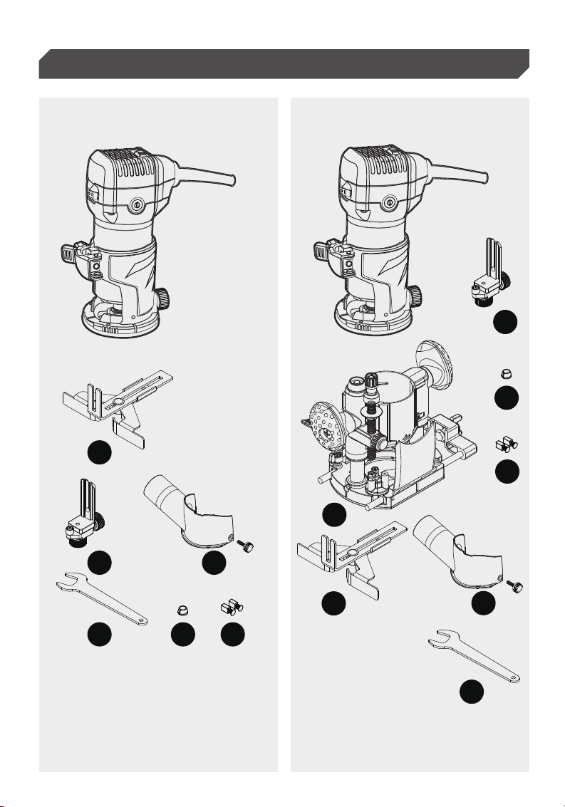
(A) Straight Guide Ruler
(B) Trimmer Guiding
(C) Transparent Cover
(D) Wrench
(E) 3/8" collet
(F) Carbon Brush
(A) Straight Guide Ruler
(B) Trimmer Guiding
(C) Transparent Cover
(D) Wrench
(E) 3/8" collet
(F)
(G)
Carbon Brush
Base
Functional Description
A
A
G
B
B
D
D
F
F
E
E
C
C

5
Electronic speed control for obtaining constant
speed.Possible to get fine finish, because the rot-
ating speed is kept constant even under load
condition.
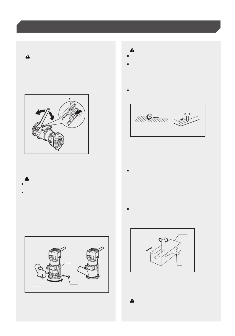
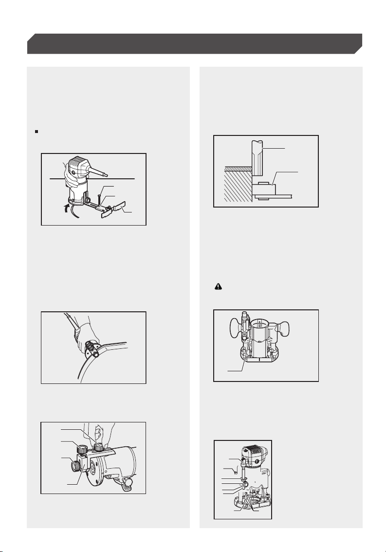
To adjust the bit protrusion, loosen the locking lever
and move the tool base up or down as desired by
turning the adjusting screw. After adjusting, tighten
the locking lever firmly to secure the tool base.
When the tool is not secured even if the locking lever
is tightened, tighten the hex nut and then tighten the
locking lever.
Before plugging in the tool, always check to see
that the tool is switched off.
To start the tool, press the "( I )" side of the switch.
To stop the tool, press the "(O)" side of the switch.
The tool equipped with electronic function are easy
to operate because of the following features.
1. Bit protrusion
1. Speed adjusting dial
2. Tool base
3. Scale
1. Switch
2. (O) side
3. ( I ) side
4. Locking lever
5. Adjusting screw
6. Hex nut
Always be sure that the tool is switched off and
unplugged before adjusting or checking function
on the tool.
Adjusting Bit Protrusion
Caution:
Note:
Switch Action
Electronic Function
Constant Speed Control
Speed Adjusting Dial
Soft-start feature minimizes start-up shock, and
makes the tool start smoothly.
Soft Start
Assembly
Functional Description
Caution:
Caution:
1
2
3
45
6
1
2 3
The tool speed can be changed by turning the
speed adjusting dial to a given number setting
from 1 to 6.
Higher speed is obtained when the dial is turned in
the direction of number 6. And lower speed is obta-
ined when it is turned in the direction of number 1.
If the tool is operated continuously at low speeds for
a long time, the motor will get overloaded, resulting
in tool malfunction.
The speed adjusting dial can be turned only as far
as 6 and back to 1. Do not force it past 6 or 1, or the
speed adjusting function may no longer work.
This allows the ideal speed to be selected for opti-
mum material processing, i.e. the speed can be
correctly adjusted to suit the material and bit
diameter.
Refer to the table for the relationship between the
number settings on the dial and the approximate
tool speed.
1
nimrebmuN
-1
1
2
3
4
5
6
10,000
32,000
12,000
17,000
22,000
27,000
6
Do not tighten the collet nut without inserting a bit,
or the collet cone will break.
Use only the wrenches provided with the tool.Insert
the bit all the way into the collet cone and tighten
the collet nut securely with the two wrenches or by
pressing the shaft lock and using the provided wre-
nch. To remove the bit, follow the installation proce-
dure in reverse.
1. Tighten
2. Loosen
3. Shaft Lock
1. Workpiece
2. Bit revolving direction
3. View from the top of the tool
4. Feed direction
1. Feed direction
2. Bit revolving direction
3. Workpiece
4. Straight guide
Always be sure that the tool is switched off and
unplugged before carrying out any work on the
tool.
Installing Or Removing Trimmer
Bit
For The Trimmer Base
Caution:
Assembly
Operation
Warnings
Warnings
Operating Instructions
Caution:
1
2
3
Before using the tool with the trimmer base, always
install the dust nozzle on the trimmer base.
Set the tool base on the workpiece to be cut without
the bit making any contact. Then turn the tool on
and wait until the bit attains full speed. Move the t
ool forward over the workpiece surface, keeping the
tool base flush and advancing smoothly until the
cutting is complete.
When doing edge cutting, the workpiece surface
should be on the left side of the bit in the feed
direction.
12
3
1. Dust nozzle
2. Thumb screw
3. Trimmer base
12
3
44
2
Moving the tool forward too fast may cause a poor
quality of cut, or damage to the bit or motor. Mov-
ing the tool forward too slowly may burn and mar
the cut.The proper feed rate will depend on the bit
size, the kind of workpiece and depth of cut. Before
beginning the cut on the actual workpiece, it is ad-
visable to make a sample cut on a piece of scrap
lumber. This will show exactly how the cut will look
as well as enable you to check dimensions.
When using the trimmer shoe, the straight guide or
the trimmer guide, be sure to keep it on the right
side in the feed direction. This will help to keep it
flush with the side of the workpiece.
Since excessive cutting may cause overload of the
motor or difficulty in controlling the tool, the depth
of cut should not be more than 3 mm at a pass when
Note:
1
23
4
7
cutting grooves. When you wish to cut grooves
more than 3 mm deep, make several passes with
progressively deeper bit settings.
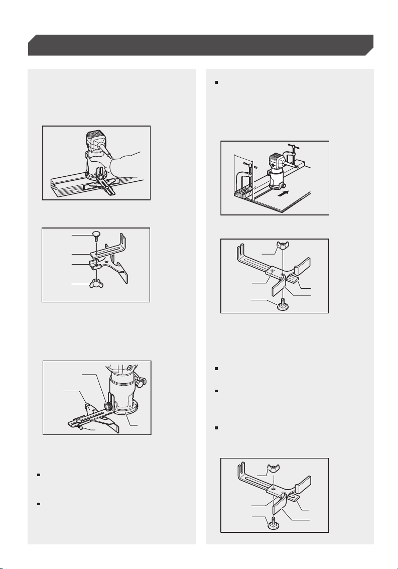
The straight guide is effectively used for straight
cuts when chamfering or grooving.
Attach the guide plate to the straight guide with
the bolt and the wing nut.
Straight Guide
Circular Work
Operating Instructions
If the distance (A) between the side of the workpiece
and the cutting position is too wide for the straight
guide, or if the side of the workpiece is not straight,
the straight guide cannot be used. In this case, firmly
clamp a straight board to the workpiece and use it
as a guide against the trimmer base. Feed the tool
in the direction of the arrow.
1. Bolt
2. Guide plate
3. Straight guide
4. Wing nut
1. Wing nut
2. Guide plate
3. Straight guide
4. Center hole
5. Bolt
Attach the straight guide with the clamp screw (A).
Loosen the wing nut on the straight guide and adjust
the distance between the bit and the straight guide.
At the desired distance, tighten the wing nut securely.
When cutting, move the tool with the straight guide
flush with the side of the workpiece.
1. Clamp screw (A)
2. Straight guide
3. Wing nut
4. Base
1
2
3
4
1
2
34
Min. and max. radius of circles to be cut (distance
between the center of circle and the center of bit)
are as follows:
Min.: 70 mm
Max.: 221 mm
For cutting circles between 70 mm and 121 mm in
radius. For cutting circles between 121 mm and 221
mm in radius.
Circular work may be accomplished if you assemble
the straight guide and guide plate as shown in the
figures.
A
1
2
3
4
5
1
2
3
4
5
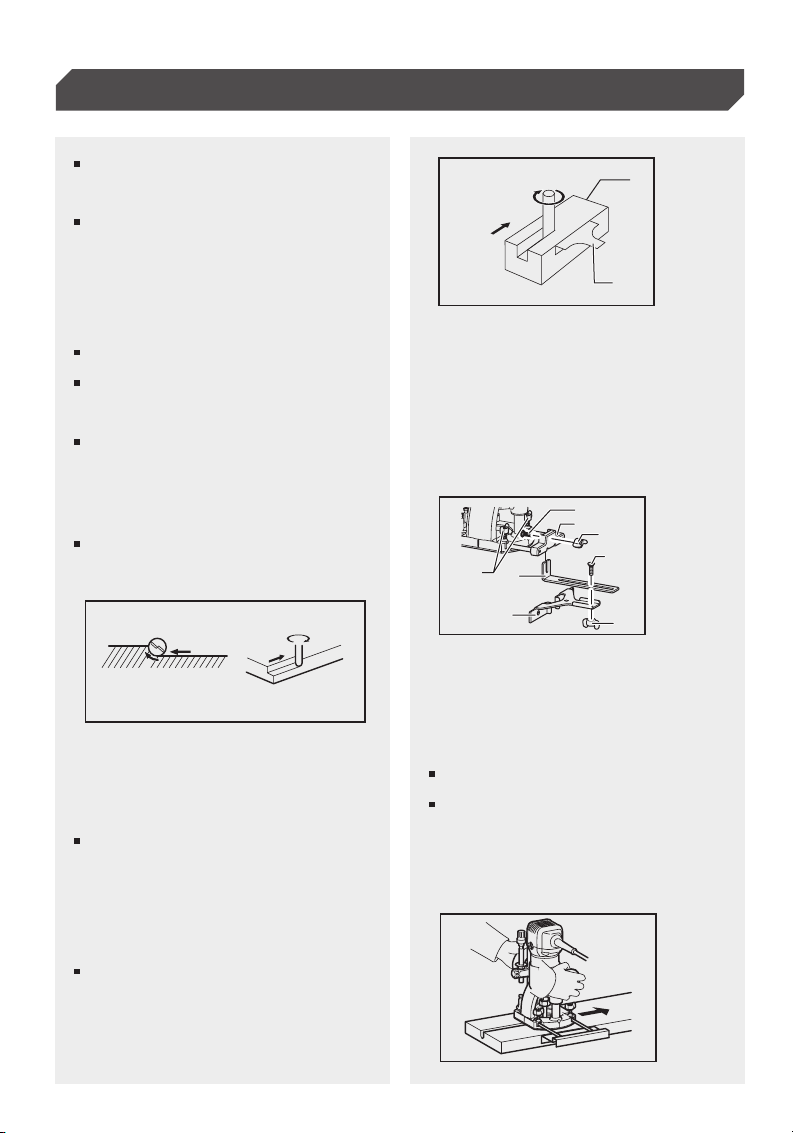
Align the center hole in the straight guide with the
center of the circle to be cut. Drive a nail less than
6 mm in diameter into the center hole to secure the
straight guide.Pivot the tool around the nail in clock-
wise direction.
Trimming, curved cuts in veneers for furniture and
the like can be done easily with the trimmer guide.
The guide roller rides the curve and assures a fine
cut.
Operating Instructions
1. Nail
2. Center hole
3. Straight guide
4. Center hole
1. Clamp screw (A)
2. Adjusting screw
3. Clamp screw (B)
5. Bolt
1. Adjusting knob
2. Lock lever
3. Depth pointer
4. Stopper pole setting nut
5. Fast-feed button
6. Stopper pole
7. Stopper block
8. Adjusting bolt
1. Workpiece
1. Plunge base
4. Trimmer guide
2. Bit
3. Guide roller
Install the trimmer guide on the tool base with the
clamp screw (A). Loosen the clamp screw (B) and
adjust the distance between the bit and the trimmer
guide by turning the adjusting screw (1 mm per turn).
At the desired distance, tighten the clamp screw (B)
to secure the trimmer guide in place.
When cutting, move the tool with the guide roller
riding the side of the workpiece.
When using as a router, hold the tool firmly with
both hands.
To use the tool as a router, install the tool on a
plunge base by pressing it down fully.
Trimmer Guide
When Using As A Router Only
With A Plunge Base
Adjusting The Depth Of Cut
When Using The Plunge Base
Circles between 172 mm and 186 mm in radius cannot
be cut using this guide.
Note:
1
2
3
1
2
3
4
1
2
3
Caution:
1
1
2
3
4
5
6
78
8
1. Wing nut
2. Guide plate
3. Straight guide
Operating Instructions
1. Feed direction
2. Bit revolving direction
3. Workpiece
4. Straight guide
Place the tool on a flat surface. Loosen the lock
lever and lower the tool body until the bit just
touches the flat surface. Tighten the lock lever
to lock the tool body.
Turn the stopper pole setting nut counterclockwise.
Lower the stopper pole until it makes contact with
the adjusting bolt. Align the depth pointer with the
"0" graduation. The depth of cut is indicated on the
scale by the depth pointer.While pressing the fast-
feed button, raise the stopper pole until the desired
depth of cut is obtained. Minute depth adjustments
can be obtained by turning the adjusting knob
(1 mm per turn).
By turning the stopper pole setting nut clockwise,
you can fasten the stopper pole firmly.
When doing edge cutting, the workpiece surface
should be on the left side of the bit in the feed
direction.
Now, your predetermined depth of cut can be obta-
ined by loosening the lock lever and then lowering
the tool body until the stopper pole makes contact
with the adjusting hex bolt of the stopper block.
Always firmly hold the tool by both grip during ope-
ration.Set the tool base on the workpiece to be cut
without the bit making any contact. Then turn the
tool on and wait until the bit attains full speed. Low-
er the tool body and move the tool forward over the
workpiece surface,keeping the tool base flush and
advancing smoothly until the cutting is complete.
The straight guide is effectively used for straight
cuts when chamfering or grooving.
1. Workpiece
2. Bit revolving direction
3. View from the top of the tool
4. Feed direction
1. Bolt
2. Guide holder
3. Wing nut
4. Bolt
5. Wing nut
6. Guide plate
7. Straight guide
8. Wing bolts
Straight Guide When Using As
A Router (Neededto Use With
Guide Holder
Straight Guide
Moving the tool forward too fast may cause a poor
quality of cut, or damage to the bit or motor. Moving
the tool forward too slowly may burn and mar the
cut.The proper feed rate will depend on the bit size,
the kind of workpiece and depth of cut. Before beg-
inning the cut on the actual workpiece, it is advis-
able to make a sample cut on a piece of scrap lum-
ber. This will show exactly how the cut will look as
well as enable you to check dimensions.
When using the straight guide, be sure to install it
on the right side in the feed direction. This will help
to keep it flush with the side of the workpiece.
Install the straight guide on the guide holder (optional
accessory) with the wing nut.
Insert the guide holder into the holes in the plunge
base and tighten the wing bolts. To adjust the dist-
ance between the bit and the straight guide, loosen
the wing nut. At the desired distance, tighten the
wing nut to secure the straight guide in place.
Note:
12
3
44
2
1
23
4
1
2
3
4
5
6
7
8
9

Always be sure that the tool is switched off and
unplugged before attempting to perform inspection
or maintenance.
Caution:
Operating Instructions
Maintenance
1. Guide bar
1. Limit mark
1. Screwdriver
2. Brush holder cap
2. Wing bolt
3. Straight guide
The straight guide is effectively used for straight
cuts when chamfering or grooving.
Never use gasoline, benzine, thinner, alcohol or the
like. Discoloration, deformation or cracks may result.
Always disassemble this base after use to clean
and store . And store the base separately .
Remove and check the carbon brushes regularly.
Replace when they wear down to the limit mark.
Keep the carbon brushes clean and free to slip in the
holders.
Both carbon brushes should be replaced at the
same time. Use only identical carbon brushes.
Use a screwdriver to remove the brush holder caps.
Take out the worn carbon brushes, insert the new
ones and secure the brush holder caps.
To install the straight guide, insert the guide bars i
nto the holes in the plunge base. Adjust the distance
between the bit and the straight guide. At the desir-
ed distance, tighten the wing bolts to secure the
straight guide in place.
When cutting, move the tool with the straight guide
flush with the side of the workpiece.
Replacing Carbon Brushes
Note:
123
If the distance (A) between the side of the workpiece
and the cutting position is too wide for the straight
guide, or if the side of the workpiece is not straight,
the straight guide cannot be used. In this case, firmly
clamp a straight board to the workpiece and use it
as a guide against the router base. Feed the tool in
the direction of the arrow.
A
1
1
2
10

Troubleshooting
Guarantee
11
Dear Customer,
Guarantee Guarantee Period And
Statutory Claims For Defects
This equipment is provided with a 2-year guarantee
from the date of purchase. In case of defects, you
have statutory rights against the seller of the
product. These statutory rights are not restricted by
our guarantee presented below. Terms of Guarantee
the term of the guarantee begins on the date of
purchase, please retain the original receipt and it’s
required as proof of purchase. If a material or
manufacturing defect occurs within 2-year of the
date of the purchasing, we will repair or replace the
product for you free of charge. This guarantee
requires the defective equipment and proof of
purchase to be presented within the 2-year period
with a brief written description of what constitutes
the defect and when it occurred. If the defect is
covered by our guarantee, you will receive either the
repaired product or a new product. No new
guarantee period begins on repair or replacement of
the product.
The guarantee period is not extended by the
guarantee service. This also applies for replaced or
repaired parts. Any damages and defects already
present at the time of purchase must be reported
immediately after unpacking.
Problem
Tool can't start
Tool can't start or big
spark when start the
tool
Bit install to collet,but
can't tight
Bit can't install to collet
Lock pin can't lock into
the lock spindle
Smell of burning or
smoking when using
tool
Bit is not stable after
installed
The tool won't lock up
in the base
The wood turned black
when the trimming
wood
Possible casues
Check the size of collet and bit(Metric
or British )
Change new bit or reduce force
Change a new carbon brush
Use an extra wrench to lock the spindle
Send to maintenance deparmet to
check and service
The size of collet and bit not match.
Carbon brush was broken or use up
Check the plug contect is ok or not/Check
the switch is OFF(O) or ON(I)/the power
socksocket is switch on or not.
Worn in collet/have something in collet
/Bit was not properly installed
Lock nut loose/Long-term over-locking,
resulting in locking fatigue
The lock pin may slightly change position,
not match with its original position after
long time use
The size of collet and bit not match. Change the collet or bit
Replug /Press the "ON ( I )" side of the
switch/switch on the power
Change new collet/Clean collet/Disass-
emble and reinstall bit
Tighten the lock nut a little
Motor has problem/something into the
motor house
The bit is blunt or over force on hand
Remedy
This manual suits for next models
2
Table of contents
Popular Wood Router manuals by other brands


Hitachi Koki
Hitachi Koki M 12V2 Handling instructions

Festool
Festool MFK 700 EQ Original instructions

Bosch
Bosch 1608LX instruction manual

Craftsman
Craftsman 315.269211 Operator's manual

Ergo tools
Ergo tools Pattfield E-OF 1200 operating instructions

CMT ORANGE TOOLS
CMT ORANGE TOOLS BTS-001 owner's manual