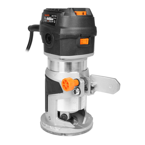
Bosch 1608LX User manual

Before use - Read this instruction manual.
Lisez attentivement la présente notice avant l'emploi.
Lea estas instrucciones de manejo antes de la utilización del aparato.
BM 2610909755 7/01 7/26/01, 12:03 PM1

2
7
6
5
84
3
2
1
9
Fig. 1
(Model 1608LX Pictured)
(Modèle 1608LX illustré)
(Modelo 1608LX ilustrado)
BM 2610909755 7/01 7/26/01, 12:03 PM2

3
Trim Router Components
1. Ventilation openings
2. Wrench slot
3. Slide "ON/OFF" switch
4. Motor clamping ring
5. Collet nut
6. Base assembly
7. Sub-base
8. Clamping ring screw
9. Trim guide assembly
10. Locking knob - depth of cut
11. Adjusting screw - depth of cut
12. Adjusting knob - trim guide
13. Locking screw - trim guide
14. Combination Wrench
15. Toothed Belt Pulley
16. Offset Base Assembly
17. Toothed Belt
18. Depth Locking Screw
19. Slotted Adjusting Gear
20. Wing Nuts
(NOTE: components not illustrated on page 2 are illustrated elsewhere in this manual)
1608M 1608 1608LX 1608T 1608U 1609A 1609AK
1609AKX
Steel Case * *
650 Watt Trim Motor * * * * * * * *
Wrench 2pcs 2pcs 2pcs 2pcs 2pcs 1pc 2pcs 2pcs
Trimmer Base * * * *
Laminate Trim Guide *
Deluxe Laminate * *
Trim Guide
Tilt Base * * *
Offset Base * * *
Underscribe Base * *
4mm Hex Key * * * *
3mm Hex Key * *
1/4 Collet * * * * * * *
Collet Nut * * * * * * *
Carbide Tipped Bit * *
Toothed Belt Pulley * * *
Product Data - Trim Router
Base dimensions 3.7" x 2.8" (95mm x 71mm)
Collet capacity 1/4" max.
Bit diameter 1" max.
(NOTE: This tool is designed for use with alternating current (AC) only.)
Accessory Listing
*STANDARD EQUIPMENT—ALL MODELS
BM 2610909755 7/01 7/26/01, 12:03 PM3

4
WARNING!“READALLINSTRUCTIONS”.
Failure to follow the SAFETY RULES identi-
fied by the BULLET (•) symbols listed BE-
LOW and other safety precautions, may result
inseriouspersonalinjury.Keeptheseoperating
instructions with this product.
GENERAL SAFETY RULES
for all Power Tools
Work Area
• KEEP WORK AREAS CLEAN. Cluttered
areas and benches invite accidents.
• AVOID DANGEROUS ENVIRONMENT.
Don’tuse powertoolsin damporwet locations.
Do not expose power tools to rain. Keep work
area well lit.
• AVOIDGASEOUSAREAS.Donotoperate
portableelectrictoolsinexplosiveatmospheres
in presence of flammable liquids or gases. Mo-
torsinthesetoolsnormallyspark,andthesparks
might ignite fumes.
• KEEP CHILDREN AWAY. Do not let visi-
tors contact tool or extension cord. All visitors
should be kept away from work areas.
Personal Safety
• GUARD AGAINST ELECTRIC SHOCK.
Prevent body contact with grounded surfaces
such as pipes, radiators, ranges and refrigerator
enclosures. Rubber gloves and non-skid foot-
weararerecommendedwhenworkingoutdoors,
wheredamporwetgroundmaybeencountered.
A Ground Fault Circuit Interrupter protected
power line must be used for these conditions.
• DRESS PROPERLY. Do not wear loose
clothing or jewelry. They can be caught in
moving parts. Wear protective hair covering to
contain long hair.
• USE SAFETY EQUIPMENT. WEAR
SAFETY GOGGLES or glasses with side
shields. Wear hearing protection during ex-
tended use of power tools and dust mask for
dusty operations.
• STAY ALERT. USE COMMON SENSE.
Watch what you are doing. Do not operate tool
when you are tired or under influence of drugs.
• REMOVE ADJUSTING KEYS AND
WRENCHES. Form habit of checking to see
that keys and adjusting wrenches are removed
from tool before turning it on.
• AVOIDACCIDENTALSTARTING.Don’t
carry plugged in tool with finger on switch. Be
sure the switch is OFF before being plugged in.
• DON’T OVERREACH. Keep proper foot-
ing and balance at all times.
• BEFORE CONNECTING THE TOOL to a
power supply (receptacle, outlet, etc.) be sure
the voltage supplied is the same as that speci-
fied on the tool’s nameplate. A power supply
with voltage greater than that specified for the
tool can result in serious injury to the user—as
wellas damagetothe tool.Ifin doubt,DONOT
PLUG IN THE TOOL. Using a power supply
with voltage less than the nameplate rating is
harmful to the motor.
“VoltsAC”designatedtoolsareforAlternating
Current 50-60 Hz only. “Volts DC” designated
tools are for Direct Current. Do not use AC
designatedtoolswithDCpowersupply.Donot
use electronic speed controlled tools with DC
power supply.
Tool Use and Care
•DON’T FORCE TOOL. It will do the job
better and safer at the rate for which it was
designed.
•USE RIGHT TOOL. Don’t force small tool
orattachment todothe jobofa heavy-dutytool.
Don’t use tool for purpose not intended—for
example; don’t use a circular saw for cutting
tree limbs or logs.
•SECURE WORK. Use clamps or a vise to
hold work. It’s safer than using your hand and
it frees both hands to operate the tool.
•DON’TABUSE CORD. Never carrytool by
cord or yank it to disconnect from receptacle.
Keep cord from heat, oil, and sharp edges.
Alwayskeepcordawayfromthespinningblade,
bitsoranyother moving partwhilethetoolisin
use.
•OUTDOOR USE EXTENSION CORDS.
When tool is used outdoors, use only extension
cordssuitableforuseoutdoorsandmarkedwith
suffix W-A (for UL), or W (for CSA). Refer to
section“ExtensionCords”,for proper corduse.
•DISCONNECT TOOLS. When not in use,
beforeservicing,orwhenchangingblades,bits,
cutters, etc.
•STORE IDLE TOOLS. When not in use,
tools should be stored in dry, high or locked up
place - out of the reach of children.
•DONOTALTERORMISUSETOOL.These
tools are precision built. Any alterations or
modifications not specified is misuse and may
result in a dangerous condition.
•THE USE OF ANY ACCESSORIES not
specified in this manual may create a hazard.
•MAINTAIN TOOLS WITH CARE. Keep
toolssharpandcleanforbetterandsaferperfor-
mance. Follow instructions for lubricating and
changing accessories. Inspect tool cords peri-
odically and if damaged, have repaired by au-
BM 2610909755 7/01 7/26/01, 12:03 PM4

5
thorizedservicefacility.Inspectextensioncords
periodically and replace if damaged. Keep
handlesdry,cleanandfreefrom oil and grease.
•CHECK DAMAGED PARTS. Before fur-
ther use of the tool, a guard or other part that is
damaged should be carefully checked to deter-
mine that it will operate properly and perform
its intended function. Check for alignment of
moving parts, binding of moving parts, break-
age of parts, mounting, and any other condi-
tions that may affect its operation. A guard or
other part that is damaged should be promptly
and properly repaired or replaced. Have defec-
tiveswitchesreplaced.Donotusetoolifswitch
does not turn it on or off.
•ALL REPAIRS, ELECTRICAL OR ME-
CHANICAL, should be attempted only by
trained repairmen. Contact the nearest Bosch
Factory Service Center, or Bosch Authorized
Service Center or other competent repair cen-
ter. Use only Bosch replacement parts, any
other may create a hazard
Safety Rules for Trim Router
•Alwayswear safetygoggles.Iftrimmerhas a
removablechip deflector, keep itin place when
routing.
•Never use dull or damaged bits. Handle bits
with care.
•Alwaysmakesuretheworkpieceisfreefrom
nails and other foreign objects which can cause
the bit and trimmer to jump and damage the bit.
•Be sure that the bit is installed according to
the procedure described in this manual. Check
all settings and adjustments before making a
cut. An incorrectly installed bit or loose setting
could cause an accident or injury. Always dis-
connect the power cord before making adjust-
ments or changing bits.
•Do not make adjustments while the tool is
running.
•Neverholdtheworkpieceinonehandandthe
trimmerinotherwheninuse.Alwaysclampthe
material and hold the trimmer securely with
both hands.
•Never start the trimmer when the bit is en-
gaged in the material. The bit’s cutting edge
may grab the material causing the trimmer to
get out of control. Always hold the trimmer
with two hands during start-up. The reaction
torque of the motor can cause the trimmer to
twist.
•When turning the trimmer "ON", be aware
that the bit is protruding below the base. Keep
hands away from this area.
•Do not cut or rout into existing walls, around
any fixture or in a blind area which may have
electrical wiring, as the bit could conduct elec-
tricity to the tool, creating a hazard for the
operator.
•The trimmer should always be used with its
base flat on the material being cut. For better
control and accuracy of cut, guide the trimmer
withboth hands. Use hand positions most com-
fortable and giving best control for your job.
•Never use bits that have a cutting diameter
greater than the opening in the base.
•The direction of feeding the trimmer into
the material is very important and it relates to
the direction of bit rotation. When viewing the
trimmer from the top, the bit rotates clockwise.
Whenthetrimmerislocatedbetweenyourbody
and the material, the feed direction must be to
theright.Ifthematerialislocatedbetweenyour
body and the trimmer, then the feed direction
must be to the left. Feeding the trimmer in the
wrong direction causes the cutting edge of the
bitto climboutoftheworkandpullthe trimmer
in the direction of this feed.
•Never touch the bit or other moving part
during use. After use the bit is too hot to be
touched by bare hands.
•Be sure that the bit has come to a complete
stopbefore youputthe trimmerdown.Thiswill
reducethechance of unintentional contact with
the bit.
•When using the tool for laminate trimming,
keep the laminate overhang small. Do no allow
too much laminate to overhang when cutting
thelaminateparts tosize.Whentheoverhang is
toogreat,it makesthetrimmermore difficultto
control. If the laminate overhangs the
workpiece by more than 2", use an overhang
bit to reduce the amount of material before
actuallytrimming the laminate todesiredsize.
WARNING! Some dust created by power
sanding, sawing, grinding, drilling, and other
construction activities contains chemicals
known to cause
cancer,birthdefectsorotherreproductiveharm.
Some examples of these
chemicals are:
•Lead from lead-based paints,
•Crystalline silica from bricks and cement and
other masonry products, and
•Arsenicandchromiumfromchemicallytreated
lumber.
Your risk from these exposures varies, depend-
ing on how often you do this type of work. To
reduce your exposure to these chemicals: work
BM 2610909755 7/01 7/26/01, 12:03 PM5

6
Operating the Tool
Slide "ON/OFF" Switch
This tool is switched "ON" by the slide switch
located on the front of the motor housing.
TO TURN THE TOOL "ON" slide the switch
button to the right or "I" position.
TOTURNTHETOOL"OFF"slidetheswitch
button to the left or "0" position.
WARNING! Hold the tool with both hands
while starting the tool, since torque from the
motor can cause the tool to twist.
All Models Except Model 1609A
Inserting and Removing Bits
WARNING!Alwaysdisconnecttoolfromthe
power source before installing bits, accesso-
ries, or making any adjustments.
If the base is installed, you may remove it to
completely expose the collet assembly. The
motor may be placed on its side or flat top
surface when changing bits.
Insert the small end of one of the wrenches
provided into slot 2in the motor. The wrench
is designed to turn and lock the armature, but
it may be necessary to turn the armature shaft
from the collet end to position the shaft in the
wrench. The wrench MUST be fully inserted
to the line stamped on the wrench before loos-
ening or tightening the collet nut. Damage to
the armature shaft is possible if the wrench is
not fully inserted.
With the shaft firmly locked, turn collet nut 5
in a counterclockwise direction with the other
wrenchprovided.Inserttheshankoftherouter
bit as far as it will go, back it out until the
cutters are 1/8" to 1/4" from the collet nut, and
firmly tighten the nut in a clockwise direction
to secure the bit. Remove both wrenches from
the tool and re-attach base or any accessories
before connecting tool to the power source.
Reversetheaboveproceduretoremovethebit,
and if it does not slide out easily, tap the collet
nut sharply with the wrench to free it. NEVER
strike the bit.
Extension Cords
•Replace damaged cords immediately. Use of
damaged cords can shock, burn or electrocute.
•If an extension cord is necessary, a cord
with adequate size conductors should be used
topreventexcessivevoltagedrop,lossofpower
or overheating. The table below shows the
correct size to use, depending on cord length
and amperage rating on the tool’s nameplate.
Ifindoubt,usethenextheaviergauge.Always
use U.L. and CSA listed extension cords.
Ampere Rating (shown on nameplate)
0- 2.1- 3.5- 5.1- 7.1- 12.1-
2.0 3.4 5.0 7.0 12.0 16.0
25' 18 18 18 18 16 14
50' 18 18 16 16 14 12
75' 18 18 16 14 12 10
100' 18 16 14 12 10
150' 16 14 12 12 Wire Gauge
Note: Thesmallerthegaugenumber,thelarger
the wire is in the cord.
"SAVE THESE INSTRUCTIONS"
Cord Length
Double Insulated Tools
•DoubleInsulation isadesignconceptused
in electric power tools which eliminates the
need for the three wire grounded power cord
and grounded power supply system. It is a
recognized and approved system by
Underwriter’s Laboratories, CSA and Federal
OSHA authorities.
IMPORTANT:Servicingofatoolwithdouble
insulation requires care and knowledge of the
system and should be performed only by a
qualifiedservicetechnician.WHENSERVICE
ISREQUIREDUSEONLYIDENTICALRE-
PLACEMENT PARTS.
POLARIZEDPLUGS:Ifyourtoolisequipped
with a polarized plug (one blade is wider than
theother),thisplugwillfitinapolarizedoutlet
only one way. If the plug does not fit fully in
the outlet, reverse the plug. If it still does not
fit, contact a qualified electrician to install the
proper outlet. To reduce the risk of electric
shock do not change the plug in any way.
Fig. 2 Fig. 3
in a well ventilated area, and work with ap-
proved safety equipment, such as those dust
masks that are specially designed to filter out
microscopic particles.
BM 2610909755 7/01 7/26/01, 12:03 PM6

7
Model 1609A Only
Insert the 4mm hex wrench supplied into the
hole in the top of the offset base to hold the
spindle in position, and loosen the collet in a
counterclockwise direction with one of the
combinationwrenchessupplied.Insertalami-
nate trim bit into the collet as far as it will go,
and back out slightly until the cutters are 1/8"
to 1/4" away from the collet. Holding the
spindle firmly with the 4mm hex wrench,
tighten the collet in a clockwise direction with
the combination wrench to firmly grip the bit.
To remove bit, use the wrenches as described
above, and turn the collet in a counterclock-
wise direction until the bit can be pulled out.
Notethatthecolletisself-extracting;itisNOT
necessary to strike the collet to free the bit.
CAUTION!Theminimuminsertionofthebit
shank is 5/8" to ensure proper gripping and
minimize bit run-out.
Collet Care
With the router bit removed, continue to turn
the collet or collet nut counterclockwise until
it is free of the spindle and the collet can be
removed. To assure a firm grip, occasionally
blow out the collet with compressed air and
cleanthetaperinthespindle shaftwithatissue
or fine brush.
After cleaning, reinsert the collet and lightly
thread in place. To avoid damage, NEVER
tighten the collet or collet nut unless a bit is
inserted. Replace worn or damaged collets
immediately.
Assembling Motor to Base
All Models Except Model 1609A
Insert router motor into clamping ring 4. Ro-
tate motor to the desired position, and tighten
clamping ring screw 8with a screwdriver. Be
sure clamping ring holds motor firmly before
turning tool "ON ", but do not overtighten the
ring.
Model 1609A Only
Remove collet and nut (if fitted) from motor
spindleasdescribedearlier.Lockthearmature
shaft with the combination wrench 14 fur-
nished, and screw the toothed pulley 15 in
place with a screwdriver. Remove the combi-
nation wrench, and with the clamping ring
loosened, slide the offset base assembly 16
into place on the motor as far as it will go.
Asthebaseis installed, it is necessary to guide
the toothed belt 17 over the pulley by using a
screwdriverinsertedthroughtheU-shapedhole
in the sub-base. Position the motor in the base
in the most comfortable position to suit the
operator,andtighten the clampingringfirmly.
Do not overtighten.
Depth Adjustment
Model 1608, 1608LX Only
Withthe motor clampedin the baseand the bit
installed,loosenknob10andraiseorlowerthe
motor and cutter with adjusting screw 11 until
the desired amount of bit is exposed. Tighten
knob 10 and make a test cut in scrap material.
Repeat this procedure until the desired depth
of cut is achieved.
Fig. 6 16
17
Fig. 4
Wrench
Fig. 5 15
14
Fig. 7
10
11
BM 2610909755 7/01 7/26/01, 12:03 PM7

8
Laminate Trim Guide
Unpiloted laminate trim bits require the use of
a trim guide which may be fitted to models
1608,1608LX,or1609A.Mounttheguide9to
the bottom of the base in either pair of holes
(1609A has one pair of holes) with the screws
provided, and be sure the bit clears the trim
guide by at least 1/16" (1.5 mm) to avoid
damage. The horizontal position of the guide
determinestheamountofmaterialremovedby
the bit. To adjust, loosen screw 13 and turn
adjuster12tomovetheguideinorout.Tighten
screw 13, and make a trial cut to check the
setting and readjust as necessary. For making
straight or bevel cuts, align the tip of the guide
with the cutting edge of the bit to produce the
desired amount of cutter exposure that will
trim the laminate flush or create the desired
bevel.
Refer to instruction sheet included with deluxe
trim guide (1608LX, 1609KX) for additional
adjustments required for that guide.
1608T
With the motor fastened tightly in the clamp-
ing ring and a bit installed, loosen the depth
locking screw 18 with a screwdriver approxi-
mately 1/4 turn. Raise or lower the base by
turningtheslottedgear19,andretightenscrew
18 firmly when the desired adjustment is
achieved. Do not overtighten.
Model 1608T has an angular adjustment range
of 75 degrees—45 degrees in one direction,
and 30 degrees in the other. To set the angle,
loosen the wing nuts 20 on either side of the
base, tilt motor to the desired angle, and re-
tighten the wing nuts. Be careful not to over-
tighten, or the base may be damaged.
When tilted, model 1608T will trim laminated
tops up to a vertical backsplash or on irregular
corners. Use a suitable self-piloted bit such as
Bosch, and guide the trimmer as shown in
Figure 13.
Underscribe Trimmer—Model 1608U
The underscribe trimmer is designed to cut
plasticlaminateswhencreatingjointsbetween
pieces of such material. Properly adjusted, the
router will produce very accurate seams be-
tween adjacent sections of the laminated sur-
face.
To install the underscribe base insert the bit
intothecolletasdescribedearlierinthismanual.
Slide the clamping ring of the base onto the
motor's lower bearing housing as far as it will
go, and carefully tighten the clamp ring screw.
Now adjust the bit until the tip just enters the
machined recess in the aluminum plate of the
underscribeguide.Yourtoolisnowassembled,
and ready to make a test cut in some surplus
material before beginning work.
99
Fig. 9
Fig. 11 19
Fig. 10 18
Fig. 8
Fig. 12
20
Fig. 13
12
13
BM 2610909755 7/01 7/26/01, 12:03 PM8

9
To create a joint, contact cement should be
applied to the core material and the plastic
laminate, and one piece of laminate should be
fastened to the core with the other overlapping
it by about 3/4". The fixed piece must have a
clean, straight edge as it will serve as a guide
for the underscribe base to follow. The over-
lapping sheet of laminate will then pass over
the aluminum plate and be cut to the proper
length by the router bit. (See Figure 14). This
accurate system makes it a perfect tool for
joininglaminateonstileandrailconstructions,
circular or curved edges, and many other sur-
faces.Becausethecutterwillgeneratechips,it
isnecessarytokeepthelaminatepresseddown
tightly near the seam to keep these chips from
gettingintothejoint—thisisespeciallyimpor-
tant on larger pieces of material. It is also
necessarytokeepsteadypressureonthetoolso
that the guiding edge of the base remains in
contactwiththefixedpieceoflaminatethrough-
out the operation. (See Figure 15). This is
especially important at the beginning and end
of a cut.
An eccentric adjuster is fitted to the aluminum
plateandif necessary, can be adjusted withthe
pin wrench provided, after loosening the two
screws which mount the aluminum plate. To
makethejointtighter, turn the eccentricclock-
wise. For a looser joint, turn the eccentric
counterclockwise, as viewed from under the
base (see Figure 16). It is advisable to make
sometestcutson scrapmaterialtodetermineif
adjustment is required before beginning work,
and to be certain that the screws are re-tight-
ened after adjusting the eccentric. Once this is
done,nofurtheradjustmentshouldberequired.
Note that the base receives a preliminary ad-
justmentatthefactory,butwillgenerally need
to be "fine tuned" by the user to produce a
perfect seam.Offset Trimmer
Model 1609A
Offset trimmer 1609A is primarily used for
trimming laminate in confined areas such as
backsplashes, corners, or other locations inac-
cessibletothestandardtrimbases(seeFig17).
Piloted bits may be used, or the laminate trim
guides may be fitted for use with unpiloted
bits. Note that the offset base is designed for
these specialized laminate trimming applica-
tions, and is not suitable for heavy stock re-
moval or continuous service.
Using Self-Piloted Bits
Self-piloted bits have an integral round tip or
ball bearing which rides against the work sur-
face above or below the cutters to control
horizontal cutting depth. When using these
bits, the trim guide is not required, and it is
only necessary to adjust the cutting depth to
allow the pilot to ride on the work surface.
Whenguidingagainst alaminatedsurface,use
waxor other lubricant and do not apply excess
pressure or the piloted end may mar the work.
Bearing pilots must be kept clean and free of
adhesive or other residue. Router bit bearings
are sealed and permanently lubricated, and
should be replaced when they no longer turn
freely to avoid damaging the work surface.
Templet Guides
Your Bosch trim router Model 1608 will ac-
cept optional Bosch templet guides for pattern
and other fixture work. To install a guide,
remove the sub-base 7, insert the desired tem-
plet guide into the sub-base recess, and rein-
stall the sub-base. (Templet guide screws are
not used - the sub-base holds the guide in
place).SeeyourBoschdealerfortempletguides
and other accessories.
Fig. 14
Fig. 15
Fig. 16
BM 2610909755 7/01 7/26/01, 12:03 PM9

10
Fig. 17
WARNING! Use of any accessory not speci-
fied in this manual or the BOSCH catalog for
use with this tool may create a hazard.
Trimming Tips
Your Bosch trim router is designed to trim
laminates, phenolics, or other materials which
have been bonded to a substrate and overhang
by about 1/8" (3 mm). It is also handy for light
edge forming, grooving, and sign making with
1/4" shank bits. Be sure the workpiece is se-
cure, and clamp it in place if necessary. With
the tool properly assembled and adjusted, be
certainthattheswitchisin the“OFF”position,
and connect to the power source. Grasp the
motor housing firmly to resist starting torque,
and slide switch 3to the “ON”position. With
the motor running at full speed, place the base
ofthetrimmerontheworksurfaceandfeedthe
bit with a smooth steady motion into the mate-
rialto be cut. The correct relationship between
thedirection of bit or cutter rotation and router
feed is shown in Fig 18; feed in this direction
or chatter will result.
Fig. 18
Supportthe router onthe long edge of the base
whenever possible for maximum stability. At
the completion of the cut, slide switch to the
“OFF”position and allow the bit to come to a
complete stop before setting the tool down.
When using edge forming bits, it may be nec-
essary to make the cut in more than one pass
with progressively deeper settings to avoid
overloading the motor. If the bit cuts freely
and the motor does not slow down, the cutting
depth is generally correct.
WORK
CUTTER DIRECTION
OF FEED
BM 2610909755 7/01 7/26/01, 12:03 PM10

11
Maintenance and Service
WARNING! Preventive maintenance per-
formed by unauthorized personnel may result
in misplacing of internal wires and compo-
nents which could cause serious hazard. We
recommend that all tool service be performed
at a Bosch Factory Service Center.
Tool Lubrication
Your Bosch tool has been properly lubricated
andisreadyforuse.Werecommend,thattools
with gears be regreased with a special gear
lubricant every time the brushes are changed.
Carbon Brushes
The brushes and commutator in your Bosch
tool have been engineered for many hours of
dependable service. To maintain peak effi-
ciencyofthemotor,werecommend that every
two to six months the brushes be examined.
OnlygenuineBoschreplacementbrushesspe-
cially designed for your tool should be used.
Bearings
After about 300-400 hours of operation, or at
everysecondbrushchange,thebearingsshould
bereplacedat aBoschFactoryServiceCenter.
Bearings which become noisy (due to heavy
load or very abrasive material cutting) should
be replaced at once to avoid overheating and
motor failure. Cleaning
WARNING! To avoid accidents, always dis-
connect the tool from the power supply before
cleaning or performing any maintenance. The
tool may be cleaned most effectively with
compressed air. Always wear safety goggles
when cleaning tools with compressed air.
Ventilation openings and switch levers must
bekeptcleanandfreeofforeignmatter.Donot
attempt to clean by inserting pointed objects
through openings.
CAUTION! Certain cleaning agents and sol-
vents damage plastic parts. Some of these are:
gasoline, carbon tetrachloride, chlorinated
cleaning solvents, ammonia and household
detergents that contain ammonia.
NOTES:
BM 2610909755 7/01 7/26/01, 12:03 PM11

12
WARRANTY
BOSCH
S-B POWER TOOL COMPANY
LIMITED WARRANTY
S-BPowerToolCompany(“Seller”)warrants,
tothe original purchaser only, that all BOSCH
portable power tools will be free from defects
inmaterialorworkmanshipforaperiodofone
(l) year from date of purchase. SELLER’S
SOLE OBLIGATION AND YOUR EXCLU-
SIVE REMEDY under this Limited Warranty
and, to the extent permitted by law, any war-
ranty or condition implied by law, shall be the
repairor replacement of parts,without charge,
which are defective in material or workman-
ship and which have not been misused, care-
lesslyhandled,ormisrepairedbypersonsother
than Seller or Authorized Service Stations. To
make a claim under this Limited Warranty,
you must return the complete portable power
tool product, transportation prepaid, to any
BOSCHFactoryServiceCenterorAuthorized
Service Station. A listing of U.S. BOSCH
Factory Service Centers is packed with each
BOSCHPowerTool.For BOSCH PowerTool
Authorized Service Stations, please refer to
your phone directory.
THIS LIMITED WARRANTY DOES NOT
APPLYTOACCESSORYITEMSSUCHAS
CIRCULAR SAW BLADES, DRILL BITS,
ROUTER BITS, JIGSAW BLADES, SAND-
ING BELTS, GRINDING WHEELS AND
OTHER RELATED ITEMS. ANY IMPLIED
WARRANTIES SHALL BE LIMITED IN
DURATION TO ONE (1) YEAR FROM
DATE OF PURCHASE. SOME STATES IN
THEU.S. DO NOT ALLOW LIMITATIONS
ONHOWLONGANIMPLIEDWARRANTY
LASTS, SO THE ABOVE LIMITATION
MAYNOTAPPLYTOYOU.INNO EVENT
SHALL SELLER BE LIABLE FOR ANY
INCIDENTAL OR CONSEQUENTIAL
DAMAGES (INCLUDING BUT NOT LIM-
ITED TO LIABILITY FOR LOSS OF PROF-
ITS) ARISING FROM THE SALE OR USE
OF THIS PRODUCT. SOME STATES IN
THE U.S. DO NOT ALLOW THE EXCLU-
SION OR LIMITATION OF INCIDENTAL
OR CONSEQUENTIAL DAMAGES, SO
THE ABOVE LIMITATION OR EXCLU-
SION MAY NOT APPLY TO YOU. THIS
LIMITED WARRANTY GIVES YOU SPE-
CIFIC LEGAL RIGHTS, AND YOU MAY
ALSO HAVE OTHER RIGHTS WHICH
VARY FROM STATE TO STATE.
S-B Power Tool Company
4300 W. Peterson Avenue
Chicago, IL 60646-5999
BM 2610909755 7/01 7/26/01, 12:03 PM12

13
1608M 1608 1608LX 1608T 1608U 1609A 1609AK 1609AKX
Boîtier en acier * *
Moteur d’ébarbage 650 watts * * * * * * * *
Clé2 pcs. 2 pcs. 2 pcs. 2 pcs. 2 pcs. 1 pc. 2 pcs. 2 pcs.
Base d’ébarbeuse * * * *
Guide d’ébarbage *
de stratifiés
Guide d’ébarbage de stratifiés* *
de luxe
Base inclinable * * *
Base déportée ***
Base de sous-trusquinage * *
Cléhexagonale 4 mm * * * *
Cléhexagonale 3 mm * *
Douille 1/4 * * * * * * *
Écrou de la douille * * * * * * *
Fer au carbure * *
Poulie àcourroie dentée ***
1. Prises d’air
2. Passage pour clé
3. Interrupteur àcoulisse
4. Collier de serrage du moteur
5. Écrou de la douille
6. Base
7. Embase
8. Vis de collier de serrage
9. Guide d’ébarbage
10. Bouton de blocage —profondeur de coupe
(REMARQUE : lescomposantsquinesontpasillustrésàlapage2lesontailleursdansleprésent
manuel.)
11. Vis de réglage —profondeur de coupe
12. Bouton de réglage —guide d’ébarbage
13. Vis de blocage —guide d’ébarbage
14. Clémixte
15. Poulie àcourroie dentée
16. Base déportée
17. Courroie dentée
18. Vis de blocage de profondeur
19. Engrenage de réglage fendu
20. Écrous àoreilles
Composants de la toupie ébarbeuse
Fiche technique — Toupie ébarbeuse
Dimensions de la base 95 mm x 71 mm (3,7" x 2,8")
Capacitémaximale de la douille 1/4"
Taille maximale du fer 1" de diamètre
(REMARQUE : Cet outil ne fonctionne qu’au courant alternatif (c.a.))
Accessoires
*ÉQUIPEMENT STANDARD —TOUS LES MODÈLES
BM 2610909755 7/01 7/26/01, 12:03 PM13

14
AVERTISSEMENT ! «LISEZ ATTEN-
TIVEMENT TOUTES LES INSTRUC-
TIONS ». Faute d’observer les RÈGLES DE
SÉCURITÉprécédées d’un point noir (•) et les
autres consignes du présent manuel risque de
vous exposer àde graves blessures. Conservez
ces instructions àportée de la main.
RÈGLES GÉNÉRALES DE
SÉCURITÉ
pour tous les outils motorisés
Lieu de travail
•TRAVAILLEZ DANS LA PROPRETÉ.
Lesendroitsetlesétablisencombrésinvitentles
accidents.
•ÉVITEZ LES ENVIRONNEMENTS DAN-
GEREUX. N’utilisez pas les outils électriques
enlieuxhumidesoumouillés. N’exposezpasles
outils motorisés àla pluie. Assurez-vous que
l’endroit est adéquatement éclairé.
•ÉVITEZ LES ENVIRONNEMENTS
GAZEUX. N’utilisez pas les outils électriques
portatifsenatmosphèresexplosives en présence
deliquidesoudegazinflammables. Lesmoteurs
de ces outils émettent normalement des étin-
celles qui risquent d’enflammer les vapeurs.
•GARE AUX ENFANTS. Ne permettez pas
aux visiteurs de toucher l’outil ou la rallonge.
Tenez-les àdistance raisonnable du lieu de tra-
vail. Sécurité personnelle
•GARE AUX DÉCHARGES ÉLEC-
TRIQUES. Éviteztoutcontactaveclessurfaces
mises àla terre telles que tuyaux, radiateurs,
cuisinièresetenceintesderéfrigérateurs. Pourle
travailàl’extérieur,par temps humideousursol
mouillé, il est recommandéde porter des gants
en caoutchouc et des chaussures àsemelle
antidérapante. Dans ce cas, vous devez utiliser
une prise de courant protégée par disjoncteur de
fuite àla terre.
•PORTEZ DES VÊTEMENTS CON-
VENABLES. Ne portez pas de vêtements am-
ples ni de bijoux car ils risquent de s’accrocher
dans les pièces mobiles. De même, pour les
cheveux longs, nous conseillons le port d’un
serre-tête.
•UTILISEZ L’ÉQUIPEMENT DE SÉ-
CURITÉ. PORTEZ DES LUNETTES DE SÉ-
CURITÉou lunettes àcoques latérales. Portez
des protège-oreilles lors des travaux de longue
durée et un masque anti-poussière si la situation
l’exige.
•SOYEZ VIGILANT, FAITES PREUVE
DE DISCERNEMENT. Agissez prudemment.
N’utilisez pas l’outil quand vous êtes fatiguéou
sous l’influence de stupéfiant.
•ENLEVEZ LES CLÉS DE RÉGLAGE ET
SERRAGE. Prenez l’habitude de voir àce
qu’elles soient mises de côtéavant de mettre
l’outil en marche.
•ÉVITEZ LA MISE EN MARCHE AC-
CIDENTELLE. Ne transportez pas un outil
branchéavec le doigt appuyésur l’interrupteur.
Assurez-vous que l’interrupteur est en position
d’arrêt avant de le brancher.
•TRAVAILLEZAVECAPLOMB.Tenez-vous
bien d’aplomb et en équilibre en tout temps.
•AVANT DE BRANCHER L’OUTIL àune
prise de courant, rassurez-vous que la tension
correspond àcelle spécifiée sur la plaquette
emblématiquedel’outil. Unetensionsupérieure
àcellerecommandée pour l’outil risque de bles-
ser sérieusement l’utilisateur sans mentionner
l’endommagement de l’outil. NE BRANCHEZ
PAS L’OUTIL àmoins que vous soyez
absolument satisfait. Le raccordement àune
sourcede courant dont la tensionest inférieure à
celle indiquée sur la plaquette endommagera le
moteur.
Les outils portant la désignation «AC »ne
s’alimentent que de courant alternatif de 50-
60 Hz. Les outils portant la désignation «DC »
s’alimententde courant continu. N’enfichez pas
d’outils c.a. àune source d’alimentation c.c. Ne
branchez pas les outils àrégulateur électronique
de vitesse àune source d’alimentation c.c.
Utilisation et entretien
•N’ABUSEZ PAS DE L’OUTIL. Il est plus
efficace et sûr au régime pour lequel il a été
destiné.
•UTILISEZ L’OUTIL APPROPRIÉ. Ne for-
cez pas un petit outil ou un petit accessoire à
effectuer le travail d’un de plus grosse taille.
N’utilisez pas l’outil àtort et àtravers —par
exemple, n’utilisez pas une scie circulaire pour
tailler les branches d’arbres ou les bûches.
•FIXEZ LE MATÉRIAU EN PLACE.
Utilisez des serre-joints ou un étau. C’est beau-
coup plus sûr et vous pouvez manier l’outil des
deux mains.
•N’ABUSEZ PAS DU CORDON. Ne trans-
portez jamais l’outil par le cordon et ne tirez
jamais sur ce dernier pour le débrancher. Pro-
tégez le cordon de la chaleur, de l’huile et des
bords tranchants. Gardez toujours le cordon à
bonne distance de la lame, des accessoires ou
autres pièces mobiles de l’outil en marche.
•CORDONS DE RALLONGE POUR EX-
BM 2610909755 7/01 7/26/01, 12:03 PM14

15
TÉRIEUR. Quand vous utilisez l’outil àl’ex-
térieur, n’employez que des rallonges destinées
àtelusageetportantlessuffixesd’homologation,
soitW-A(pourlesUL)soitW(pourl’ACNOR).
Voir le tableau «Dimensions des rallonges
recommandées ».
•DÉBRANCHEZ LES OUTILS. Quand ils ne
serventpas;avantl’entretien;avantdechangerles
lames, les mèches, les couteaux, etc.
•RANGEZLESOUTILSNESERVANTPAS.
Suivantleurusage,lesoutilsdevraientêtrerangés
dans un endroit sec, élevéou sous clé—hors de
la portée des enfants.
•NE MODIFIEZ NI ABUSEZ DE L’OUTIL.
Ces outils sont extrêmement précis. Tout chan-
gement ou modification non recommandé
constitueunmésusagerisquantd’avoirdegraves
répercussions.
•L’USAGE D’ACCESSOIRES AUTRES
que ceux recommandés dans le présent manuel
peut être dangereux.
•TRAITEZ LES OUTILS AVEC SOIN.
Maintenez-les bien propres et bien àpoint pour
qu’ils fonctionnent en douceur. Observez les
directives concernant le graissage et le change-
mentdesaccessoires.Examinezpériodiquement
l’étatdescordonsdel’outilet,aubesoin,confiez-
en la réparation àun poste d’entretien agréé.
Examinez périodiquement l’état des cordons de
rallonge et remplacez-les au besoin. Maintenez
les poignées sèches, propres, sans souillure
d’huile et de graisse.
•RECHERCHEZ LES PIÈCES ENDOM-
MAGÉES. Avant d’utiliser l’outil, examinez
soigneusement l’état des pièces telles que le
protecteur pour vous assurer qu’elles fonc-
tionnent correctement. Vérifiez l’alignement et
lalibertéde fonctionnement des pièces mobiles,
l’état et le montage des pièces et toutes autres
conditions susceptibles d’affecter défa-
vorablement le fonctionnement. Il faut réparer
ou remplacer toute pièce ou tout protecteur dont
l’étatlaisseàdésirer.Faitesremplacertoutinter-
rupteur défectueux. N’utilisez pas un outil dont
l’interrupteur ne fonctionne pas correctement.
•TOUTES LES RÉPARATIONS, ÉLEC-
TRIQUES OU MÉCANIQUES, devraient être
exécutées par des techniciens compétents.
Confiez-les au centre de service-usine le plus
proche, àun autre centre de service après-vente
Bosch agréé ou, encore, àun poste d’entretien
renommé. Pour vous éviter des ennuis, exigez
toujours les pièces de rechange Bosch.
Règles de sécurité concernant
la toupie ébarbeuse
•Portez toujours des lunettes de sécurité. Si
l’ébarbeuse est équipée d’un déflecteur de
copeaux amovible, assurez-vous qu’il est en
place.
•N’utilisez pas de fers émoussés ou endom-
magés. Manipulez-les avec soin.
•Assurez-voustoujoursqu’aucunclouetautres
obstacles semblables ne soient enfouis dans la
pièce, car ils peuvent faire sauter la toupie et le
fer et abîmer ce dernier.
•Assurez-vous d’installer le fer de la façon
décrite dans le présent manuel. Vérifiez tous les
réglages et ajustements avant d’exécuter une
coupe quelconque. Un fer mal installéou insuf-
fisamment serrépourrait causer un accident ou
des blessures. Débranchez toujours le cordon
d’alimentationavantd’effectuerdes réglagesou
de changer de fer.
•N’effectuezpasderéglagespendantquel’outil
est en marche.
•Ne tenez jamais le matériau d’une main et
l’ébarbeuse en marche de l’autre. Il importe de
bien assujettir le matériau et de tenir fermement
l’ébarbeuse àdeux mains.
•Nemettezjamaisl’ébarbeuseenmarchealors
que le fer est enfoui dans le matériau. Le tran-
chant du fer peut gripper dans le matériau ren-
dant l’ébarbeuse incontrôlable. Tenez toujours
l’ébarbeuseàdeuxmainsaumomentdelamettre
en marche. Le couple du moteur de l’ébarbeuse
peut donner un contrecoup.
•Àla mise en MARCHE de l’ébarbeuse,
souvenez-vous que le fer dépasse au-dessous de
la base. Évitez donc de vous mettre les mains à
cet endroit.
•Évitez le découpage dans les cloisons, autour
des installations ou autres structures oùpeuvent
être dissimulés des fils électriques, car le fer
pourrait conduire l’électricitécréant un danger
pour l’utilisateur.
•Il faudrait toujours maintenir la base de
l’ébarbeuse àplat sur le matériau en travaillant.
Pour de meilleurs résultats guidez l’ébarbeuse à
deux mains. Adoptez les positions les plus
confortables et les plus sûres pour le travail.
•N’utilisez jamais des fers dont le diamètre de
coupe est supérieur àcelui de l’ouverture pra-
tiquée dans la base.
•Lesensdedéplacementdel’ébarbeusedansle
matériau est très important et il se rapporte au
sensderotationdufer.Enregardantdudessusde
BM 2610909755 7/01 7/26/01, 12:03 PM15

16
de terre. Elle est homologuée par l’Under-
writer’s Laboratories, l’ACNOR et l’OSHA.
IMPORTANT : L’entretien d’un outil à
double isolation exige la connaissance du sys-
tèmeetlacompétenced’un technicien qualifié.
EN CAS D’ENTRETIEN, N’UTILISEZ QUE
DESPIÈCESDERECHANGEIDENTIQUES.
FICHES POLARISÉES : Si votre outil est
équipéd’une fiche polarisée (une lame plus
large que l’autre) elle ne s’enfiche que d’une
manière dans une prise polarisée. Si la fiche
n’entrepasàfonddansla prise, tournez-la d’un
demi-tour. Si elle refuse encore d’entrer, de-
mandez àun électricien qualifiéd’installer une
prise appropriée. Afin de réduire le risque de
choc électrique, ne modifiez la fiche d’aucune
façon.
Remarque : Plus le calibre est petit, plus le fil
est gros.
‹‹ CONSERVEZ CES INSTRUCTIONS ››
Outils à double isolation
•Ladoubleisolation est utilisée dans les
outils électriques pour éliminer le besoin de
cordon d’alimentation trois fils, dont la prise
de terre, et de dispositif d’alimentation àprise
Longueur de rallonge
Rallonges
•Remplacez immédiatement toute rallonge
endommagée.L’utilisationderallongesendom-
magéesrisquedeprovoquerunchocélectrique,
des brûlures ou l’électrocution.
•En cas de besoin d’une rallonge, utilisez un
cordon de calibre satisfaisant pour éviter toute
chutedetension,pertedecourantousurchauffe.
Le tableau ci-dessous indique le calibre des
rallonges recommandées en fonction de leur
longueur et de l’intensitéindiquée sur la
plaquette emblématique de l’outil. En cas de
doute, optez pour le prochain calibre inférieur.
Utilisez toujours des rallonges homologuées
par l’U.L. et l’ACNOR.
Intensiténominale
(figurant sur la plaquette emblématique)
0- 2.1- 3.5- 5.1- 7.1- 12.1-
2.0 3.4 5.0 7.0 12.0 16.0
25' 18 18 18 18 16 14
50' 18 18 16 16 14 12
75' 18 18 16 14 12 10
100' 18 16 14 12 10
150' 16 14 12 12 calibre du fil
l’ébarbeuse, le fer tourne dans le sens des ai-
guilles d’une montre. Lorsque l’ébarbeuse se
trouveentrel’utilisateuretlematériau,lesensde
déplacement doit être vers la droite. Par contre,
si le matériau se trouve entre l’utilisateur et
l’ébarbeuse, le sens de déplacement doit être
vers la gauche. Le déplacement dans le mauvais
sensforceraletranchantduferàgrimperhorsdu
matériau entraînant l’ébarbeuse dans le
même sens.
•Évitezdetoucherauferou autre pièce mobile
de l’ébarbeuse pendant l’usage. Même après
l’usage,leferprendassezdetempsàserefroidir.
•Ne posez jamais l’ébarbeuse de côtétant que
le fer ne soit totalement au repos. Vous éviterez
ainsi le risque de vous blesser accidentellement
sur le fer.
•Pour faciliter l’ébarbage des stratifiés, main-
tenez l’excédent au minimum. Au moment de
taillerlestratifié,évitezd’endécouperplusqu’il
nefaut.Sil’excédentesttropgrand,l’ébarbeuse
sera plus difficile àdiriger. Si le stratifiéexcède
le support de plus de 2", procurez-vous le fer
appropriépour supprimer le surplus avant
d’ébarber le stratifiéàla dimension désirée.
AVERTISSEMENT ! Les travaux àla ma-
chine tel que ponçage, sciage, meulage, perçage
et autres travaux du bâtiment peuvent créer des
poussièrescontenantdesproduitschimiquesqui
sont des causes reconnues de cancer, de malfor-
mation congénitale ou d’autres problèmes
reproductifs. Ces produits chimiques sont, par
exemple :
•Le plomb provenant des peintures àbase de
plomb,
•Lescristauxde silices provenant des briques et
du ciment et d’autres produits de maçonnerie, et
•L’arsenic et le chrome provenant des bois
traités chimiquement.
Le niveau de risque dûàcette exposition varie
avec la fréquence de ces types de travaux. Pour
réduire
l’exposition àces produits chimiques, il faut
travailler dans un lieu bien ventiléet porter un
équipementdesécuritéappropriételquecertains
masques àpoussière conçus spécialement pour
filtrer les particules microscopiques.
BM 2610909755 7/01 7/26/01, 12:03 PM16

17
Mode d’emploi
Interrupteur marche-arrêt
L’outil est mis en MARCHE au moyen de
l’interrupteuràcoulissesituéàl’avantducarter
du moteur.
POURMETTRE L’OUTIL EN MARCHE dé-
placezlebouton vers ladroiteousurla position
«I ».
POUR METTRE L’OUTIL AU REPOS dé-
placez le bouton vers la gauche ou sur la posi-
tion «0 ».
AVERTISSEMENT! Tenez l’outil àdeux
mains au départ car le couple du moteur peut le
faire tourner sur lui-même.
Tous les modèles
à l’exception du modèle 1609A
Pose et dépose des fers
AVERTISSEMENT ! Débranchez tou-
jours l’outil de la source d’alimentation avant
d’installer les fers et autres accessoires ou
d’effectuer des réglages.
Si la base est en place, vous pouvez l’enlever
pour exposer complètement la douille. Pour
changer de fers, vous pouvez placer le moteur
sur son côtéou àplat sur sa tête.
Introduisez la tête d’une des clés fournies dans
le passage 2pratiquédans le carter du moteur.
La clésert àtourner et àbloquer l’induit mais,
de l’extrémitédouille, il faudra probablement
tourner l’arbre de l’induit pour l’engager dans
la clé. La cléDOIT être insérée jusqu’à la
profondeur indiquée par la ligne estampée sur
le manche avant de desserrer ou de resserrer
l’écroudeladouille,carautrementvousrisquez
d’endommager l’arbre de l’induit.
Quand l’arbre est fermement bloqué, tournez
l’écrou5deladouille dans le sens contraire de
celui des aiguilles d’une montre avec l’autre
cléfournie. Introduisez la tige du fer àfond,
Fig. 2 Fig. 3
puis retirez-la jusqu’à ce que les couteaux
soient environ entre 1/8" et 1/4" de la face de
l’écrou et serrez fermement ce dernier dans le
sens des aiguilles d’une montre. Retirez les
deux clés de l’outil et rattachez la base ou tous
accesssoiresen place avant de brancherl’outil
àlasourced’alimentation.Pour déposerlefer,
procédez àl’inverse; si le fer ne sort pas
facilement, tappez sur la douille avec la clé.
Ne frappez JAMAIS le fer.
Modèle 1609A seulement
Insérezlacléhexagonalede4mmfourniedans
le trou pratiquédans la partie supérieure de la
base déportée pour tenir l’arbre en place, et
desserrez la douille dans le sens contraire des
aiguilles d’une montre àl’aide d’une des clés
mixtes fournies. Insérez un fer d’ébarbage de
stratifiésdansladouilleaussiloinquepossible,
puis retirez-le légèrement jusqu’à ce que les
couteaux soient àune distance de 1/8 à1/4" de
la douille. Tout en tenant l’arbre fermement à
l’aide de la cléhexagonale de 4 mm, serrez la
douille dans le sens des aiguilles d’une montre
àl’aide de la clémixte pour saisir fermement
le fer.
Pourretirerlefer,utilisezlescléscommedécrit
ci-dessus, et tournez la douille dans le sens
contraire des aiguilles d’une montre jusqu’à ce
que le fer puisse être tirévers l’extérieur. Il
convientderemarquerqueladouillesortd’elle-
même ; il N’est PAS nécessaire de frapper la
douille pour libérer le fer
AVERTISSEMENT ! Pour assurer le
serrage appropriédu fer et minimiser le risque
d’excentricité, la tige du fer doit être enfoncée
d’au moins 5/8".
Soin de la douille
Quand le fer de la toupie est enlevé, continuez
àtournerladouille ou l’écroudeladouilledans
le sens contraire des aiguilles d’une montre
jusqu’àcequ’ilsedétachedel’arbreetquevous
Fig. 4 Clé
BM 2610909755 7/01 7/26/01, 12:03 PM17

18
puissiez enlever la douille. Pour assurer un
serrageadéquat,nettoyezoccasionnellementla
douille àl’air compriméet nettoyez le cône de
l’arbre avec un chiffon ou une brosse douce.
Suivant le nettoyage, réinsérez la douille et
serrezlégèrementenplace.Pouréviterd’endom-
mager l’outil, ne serrez JAMAIS la douille ou
l’écrou de la douille en l’absence d’un fer.
Remplacez immédiatement les douilles usées
ou endommagées.
Assemblage du moteur à la base
Tous les modèles
à l’exception du modèle 1609A
Insérez le moteur de la toupie dans le collier de
serrage 4. Tournez le moteur àla position
désirée, et serrez la vis 8du collier de serrage
àl’aide d’un tournevis. Assurez-vous que le
moteur est bien serrédans le collier avant de
mettre l’outil en MARCHE, sans pourtant
serrer le collier excessivement.
Moteur 1609A seulement
Retirez la douille et l’écrou (le cas échéant) de
l’arbredumoteurcommedécrit ci-dessus. Blo-
quez l’arbre de l’induit àl’aide de la clémixte
14fournie,etvissezlapouliedentée15enplace
àl’aide d’un tournevis. Retirez la clémixte et,
lecollierdeserrageétantdesserré,faitesglisser
labase déportée 16en placesur le moteur aussi
loin que possible.
Fig. 5 15
14
Fig. 6 16
17
l’embase. Positionnez le moteur dans la base
danslapositionquisoitlaplusconfortablepour
l’opérateur, et serrez fermement le collier de
serrage. Ne serrez pas excessivement.
Réglage de la profondeur
Modèles 1608, 1608LX seulement
Lemoteurfermementserrédanslabaseetlefer
en place, desserrez le bouton 10 et levez ou
baissez le moteur et le couteau au moyen de la
vis de réglage 11 jusqu’à ce que la longueur
désiréedufersoitexposée. Resserrez lebouton
10 et effectuez un essai sur une retaille quel-
conque.
Recommencezleprocessusjusqu’àcequevous
atteigniez la profondeur de coupe désirée.
Guide d’ébarbage de stratifiés
Lesfers non guidés pourl’ébarbage du stratifié
requièrent l’emploi d’un guide d’ébarbage qui
peutêtreposésurlesmodèles1608,1608LXou
1609A. Fixez le guide 9au-dessous de la base
dans l’une ou l’autre paire de trous (le modèle
1609Acomporteunepairedetrous)àl’aidedes
vis fournies et, pour éviter tout dommage,
assurez-vous que le fer repose àau moins 1,5
mm (1/16") du guide. La position horizontale
du guide détermine la quantitéde matière en-
levéeparlefer.Pourlachanger,desserrezlavis
13 et tournez le bouton 12 pour régler le guide
autrement. Resserrez la vis 13, effectuez une
coupe d’essai pour vérifier le réglage et le
modifier au besoin. Pour exécuter des coupes
rectilignes ou biseautées, alignez la pointe du
guide sur la lèvre du fer de manière àexposer
99
Fig. 8
Fig. 7
Au fur et àmesure que la base est posée, il faut
guiderlacourroiedentée17par-dessuslapoulie
eninsérantuntournevisàtraversletrouenUde
10
11
BM 2610909755 7/01 7/26/01, 12:03 PM18

19
convenablement le tranchant et réaliser l’ef-
fleurement du stratifiéou le biseau désiré.
Reportez-vousaufeuilletd’instructionsaccom-
pagnantle guide d’ébarbage de luxe (1608LX,
1609KX) pour les réglages supplémentaires
qu’exige ce guide.
1608T
Le moteur étant fixéfermement dans le collier
de serrage et un fer en place, desserrez la vis 18
de réglage de la profondeur àl’aide d’un tour-
nevis, d’environ un quart de tour. Levez ou
baissez la base en tournant l’engrenage fendu
19, et resserrez la vis 18 fermement lorsque le
réglage désiréest obtenu. Ne serrez pas ex-
cessivement.
Lemodèle1608T possèdeuneplagederéglage
angulaire de 75 degrés —45 degrés dans un
sens et 30 degrés dans l’autre. Pour régler
l’angle, desserrez les écrous àoreilles 20 d’un
côtécomme de l’autre de la base, inclinez le
Fig. 9 moteur àl’angle désiré, et resserrez les écrous
àoreilles.Veillezànepasserrerexcessivement,
ce qui pourrait abîmer la base.
Lorsqu’il est incliné, le modèle 1608T ébarbe
lesdessusstratifiésjusqu’àundosseretvertical
ou sur des coins irréguliers. Utilisez un fer auto-
guidéadéquat tel que le Bosch et guidez
l’ébarbeuse comme illustrédans la figure 13.
Ébarbeuse de sous-trusquinage —
modèle 1608U
L’ébarbeusedesous-trusquinageestconçuede
manière àcouper les stratifiés en plastique
lorsquedesjointssontexécutésentredespièces
decematériau.Régléeadéquatement,latoupie
produiradesjointstrèsexactsentredessections
adjacentes de la surface du stratifié.
Pourposerla base de sous-trusquinage, insérez
le fer dans la douille comme décrit précédem-
mentdanscemanuel.Faitesglisserlecollierde
serrage de la base sur le carter àroulement
inférieur du moteur aussi loin que possible, et
serrezsoigneusementlavisducollierdeserrage.
Réglez maintenant le fer jusqu’à ce que l’ex-
trémitépénètre tout juste dans le renfoncement
usinéde la plaque en aluminium du guide de
sous-trusquinage. Votre outil est maintenant
assembléet prêt àeffectuer une coupe d’essai
dansdesretaillesavantdecommencerletravail.
Pour créer un joint, du ciment de contact doit
êtreappliquésurlematériaucentraletlestratifié
en plastique, et une pièce de stratifiédoit être
fixée au centre avec l’autre la chevauchant sur
environ 1,9 cm (3/4"). La pièce fixée doit avoir
unbordnetetrectilignecarelleserviradeguide
pour la base de sous-trusquinage àsuivre. La
feuille chevauchante de stratifiépassera alors
par-dessuslaplaqueenaluminiumetseracoupée
àla longueur appropriée par le fer de toupie.
(Voirfigure14).Ce système exact constitue un
outil parfait pour réunir des stratifiés sur les
Fig. 10 18
Fig. 11 19
Fig. 12
20
Fig. 13
12
13
BM 2610909755 7/01 7/26/01, 12:03 PM19

20
constructionsàmontantsetàrails,surles bords
circulaires ou courbés et de nombreuses autres
surfaces. Étant donnéque le couteau produira
des copeaux, il faut continuer àexercer une
pression ferme sur le stratifiéàproximitédu
joint de manière àempêcher ces copeaux de
pénétrerdanslejoint—ceciestparticulièrement
important sur les grosses pièces de matériau. Il
est également nécessaire de maintenir une
pression constante sur l’outil de manière àce
que le bord de guidage de la base demeure en
contact avec la pièce fixe de stratifiétout au
long de l’opération. (Voir figure 15). Ceci est
particulièrement important au début et àla fin
d’une coupe.
Fig. 14 d’essai sur des retailles afin d’établir si un
réglage est nécessaire avant de commencer le
travail,etdes’assurerquelesvissontresserrées
après réglage de l’excentrique. Une fois cette
opération exécutée, il ne devrait plus y avoir
aucun autre réglage. Il convient de remarquer
que la base est réglée de façon préliminaire à
l’usine mais aura généralement besoin d’un
réglagedeprécisionparl’utilisateurdemanière
àproduire un joint parfait.
Ébarbeuse déportée
Modèle 1609A
L’ébarbeusedéportée1609Aestprincipalement
utilisée pour l’ébarbage des stratifiés dans des
endroitsrestreintstels quedosserets,angles,ou
autres endroits inaccessibles aux bases d’é-
barbage standard (voir fig. 17). Les fers auto-
guidés peuvent être employés ou les guides
d’ébarbagedestratifiéspeuventêtreposéspour
usage avec les fers non guidés. Il convient de
remarquerquela basedéportéeestconçuepour
cesapplicationsspécialiséesd’ébarbagedestra-
tifiés, et ne convient pas àl’élimination de
quantitésimportantes de matériauni au service
continu.
Usage de fers autoguidés
Les fers autoguidés sont pourvus d’une pointe
arrondieoud’unroulementàbillesquiroulesur
lasurfacedumatériau,au-dessusouau-dessous
des tranchants, pour contrôler la profondeur de
coupe horizontale. Avec ces fers, l’usage du
guide d’ébarbage n’est pas nécessaire; il ne
suffitque deréglerlaprofondeurdecoupepour
permettre au guide de rouler sur la surface du
matériau. Dans le cas d’une surface stratifiée,
utilisez de la cire ou autre lubrifiant et n’appli-
quez jamais trop de force, sinon l’extrémité
guidée peut laisser des traces sur le matériau. Il
estimpératifdemaintenirlesguidesàroulement
propres, sans adhésif ni autres résidus. Les
roulements des fers de toupie sont scellés et
lubrifiés en permanence; pour éviter d’endom-
mager la surface du matériau, ils devraient être
remplacésquandilsnetournentplusrondement.
Guides de gabarit
Votre toupie ébarbeuse Bosch modèle 1608
acceptera les guides de gabarit Bosch faculta-
tifs pour les dessins et autres travails utilisant
des dispositifs de support. Pour poser un
guide, enlevez l’embase 7, insérez le guide de
Fig. 16
Fig. 15
Un dispositif de réglage d’excentrique est fixé
surlaplaque en aluminiumet,aubesoin,il peut
être régléàl’aide de la cléàergots fournie,
après avoir desserréles deux vis qui montent la
plaqueenaluminium.Pourobtenirunjointplus
serré, tournez le dispositif de réglage
d’excentrique dans le sens des aiguilles d’une
montre. Pour un joint plus lâche, tournez le
dispositifderéglaged’excentriquedanslesens
contrairedesaiguillesd’unemontre,commevu
depuis le dessous de la base (voir figure 16). Il
est préférable d’exécuter quelques coupes
BM 2610909755 7/01 7/26/01, 12:03 PM20
This manual suits for next models
4
Table of contents
Languages:
Other Bosch Wood Router manuals

Bosch
Bosch RA1181 Assembly instructions

Bosch
Bosch Router Plunge Base User manual

Bosch
Bosch RA1141 Assembly instructions

Bosch
Bosch GTR 30 CE Professional User manual

Bosch
Bosch 1617 Assembly instructions

Bosch
Bosch 1613EVS User manual

Bosch
Bosch GKF 10.8V-8 Professional User manual

Bosch
Bosch 0.601.60C.000 User manual

Bosch
Bosch AdvancedTrimRouter 18V-8 User manual

Bosch
Bosch GKF 12V-8 Professional User manual