Carbide 3D Shapeoko 4 XXL User manual

Shapeoko 4 XXL
ASSEMBLY GUIDE

Welcome and Congratulations
Stronger. Faster. Beefier. The Shapeoko4XXL is a powerful CNC machine purpose-built for rigidity and
accuracy. An upgraded controller, inductive homing switches, and multiple built-in workholding options will
save you time and increase your productivity and workflow eciency.
In this guide we will walk you step-by-step through the assembly of your Shapeoko4. Precision-machined
parts, pre-assembled components, and self-contained packaging mean assembling your Shapeoko4 is
quick and easy. You’ll be up and machining in no time.
Shapeoko4XXL Assembly Video
Watch the Shapeoko4XXL Assembly Overview video at: youtu.be/wUxKKApCzfs.
Power Tools
The use of power tools is not recommended for assembly. Use hand tools only.
Finger-Tight Only
Several steps rely on non-tightened fasteners. Do not tighten fasteners beyond finger-tight until instructed
to do so.
Directional References
In this guide, any reference to direction or placement, such as front, back, left, right, inside, and outside, are
given from the perspective of one standing in front of and facing the machine. This is true, even when the
figure is shown from the rear of the machine.
Notes Used in This Guide
In this guide, you will find information that we’ve called out for you to pay particular attention to. We use
three types of call-outs: Warnings, Notes, and Pro Tips.
Stepper Motors
Your Shapeoko4 gantry is powered by NEMA 23 stepper motors. When the power is o, moving the motors
by hand will cause them to generate electricity.
WARNING: When moving the gantry by hand, go slowly. The power generated by the stepper motors will
feel like bumps. If the lights on the controller are lighting up, it’s very important to slow down because you
are pushing electricity back through the board. Too much back flow could damage the controller.
Firmware
The Shapeoko4 controller ships with GRBL 1.1 firmware, which must be used with Carbide Motion 5. This
document supersedes any information you may find regarding firmware and software on the Carbide 3D
website.
Glossary of Terms
See the Glossary of Terms at the end of this guide for common CNC terms and definitions.
Have Questions? Need Help?
We have a fully-staed support team waiting to help if you run into any trouble while assembling your
WELCOME AND CONGRATULATIONS ......................1
IMPORTANT SAFETY INSTRUCTIONS ......................2
INVENTORY.............................................3
STEP 1 – BASEFRAME ....................................4
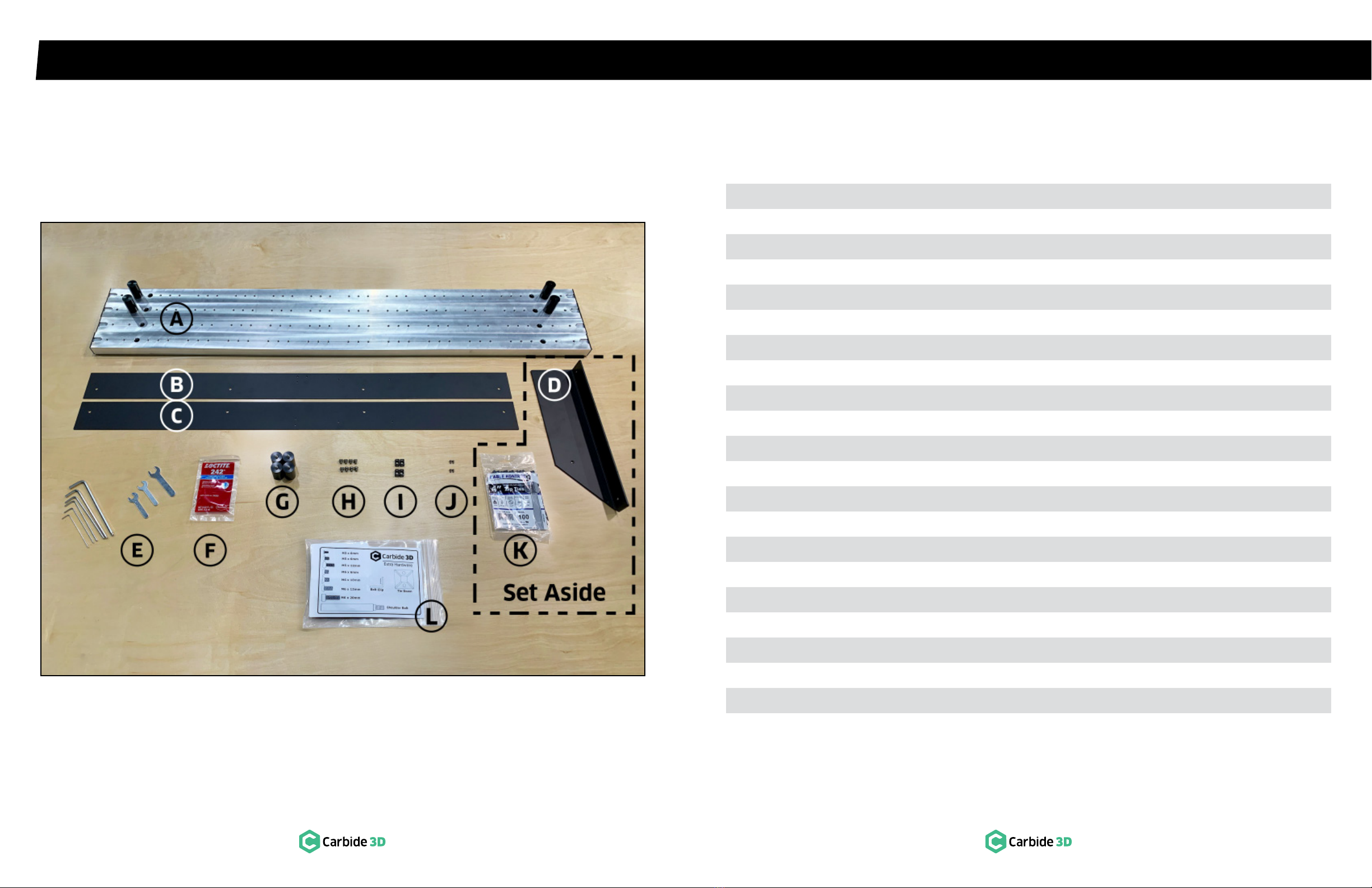
1.1 Review Box 1 Components ...................................5
1.2 Position Crossmembers and Drag Chain Support Panels.........6
1.3 Assemble Baseframe .......................................7
1.4 Install Cable Tie Mounts .....................................7
STEP 2 – Y‑RAILS ........................................8
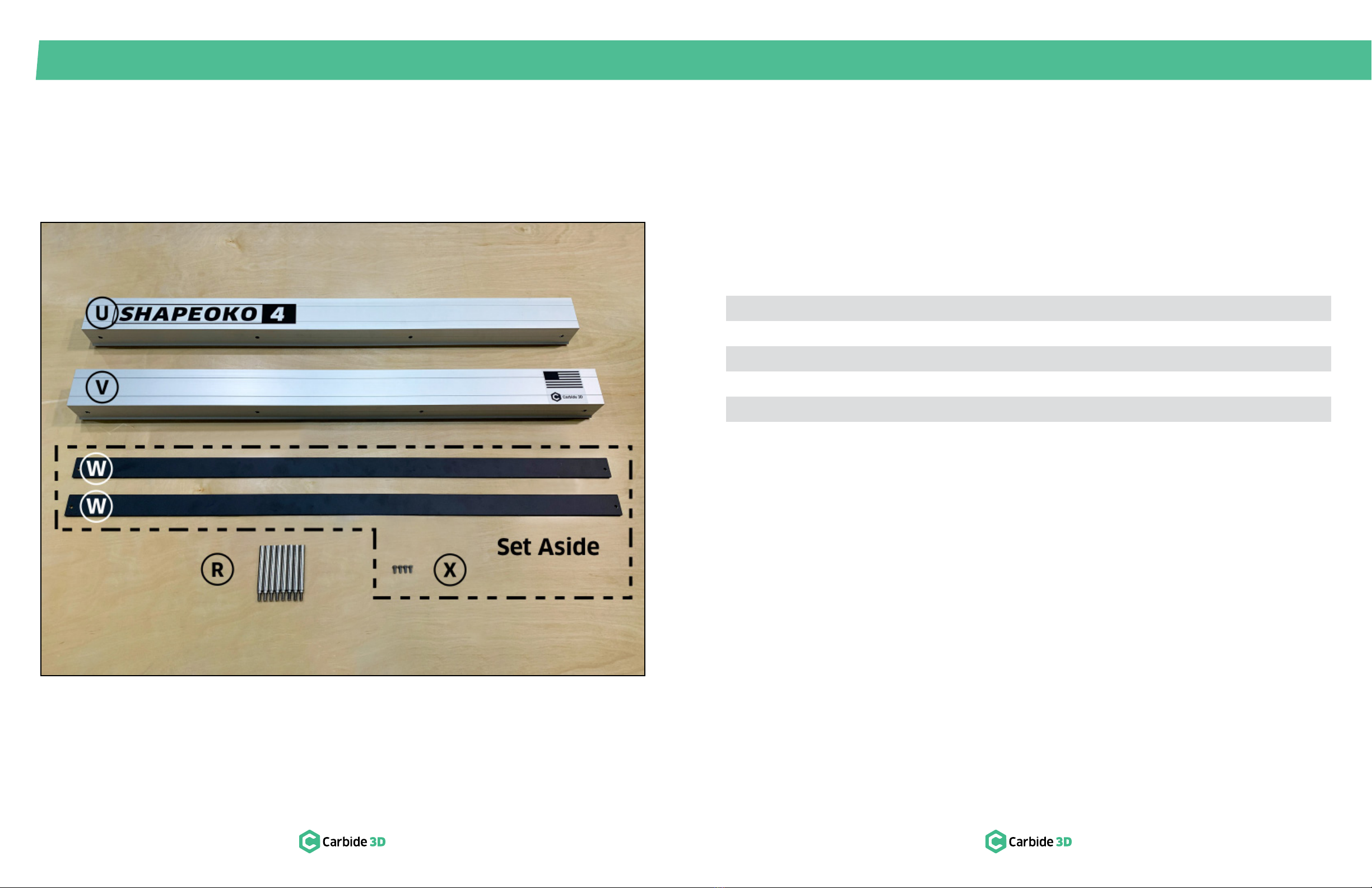
2.1 Review Box 2 Components ..................................9
2.2 Install Y-Left Rail ..........................................10
2.3 Install Y-Right Rail ......................................... 11
STEP 3 – GANTRY ......................................12
3.1 Review Box 3 Components .................................13
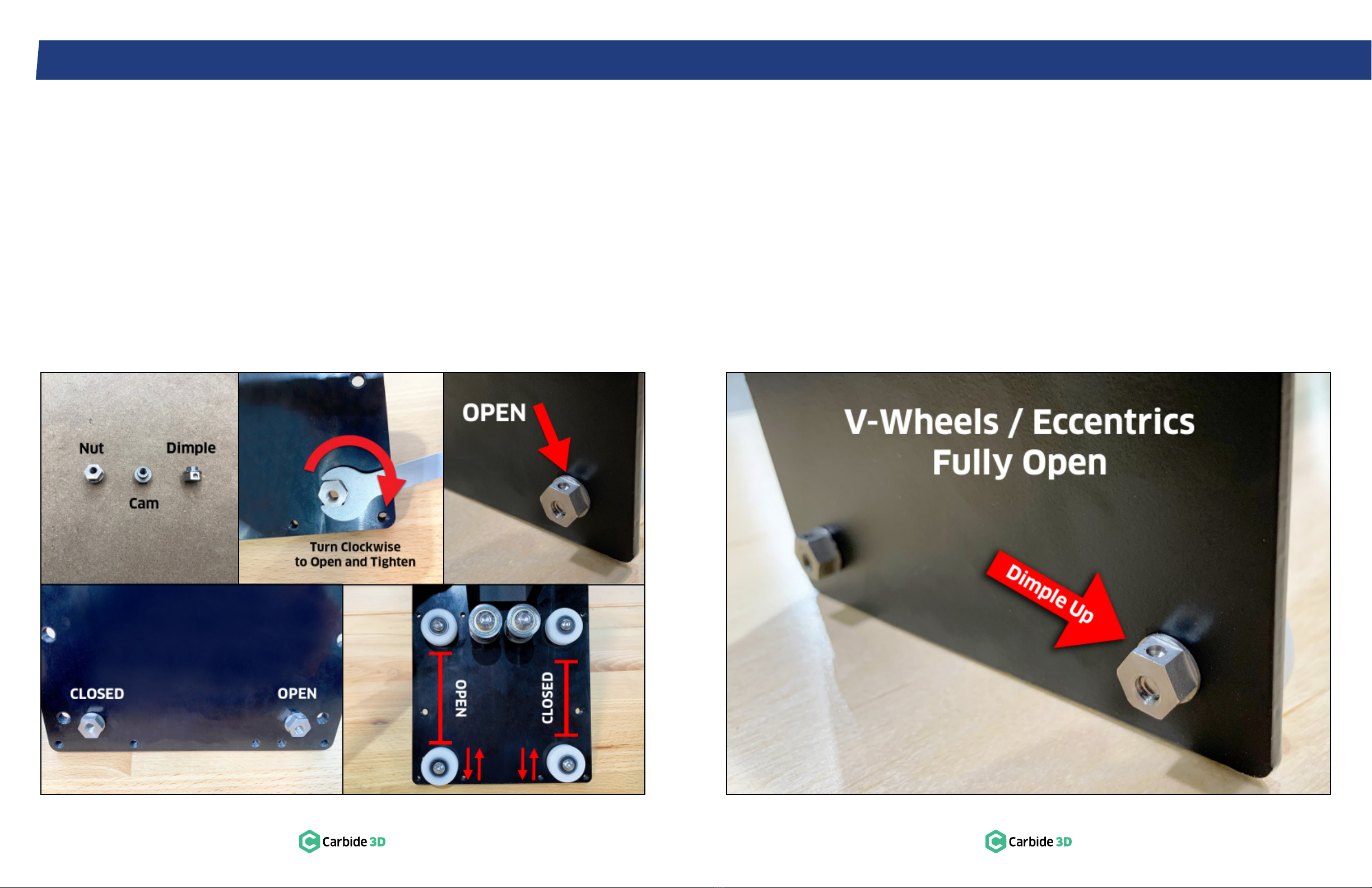
3.2 Eccentric Nuts And V-wheels Explained......................14
3.3 Open V-wheels ...........................................15
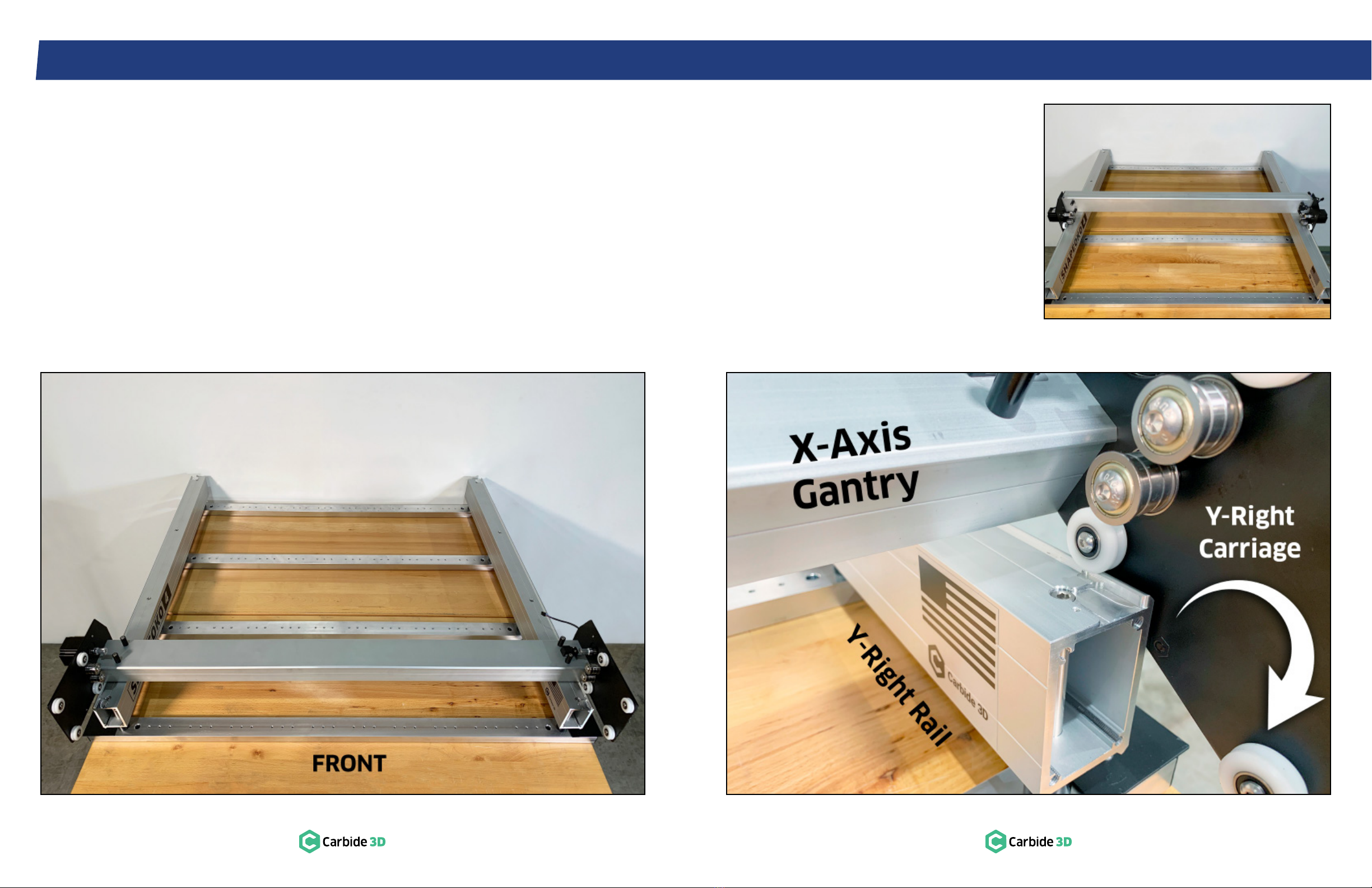
3.4 Install X-Axis Gantry .......................................16
STEP 4 – ENDPLATES ...................................18
4.1 Review Box 4 Components .................................19
4.2 Install Front-Right Endplate................................20
4.3 Install Back-Right Endplate ..................................22
4.4 Install Y-Left Endplates.................................... 23
4.5 Square Machine ......................................... 24
4.6 Install Side Skirts.........................................25
STEP 5 – X/ZASSEMBLY ............................... 26
5.1 Review Box 5 Components ................................ 27
5.2 Open Eccentric Nuts ..................................... 28
5.3 Pre-Assemble V-wheels................................... 28
5.4 Install X/ZCarrier Plate ................................... 29
5.5 Attach Belt Clip to Belt.................................... 30
5.6 Install X-Motor and Belt ....................................31
5.7 Install Data Drag Chain Head Bracket ...........................34
5.8 Install Router Drag Chain Head Bracket .........................35
5.9 Install X/ZAssembly...................................... 36
5.10 Install X-Axis Drag Chain Support Panel .................... 36
5.11 Install Y-Axis Belts........................................ 38
5.12 Install Y-Left Belt ........................................ 38
5.13 Install Y-Right Belt ........................................41
STEP 6 – DRAG CHAIN ................................. 42
6.1 Review Box 6 Components ................................ 43
6.2 Install X-Axis Drag Chain .................................. 44
6.3 Secure X-Axis Drag Chain Head and Tail .................... 45
6.4 Attach Transition Bracket to Y-Axis Drag Chain Head ......... 46
6.5 Install X/Y Transition Bracket and Y-Axis Drag Chain .......... 46
6.6 Secure Y-Axis Drag Chain Tail ..............................47
6.7 Attach Cable Tie Down ....................................47
STEP 7 – ROUTER ..................................... 48
7.1 Review Box 7 Components................................. 49
7.2 Install Router Mount ......................................50
7.3 Install Router.............................................50
7.4 Prepare Drag Chains .....................................52
7.5 Insert Power Cable ....................................... 53
7.6 Attach Transition Bracket to Y-Axis Drag Chain Head..........54
7.7 Install X-Axis Drag Chain ..................................55
7.8 Secure X-Axis Drag Chain Head and Tail ....................55
7.9 Install X/Y Transition Bracket and Y-Axis Drag Chain .......... 56
7.10 Secure Y-Axis Drag Chain Tail ............................. 57
7.11 Attach Cable Tie Down to Drag Chain Support Panel ......... 57
STEP 8 – HYBRID TABLE ............................... 58
8.1 Review Box 8 Components ................................ 59
8.2 Install Hybrid Extrusions ..................................60
8.3 Install MDF Strips .........................................61
STEP 9 – CONTROLLER ................................ 62
9.1 Review Box 9 Components ................................ 63
9.2 Install Controller Mount ................................... 64
9.3 Install Controller ......................................... 65
9.4 Attach Grounding Wire ...................................65
9.5 Connect Controller Cables ................................66
9.6 Connect Cables ......................................... 68
9.7 Tidy Cables.............................................. 69
9.8 Connect Power and USB.................................. 70
9.9 Install an End Mill ........................................ 70
STEP 10 – SET UP MACHINE‑CONTROL SOFTWARE ........72
10.1 Download CAD/CAM and Machine-Control Software ......... 72
10.2 Connect to Machine .................................... 72
10.3 Update Machine Settings .................................72
10.4 Check Proximity Switches .................................73
10.5 Home the Machine .......................................73
10.6 Set Up BitSetter Accessory (Optional).......................74
10.7 Set Post Processor in Carbide Create (Optional) ..............74
EXTRAS ...............................................76
Beginner Tutorials ............................................ 76
Projects and Inspiration on YouTube and CutRocket............... 76
Join Our Community .......................................... 76
Software User Guides and Tutorials..............................77
Machining Guides .............................................77
Material Guide Videos .........................................77
Workholding and Dust Collection Videos .........................77
Glossary of Terms ............................................ 78
Machine-Use Log............................................. 79
Table of Contents

2docs.carbide3d.com [email protected] 3
Important Safety Instructions
The Shapeoko4 is a machine tool and requires the same caution that should be exercised with any power
tool.
Eye Protection
Always wear safety glasses or goggles which are suitably impact-resistant.
Hearing Protection
Always wear earplugs or ear mus. For long jobs, it may be desirable to wear both. Hearing damage is
cumulative and irreversible, so one should always err on the side of caution.
Respiratory Protection
Always wear a filter or respiratory mask suitable for the type of dust generated by the material being cut. If
necessary, arrange for dust collection and proper ventilation.
Clothing, Hair, and Jewelry
Always ensure that clothing, hair, and jewelry cannot become caught in the machine. Always wear
appropriate clothing; long-sleeved shirts, pants, and suitable footwear are recommended. When metal-
working, gloves and an apron are also recommended.
Machine Safety
Never reach into the machine’s working envelope while it is running. Always shut o and unplug the router
to perform tool changes, adjustments, and maintenance. Never leave the machine running unattended.
Always inform someone before operating the machine and check in with them after successfully
completing work. Never allow children to use the Shapeoko4 unsupervised.
Shut Off Machine When Not In Use
Always make sure to power down the Shapeoko4 when you are finished using it.
Fire Prevention
Consider the possibility of a fire caused by friction from the router and take suitable fire prevention
precautions (e.g. having a fire extinguisher handy and other suitable precautions).
Outlet Requirements
Plug the router into an outlet that has a dedicated on/o switch. Be sure this is accessible while the
machine is running, in case you should need to shut o the Shapeoko4 immediately.
End Mill Safety
Use care when handling end mills—both to avoid being cut and to avoid damaging them. Handling end
mills with suitable gloves, or using a cloth to avoid contaminating them, is recommended. Inspect end mills
carefully before each use, and ensure that they are securely held by the collet.
Debris Disposal
Recycle or safely dispose of milling debris and dust, keeping in mind flammability, (potential) spontaneous
combustion, and chemical considerations. Even natural materials can have disposal implications. For
example, walnut wood dust is allelopathic (it inhibits plant growth), an irritant to the skin and respiratory
tract, and potentially poisonous to some animals. All of these possible disposal implications are in addition
to the spontaneous combustion hazard posed by all types of sawdust.
Shipping Box 2 Contains
Step 5: X/ZAssembly Box
Step 6: Drag Chain Box
Step 7: Router Box
Step 8: Hybrid Table Box2
Step 9: Controller Box
Sweepy 65 V2.0 Box
Shipping Box 1 Contains
Step 1: Baseframe Box
Step 2: Y-Rails Box
Step 3: Gantry Box
Step 4: Endplates Box
Inventory
The packaging for your Shapeoko4XXL was designed to facilitate easy assembly. Your Shapeoko4XXL
arrives in two shipping boxes: box 1 contains components you will need to complete steps 1–4, including
your assembly tool kit1, and box 2 contains components you will need for steps 5–9. The individual boxes
in the shipping packages are self-contained steps, allowing you to focus on one step at a time. Early in the
assembly you will be instructed to set a few components aside for later steps. Don’t worry—each set-aside
component is clearly labeled in the component table and at the point you will need to use it. It’s best to
resist the urge to open all of the boxes at once, unless directed to do so by the Carbide3D support team.
PRO TIP: Your Shapeoko4XXL kit has been carefully packaged by hand. If you find that you’re missing
hardware in any step, check the extra hardware bag included in Box 1. If you don’t find the hardware you
need in the extra hardware bag, or one of your components was damaged in shipping, contact us at
1. A pair of flush-cut pliers or scissors and a tape measure may also be helpful during assembly.
2. The hybrid table box is not included if you selected “No Table” when ordering your Shapeoko4.

STEP 1 – Baseframe STEP 1
4docs.carbide3d.com [email protected] 5
1.1 Review Box 1 Components
Item Description Qty
ACrossmember (2 with Pre-Installed Standos; 2 Without Standos) 4
BY-Axis LEFT Drag Chain Support Panel 1
CY-Axis RIGHT Drag Chain Support Panel 1
DController Mount **SET ASIDE FOR USE IN STEP 9** 1
ETool Kit: 1.5, 2, 2.5, 3, 4, 5mm Ball-Nose Hex Keys; 8, 10, 13mm Wrenches 1
FLoctite 242 Medium-Strength Threadlocker (Non-Permanent)
GStando 4
HM6×6mm Button Head Cap Screw 8
ICable Tie Mount 4
JM3×6mm Button Head Cap Screw
KPack of 100 Cable Ties **SET ASIDE FOR USE IN STEP 9** 1
LExtra Hardware Bag3(Not Individually Pictured) 1
(J) M3×6mm Button Head Cap Screw
(M) M5×6mm Button Head Cap Screw
(N) M5×12mm Socket Head Cap Screw
(H) M6×6mm Button Head Cap Screw
(O) M6×10mm Flat Head Screw
(P) M6×12mm Button Head Cap Screw
(Q) M6×20mm Socket Head Cap Screw
(R) Shoulder Bolt
(S) 15mm Universal Belt Clip
(T) Self-Adhesive Cable Tie Down
3. The extra hardware bag includes a few of each listed item in case you find you are missing anything
during assembly. The bag label shows a 1–1 illustration of each item for easy identification.
Figure 1-1

STEP 1
STEP 1 – Baseframe
6docs.carbide3d.com [email protected] 7
1.2 Position Crossmembers
and Drag Chain Support Panels
1. Place a drop of Loctite on the threads of one
stando.
2. Locate the two threaded holes on each end of
a crossmember without standos.
3. Screw the stando into the inner-most of the
two threaded holes.
4. Repeat steps 1–3 to install the three (3)
remaining standos.
a. Each crossmember will have 2 standos.
b. Standos will all line up.
Figure 1-2
1.3 Assemble Baseframe
1. Use a 4mm hex key and eight (8) M6×6mm
BHCS to loosely attach the support panels to
the crossmembers. See Figs. 1-2 and 1-3.
a. Snug the screws, then back out ¼ turn.
b. Don’t worry about squaring the baseframe
yet.
Figure 1-3
1.4 Install Cable Tie Mounts
1. Use a 2mm hex key and four (4) M3×6mm
BHCS to secure two (2) cable tie mounts to
each support panel. See Fig.1-3.
a. Secure mounts to the wide-set M3
integrated nuts toward the back.
5. Position the four crossmembers horizontally
across your table. See Fig. 1-2.
a. Standos up, about 10 inches apart.
6. Check each stando and make sure each is
finger-tight.
7. Position the two support panels, face up, front
to back, across the outside edges of the four
crossmembers. See Figs. 1-2 and 1-3.
a. Look for outline of nuts to identify back—
they are pressed into back-side of panel.
b. M3 integrated nuts to the outside.
c. Two close-set M3 nuts toward the front.
d. Two wide-set M3 nuts toward the back.

STEP 2
STEP 2 – Y‑Rails
8docs.carbide3d.com [email protected] 9
2.1 Review Box 2 Components
Item Description Qty
UY-Axis LEFT Extrusion Rail with Shapeoko 4 Decal (Y-Left Rail) 1
VY-Axis RIGHT Extrusion Rail with Carbide 3D Decal (Y-Right Rail) 1
WY-Axis Side Skirt **SET ASIDE FOR USE IN STEP 4** 2
RM6×85mm Shoulder Bolt 8
XM5×8mm Button Head Cap Screw **SET ASIDE FOR USE IN STEP 4** 4
Figure 2-1

STEP 2
STEP 2 – Y‑Rails
10 docs.carbide3d.com [email protected] 11
2.2 Install Y‑Left Rail
1. Position the Y-Left extrusion rail on the four
standos on the left side of the baseframe.
See Fig.2-2.
a. Shapeoko4 decal to inside-front.
b. V-rail to outside.
Figure 2-2
2.3 Install Y‑Right Rail
1. Position the Y-Right extrusion rail on the four
standos on the right side of the baseframe.
See Fig.2-2.
a. Carbide 3D/flag decal to inside-front.
b. V-rail to outside.
2. Use a 5mm hex key and four (4) M6×85mm
shoulder bolts to loosely attach the Y-Right rail
to the standos. See Fig.2-2.
Figure 2-3
a. Insert bolts in order: front, back, center.
b. Ensure bolts fit snugly into the lower
through-holes with the shoulder flush
against the rail as shown in Fig.2-3.
c. Snug the bolts, then back out ¼ turn.
2. Use a 5mm hex key and four (4) M6×85mm
shoulder bolts to loosely attach the Y-Left rail
to the standos. See Fig.2-2.
a. Insert bolts in order: front, back, center.
b. Ensure bolts fit snugly into the lower
through-holes with the shoulder flush
against the rail as shown in Fig.2-3.
c. Snug the bolts, then back out ¼ turn.

STEP 3
STEP 3 – Gantry
12 docs.carbide3d.com [email protected] 13
3.1 Review Box 3 Components
NOTE: Inspect the Y-Axis carriage plates at either end of the gantry for shipping damage.
Item Description Qty
YX-Axis Gantry Assembly (with Pre-Installed X-Axis Proximity Switch) 1
ZX-Axis Drag Chain Support Panel **SET ASIDE FOR USE IN STEP 5** 1
AA Carrier Plate Assembly Box **SET ASIDE FOR USE IN STEP 5** 1
Figure 3-1

STEP 3
STEP 3 – Gantry
14 docs.carbide3d.com [email protected] 15
3.2 Eccentric Nuts And
V‑wheels Explained
Eccentric nuts and V-wheels are used to adjust
the gantry at the intersect between the carriage
V-wheels and the V-rails. A loose connection
here is referred to as slop. To eliminate slop, a
very small amount of tension is added between
the V-wheels and V-rail. Too much tension and
the V-wheels will deform, causing bumpy and
constrained motion. Not enough tension, and the
carriage will wobble. When tension is just right,
the carriages glide smoothly along the rails for the
highest-quality cuts.
Figure 3-3
A dimple on one the side of the nut indicates the
furthest point from center of the oset threads.
When the dimple is facing UP, the distance
between the top and bottom V-wheel is at its
greatest and the V-wheels are OPEN. When
the dimple is facing DOWN, they are CLOSED.
Figs.3-2 and 3-3.
When adding tension to a loose V-wheel, turn
the eccentric nut CLOCKWISE. Turning counter-
clockwise will loosen the bolted connection
between nut and V-wheel. If this happens,
re-tighten with a 10mm wrench and a 3mm hex key.
Not much tension is needed for the carriages to be
secure. The V-wheels should only be snug against
the V-rail. Reach under and spin the V-wheel with
your finger. If it rotates freely, turn the eccentric
nut clockwise until you feel some friction against
the rail and the carriage is free from slop. See
Figs.3-2 and 3-3.
3.3 Open V‑wheels
1. Use the 10mm wrench to fully open the X-Axis
gantry’s four (4) eccentric nuts.
a. Turn CLOCKWISE until the dimple is facing
UP. See Figs.3-2 and 3-3.
NOTE: You may need to use a 3mm hex key to
loosen the V-Wheel screws to be able to turn the
eccentric nuts.
NOTE: Feel free to use a 10mm combination
wrench in lieu of the included wrench.
Figure3-2

STEP 3
STEP 3 – Gantry
16 docs.carbide3d.com [email protected] 17
Figure 3-4
3.4 Install X‑Axis Gantry
1. Position the X-Axis gantry in front of the
baseframe.
a. V-rail, Y-Axis proximity switch, and four
standos to the FRONT.
NOTE: You may need to have another person help
you lift and lay the gantry in position.
Figure 3-5
Figure3-6
2. Pick the gantry up and rest the X-rail on its
back across the Y-rails. See Fig.3-4.
a. Top of X-rail pointing to the back of the
machine.
b. Top/back V-wheels resting on the left and
right V-rails.
c. Bottom two V-wheels on each side
overhanging the front of the left and right
rails.
3. Rotate the top of the gantry up and back
toward you 90°, so that the bottom V-wheels
on each side align with the lower V-rails. See
Fig.3-5.
4. Slide the gantry into place on the Y-Left and
Y-Right rails. See Fig.3-6.

STEP 4
STEP 4 – Endplates
18 docs.carbide3d.com [email protected] 19
4.1 Review Box 4 Components
Item Description Qty
BB Back-Left Endplate 1
CC Back-Right Endplate (with Pre-Installed Y-Axis Proximity Switch) 1
DD Front-Left Endplate 1
EE Front-Right Endplate (with Integrated Power Button) 1
FF 4-Pin Male-to-Female Power Extension Cable 1
PM6×12mm Button Head Cap Screw 16
WY-Axis Side Skirt **FROM STEP 2 BOX** 2
XM5×8mm Button Head Cap Screw **FROM STEP 2 BOX** 4
Figure 4-1

STEP 4
STEP 4 – Endplates
20 docs.carbide3d.com [email protected] 21
4.2 Install Front‑Right
Endplate
1. Connect the 4-pin female power extension
cable to 4-pin male connector exiting the
back of the front-right endplate. See Figs. 4-2
and4-3.
NOTE: Connectors are polarized and will only
connect one way. Do not force a connection. See
Fig.4-3.
Figure 4-2 Figure 4-3
2. Align the front-right endplate with the four M6
screw holes in the front end of the Y-Right rail.
a. Power button faces front.
a. Tapered corner to the outside/top.
3. Use a 4mm hex key and four (4) M6×12mm
BHCS to secure the endplate to the rail. Fully
tighten.
NOTE: Be careful not to pinch the power wires
between the endplate and the drag chain support
panel or rail.
NOTE: Be careful not to cross-thread the screws.

STEP 4
STEP 4 – Endplates
22 docs.carbide3d.com [email protected] 23
4.3 Install Back‑Right
Endplate
1. Position the back-right endplate at the back
end of the Y-Right rail. See Fig.4-4.
a. Proximity switch to outside/front.
b. Be careful not to pinch the Y-Axis proximity
cable between the endplate and drag
chain support panel or the end of the rail.
Figure 4-4
4.4 Install Y‑Left Endplates
1. Position the two remaining endplates at either
end of the Y-Left rail. See Fig.4-5.
a. Curved flange on the lower part of the
endplate goes to INSIDE.
b. Tapered corners to the outside/top.
2. Use a 4mm hex key and four (4) M6×12mm
BHCS to secure each endplate to the rail. Fully
tighten.
Figure 4-5
2. Use a 4mm hex key and four (4) M6×12mm
BHCS to secure the endplate to the rail. Fully
tighten.

STEP 4
STEP 4 – Endplates
24 docs.carbide3d.com [email protected] 25
4.6 Install Side Skirts
1. Locate the two identical side skirts and
hardware set aside from the step 2 box.
2. Position one side skirt along the bottom-inside
edge of the Y-Right rail. See Fig.4-7.
a. Through-hole to the bottom.
3. Use a 3mm hex key and two (2) M5×8mm
BHCS to secure the skirt to the flanges of the
front and back endplates below the Y-Right
rail. Fully tighten.
Figure 4-7
4.5 Square Machine
1. Slide the gantry as far forward as it will go.
2. Adjust the squareness of the baseframe until
both ends of the gantry simultaneously touch
the front endplates. See Fig.4-6.
3. Use a 5mm hex key and fully tighten the front-
left and front-right shoulder bolts securing the
Y-rails to the baseframe.
a. Fully tighten the remaining shoulder bolts,
moving front to back, sliding the gantry as
you go, and alternating sides.
Figure 4-6
4. Slide the gantry as far back as it will go. Both
ends of the gantry should simultaneously
touch the rear endplates.
5. Use a 4mm hex key to fully tighten the eight
(8) M6×6mm BHCS securing the left and right
drag chain support panels to the baseframe.
4. Position the second skirt along the bottom-
inside edge of the Y-Left rail.
a. Through-hole to the bottom.
5. Use a 3mm hex key and two (2) M5×8mm
BHCS to secure the skirt to the flanges of the
front and back endplates below the Y-Left rail.
Fully tighten.

STEP 5
STEP 5 – X/ZAssembly
26 docs.carbide3d.com [email protected] 27
5.1 Review Box 5 Components
Item Description Qty
GG X/ZAssembly 1
HH Nema 23 Stepper Motor 1
PM6×12mm Button Head Cap Screw 6
ZX-Axis Drag Chain Support Panel **FROM STEP 3 BOX** 1
AA Carrier Plate Assembly Box **FROM STEP 3 BOX** 1
X-Axis Belt Kit 1
(II) 15mm 2GT 1400mm Belt 1
(S) 15mm Universal Belt Clip 2
(N) M5×12mm Socket Head Cap Screw 2
Y-Axis Belt Kit 2
(II) 15mm 2GT 1400mm Belt 2
(JJ) 15mm Belt Clip Pair (Front and Back) 2
(N) M5×12mm Socket Head Cap Screw 4
(J) M3×6mm Button Head Cap Screw 2
(KK) X/ZCarrier Plate 1
(LL) M5×22mm Button Head Cap Screw 2
(MM) V-wheel 2
(NN) Shim 2
(N) M5×12mm Socket Head Cap Screw 4
(OO) Data Drag Chain Head Bracket 1
(M) M5×6mm Button Head Cap Screw 2
(PP) Router Drag Chain Head Bracket 1
(M) M5×6mm Button Head Cap Screw 2
(J) M3×6mm Button Head Cap Screw (+1 Extra) 3
(I) Cable Tie Mount (+1 Extra) 3
(QQ) M4×6mm Button Head Cap Screw 5
(RR) 4-Pin Male-to-Female Y-LEFT Stepper Motor Extension Cable 1
Figure 5-1

STEP 5
STEP 5 – X/ZAssembly
28 docs.carbide3d.com [email protected] 29
5.2 Open Eccentric Nuts
1. Locate the carrier plate assembly box and
the X-Axis drag chain support panel set aside
from the step 3 box.
2. Lay the X/Zcarrier plate on the work surface
with the eccentrics face up and to the bottom.
3. Use the 10mm wrench to open the eccentrics.
See Fig.5-2.
a. Dimple faces UP.
b. Refer back to 3.2 Eccentric Nuts And
V‑wheels Explained, if necessary.
Figure 5-2 Figure 5-3
5.3 Pre‑Assemble V‑wheels
1. Pre-assemble the bottom two V-wheels for the
X/Zcarrier plate in order (see Fig.5-3):
a. M5×22mm BHCS
b. V-wheel
c. M5 shim (washer)
NOTE: Be sure the shim goes between the
V-wheel and the X/Zcarrier plate.
5.4 Install X/ZCarrier Plate
1. Place the X/Zcarrier plate onto the gantry,
aligning the two pre-installed V-wheels on the
top with the upper V-rail.
2. Use the 3mm hex key to install the bottom two
V-wheels on the back of the carrier plate. See
Fig.5-3.
a. Be sure the V-wheels are properly seated
on the lower V-rail.
b. Use a 10mm wrench to hold eccentric nuts
in the fully open position (dimples up).
c. Use a 3mm hex key to tighten the BHCS to
secure the V-wheels to the eccentric nuts.
3. Check the carrier plate movement by rolling it
back and forth along the X-Axis gantry.
4. Use a 10mm wrench to tension the eccentric
nuts.
a. Rotate the eccentric nuts CLOCKWISE to
tension. Adjust a little at a time. Not much
tension is needed.
b. Reach under and spin the V-wheel with
your finger. If it rotates freely, keep
tightening until you feel some friction
against the rail.

STEP 5
STEP 5 – X/ZAssembly
30 docs.carbide3d.com [email protected] 31
Figure 5-4 Figure 5-5
5.5 Attach Belt Clip to Belt
See Fig.5-4.
1. Thread about 2 inches of belt through the
outer slot of the clip, with teeth facing toward
the integrated nut.
2. Loop the belt down through the inner slot and
pull the belt tight against the clip.
3. Bring the two sections of belt together.
Interlock the teeth and extend the belt away
from the integrated nut.
5.6 Install X‑Motor and Belt
1. Locate the X-Axis belt kit.
a. Contains two identical universal belt clips.
2. Thread one end of the belt through a belt clip.
(Refer back to 5.5 Attach Belt Clip to Belt, if
necessary.)
3. Use a 4mm hex key and one (1) M5×12mm
SHCS to secure the belt clip to the top of the
Y-Left carriage. See Fig.5-5.
a. Slotted end of the clip against the rail.
b. Ensure belt teeth interlock where they
meet at the clip.
c. Ensure teeth face down as the belt
extends along the X-rail.
d. Insert SHCS through the outside of the
carriage plate.
e. Fully tighten.

STEP 5
STEP 5 – X/ZAssembly
32 docs.carbide3d.com [email protected] 33
Figure 5-6 Figure 5-8
4. Thread the belt, teeth down, under the two
idlers on the back of the X/Zcarrier plate.
5. Use a small hex key to pull a large loop of belt
up between the two idlers and into the motor
housing. See Fig.5-6.
6. Position the X-motor over the threaded screw
holes on the motor housing. See Fig.5-7.
a. Motor pulley faces into motor housing and
under the belt loop.
b. Motor lead cables extend up.
7. Use a 4mm hex key and four (4) M5×12mm
SHCS to secure the X-motor to the motor
housing. Fully tighten. See Fig.5-7.
8. Pull the slack out of the belt.
a. Look through the slot in the top of the
X-motor housing to make sure the belt
stays properly on the motor pulley.
9. Thread the second belt clip onto the free end
of the belt. (Refer back to 5.5 Attach Belt Clip
to Belt, if necessary.)
10. Hold the clip flat against the end of the X-rail.
11. Adjust the length of the belt so that there is a
2–3mm gap between the clip and the Y-Right
carriage plate. See Fig.5-8.
12. Use a 4mm hex key and one (1) M5×12mm
SHCS to secure the clip.
a. Maintain downward pressure on the clip.
b. Fully tighten the screw until the belt snaps
back against the rail when gently lifted.
NOTE: Do not overstretch the belt. Stretching
more than 3mm could damage the belt or motors.
Figure5-7

STEP 5
STEP 5 – X/ZAssembly
34 docs.carbide3d.com [email protected] 35
Figure 5-9 Figure 5-10
5.7 Install Data Drag Chain
Head Bracket
1. Position the (shorter) data drag chain head
bracket on the BACK of the X/Zcarrier plate
(see Fig.5-9):
a. Align to the two (2) M5 holes in the upper-
right corner (from the rear).
b. Flange down.
2. Use a 3mm hex key and two (2) M5×6mm
BHCS to secure the bracket to the
X/Zassembly. Fully tighten.
5.8 Install Router Drag Chain
Head Bracket
1. Position the (longer) router drag chain head
bracket on the BACK of the X/Zassembly (see
Fig.5-10):
a. Align to the two (2) M5 holes in the upper-
left corner (from the rear).
b. Flange down.
2. Use a 3mm hex key and two (2) M5×6mm
BHCS to secure the bracket to the
X/Zassembly. Fully tighten.

STEP 5
STEP 5 – X/ZAssembly
36 docs.carbide3d.com [email protected] 37
Figure 5-11 Figure 5-12
5.9 Install X/ZAssembly
1. Slide the Z-Axis plate on the front of the
X/Zassembly until it is centered on the linear
rails and all six M6 holes on the front of the
assembly are accessible. See Fig.5-11.
2. Position the X/Zassembly over the FRONT of
the X/Zcarrier plate. See Fig.5-11.
a. Z-Axis plate facing front.
b. Z-Axis stepper motor on top.
3. Use a 4mm hex key and six (6) M6×12mm
BHCS to secure the X/Zassembly to the M6
holes on the carrier plate. Fully tighten.
5.10 Install X‑Axis Drag
Chain Support Panel
1. Identify the back-side of the X-Axis drag chain
support panel. See Fig.5-13.
a. The set of two M3 integrated nuts, spaced
about 1 apart and located at each end of
the panel, are pressed into the BACK-SIDE
of the panel. Look for the outline of these
four nuts on the back-side.
IMPORTANT: Be sure to correctly identify the
front and back of the support panel. The panel will
only work properly one way.
2. Use a 2mm hex key and three (3) M3×6mm
BHCS to secure three cable tie mounts to
three right-side up nuts on the BACKSIDE of
the support panel.
3. Position the support panel RIGHTSIDE UP
across the top-back of the gantry.
a. Tapered corners to the back.
b. Five M5 holes to the front.
c. Two integrated M3 nuts at each end.
4. Use a 2.5mm hex key and five (5) M4×6mm
BHCS to secure the support panel to the
gantry. See Fig.5-12.Figure5-13
Table of contents
Popular Wood Router manuals by other brands

Bosch
Bosch PR20EVS Operating/safety instructions

Clarke
Clarke CONTRACTOR CR1C Operation & maintenance instructions

Hoffmann
Hoffmann MU3-P Operating and maintenance manual

Stanley
Stanley SRR1200-RU Original instructions

Status
Status RH1800 Original instructions

Hitachi Koki
Hitachi Koki M 12V2 Handling instructions