shiftingunexpectedlywhileinuse,resultingin
propertydamageorseriouspersonalinjury.
Disconnecttherouterfromthepower
supply before installing router into the
table, making adjustments, changing
accessories, removing the router from the
table, performing maintenance, or storing
the tool. Such precautionary safety measures
reduce the risk of unintentional tool operation.
Do not plug router motor power cord into
standard wall outlet. Always plug router
cord into the router table switch box. Power
tool switches and controls need to be within
your reach in emergency situations.
Do not permit fingers to touch terminals on
the plug when inserting or removing plug
from the outlet.
Before connecting router or vacuum to
router table switch box, ensure that the
router or vacuum switch is off and that the
router table switch box is unplugged. Such
precautionary safety measures reduce the risk
of unintentional tool operation.
Before using the router table, verify that
the router is securely clamped in the router
table base. While working, periodically
check the router base fastener clamping
tightness. Vibrations from cutting operations
can cause router motor clamps to loosen and
the router motor may fall from the table.
Before starting to work, ensure that the
power cords from the router accessories,
the switch box, and the extension cord do
not and cannot come in contact with the
router or any moving parts of the router.
Such precautionary safety measures reduce
the risk of injury due to loss of control.
Do not use the router table without the
overhead guard or starter pin guard.
Remove all dust, chips, and any other
foreign particles that can affect its
function. Adjust the guard height so that
it clears the router bit and the workpiece.
The guard will aid in keeping hands from
unintended contact with the rotating bit.
Do not use bits that have a cutting
diameter that exceeds the clearance hole
in the tabletop insert plate or insert rings.
Bit could contact insert plate or insert ring,
throwing fragments.
Never use dull or damaged bits. Damaged
bits can snap during use. Dull bits require
more force to push the workpiece, possibly
causing the bit to break or the material to
kick back.
Handle sharp bits with care. Such precau-
tionary safety measures reduce risk of injury.
Do not alter insert ring or insert plate bit
hole. Match the cutting diameter of the
bit to the inner diameter of the insert ring
or insert plate bit hole such that the
difference is no less than 1/16 in. on a side.
Insert rings are meant to reduce the gap
between the cutting diameter of the bit and the
table so that workpieces maintain full support
of the table while routing.
Install bit in accordance with instructions
in the router manual. Securely clamp the
router bit in the collet chuck before making
any cuts. Securing the bit before cutting
reduces the risk of the bit becoming loose
during operation.
Never place your fingers near a spinning
bit or under the guard when the router is
plugged in. Such precautionary safety
measures reduce the risk of injury.
Never hold the workpiece on the outfeed
side of the bit. Pressing the workpiece
against the outfeed side of the fence may
cause material binding and possible kickback,
pulling your hand into the bit.
Guide the workpiece with the fence to
maintain control of the workpiece. Do not
place the workpiece between router bit
and fence while routing the edge. This
placement will cause the material to become
wedged, making kickback possible.
Only use touters for working with wood,
woodlike products, plastic, or laminates.
Do not use router and router table for
cutting or shaping metals. Be sure
workpiece does not contain nails or other
hard objects. Cutting nails may cause loss
of control of the tool or workpiece.
Never start the tool when the bit is
engaged in the material. The bit-cutting edge
may grab the material, causing loss of control
of the workpiece.
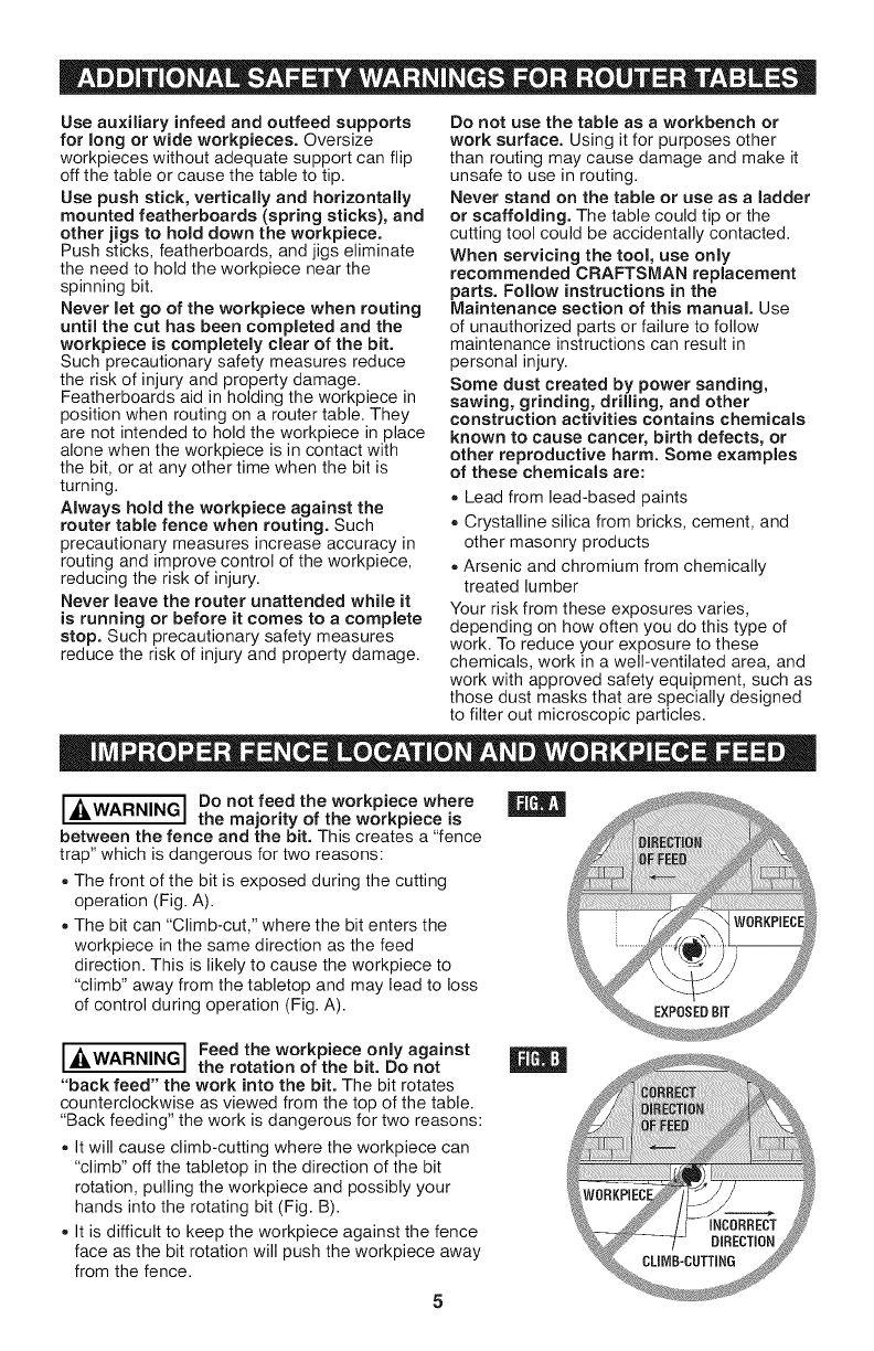
Feed the workpiece only against the
rotation of the bit. Do not "back feed" the
workpiece into the bit. The bit rotates
counterclockwise as viewed from the top of
the table. "Back feeding" will cause the
workpiece to "climb" up on the bit, pulling the
workpiece and possibly your hands into the
rotating bit.
Do not feed the workpiece into the bit
where the majority of the workpiece is
between the fence and the bit. This creates
a "fence trap" which is a hazardous situation
due to the bit being exposed. This will cause
the work to "climb-cut" away from the tabletop
and may lead to loss of control during
operation.
Do not cut material that is warped, wobbly,
or otherwise unstable. The router table is
designed to cut fiat, straight, and squared
materials, if the material is slightly curved
but otherwise stable, cut the material with
the concave side against the table or fence.
Cutting the material with the concave side up
or away from the table may cause the warped
or wobbly material to roll and kick back,
causing the user to lose control.