ENJOY GODFATHER User manual

CREATIVE MULTI CHANNEL AUDIO PROCESSOR
USER GUIDE

The GodFather 3
Important Safety Rules 3
Caution 3
Assistance 3
Warning 4
Positioning 4
Installation 4
Stand Alone 4
Eurorack 4
Patchbay 6
AUDIO INPUT 6
AUDIO OUTPUT 6
CV Input 6
CV OUT 6
GATE INPUT / CLOCK INPUT 6
GATE OUT 7
MIDI IN INPUT 7
MIDI OUT 7
The GodFather Overview 7
Channels section 8
Processing for each channel 9
● Level 9
● EQ Shape 9
● Saturator 9
● Pan 10
● Gain 10
● Delay 11
“TIME” 11
“OFFSET” 11
“FEEDBACK” 12
● DOUBLE PULSE 14
● FDPD 14
● Filter Hi pass / Low pass 15
Menu - Commander Area 15
Global Tempo - Tap Tempo, Midi Clock Cv - Gate 15
Global Tempo Setting 15
Manual: 15
MIDI clocks 16
CV Gate 16
1

Reverb 16
LFO 16
Amount 17
Rate 17
Destination 17
Shape 17
Working Mode 17
Normal 18
Add 18
Change 18
Automation 18
Mute a channel 19
Bypass 19
MIDI 19
In 19
Out 19
MIDI Control Change Table 19
Software update 21
WARRANTY: 22
Legal disclaimer 23
User Manual The GodFather Multichannel Audio Processor RL.0.901A
2

The GodFather
The GodFather is the first creative multichannel audio processor designed to inspire
Its secret is an unique combination of manipulation parameters that will make you
definitively abandon the conventional mixing concepts and immediately improve your
creative skills.
In addition to the complex mixing functions like COMPRESSOR, SIDECHAIN, SHAPE
EQ, PAN, STEREO WIDTH, GAIN STAGING, it provides a killer section of
INDEPENDENT EFFECTS FOR EACH OF THE 4-INPUT CHANNELS
Important Safety Rules
1. Read these instructions.
2. Pay attention to any warnings.
3. Follow all instructions.
4. Do not use the unit near water.
5. Clean only with a dry cloth.
6. Carry out the installation following the instructions provided by the manufacturer.
7. Do not install the unit near heat sources, such as heaters, stoves or other devices
capable of
producing heat (including amplifiers).
8. Disconnect the unit during heavy storms or long periods of non-use.
9. Any repairs must be carried out by qualified technical personnel. Assistance is
required when
the unit is damaged in any way (for example: liquid or objects have fallen into the
unit, the unit
has been exposed to moisture or rain, the unit does not work correctly or has fallen).
10. Neverhitorpressexcessivelyonthedisplay.
11. The contents of the memory can be irreparably lost due to malfunctions, or due to
incorrect use of the
unit. Enjoy Lab assumes no responsibility for the loss of stored content (presets /
settings) which may be lost.
Caution
Any changes and/or modifications not expressly approved in this manual may
void your authority in operating with the equipment.
Assistance
Each technical intervention must be carried out by qualified personnel only.
3

Warning
To reduce the risk of fire or electric shock, do not expose the unit to dripping or
splashing of any kind of liquid and make sure that there are no objects containing
liquids, such as vases or glasses, placed on it.
Do not install in limited spaces.
Positioning
Depending on the material and temperature of the surface you place the unit on,
the rubber feet may discolor or stain the surface.
Installation
Stand Alone
Turn off all peripherals before making any connections.
After making all the connections, be sure to turn on the audio sources plugged in
first, then The GodFather and then all the rest of the equipment (mixers,
amplifiers, speakers).
Failure to observe this order could cause malfunction or failure.
There is no power switch on your The Godfather. Once connected to the power
supply, the unit is On.
Be sure to use only the AC adapter supplied with the unit.
Eurorack
USING The GodFather AS A EURORACK MODULE
The GodFather can be removed from its case and installed into a Eurorack
system as a 60HP module.
Before doing this, it is important to note that The GodFather draws a maximum of
900mA from a +12V rail due to the many LEDs available on the panel. It does not
use the -12V rail at all. Make sure there is enough headroom on the +12V rail in
your system to power the Godfather.
It is possible to exclude the LED section to absorb less current by following the
instructions below.
NOTE: You will need to know the current rating of the system's +12VDC rail and
the current draw of the +12VDC rail from all modules in the combined system.
4

The sum of all current draw at +12VDC should never exceed the power supply
rating.
Note that it is good practice to leave some headroom to reduce stress on the
power supply.
Enjoy Lab accepts NO responsibility or liability for improperly installed modules.
TO INSTALL The GodFather IN A EURORACK SYSTEM
1.Disconnect external power from the unit.
2. Remove the eight black M3 screws on the front panel and keep them
somewhere safe. You will need them again.
3. Slowly lift the panel from the case, so that you can see the two cables going to
the front panel module.
4. Disconnect the power cable from the front panel and the USB cable from the
power board. The module is now free from its enclosure.
5. Look at the back of your The GodFather module. There is a 16-pin power
header on the back of the PCB that accepts a 16-pin Eurorack power ribbon
cable (not included).
6. Connect PIN-1 (-12V) of the power ribbon cable to PIN-1 of the GodFather
Eurorack power header. The darkened wire (typically red) on the ribbon cable
indicates the PIN-1 (-12V) side of the cable.
make sure that the red line on the
cable should be placed matching the
−12V side on your power board:
please double check with your power
board supplier that the marked side is
the −12V.
Enjoy Lab may not be held responsible in any way for probems or damage to persons or property or to the device itself, if the
device is not connected as indicated above.
7. After power is connected, your GodFather may be installed into the rails of the
Eurorack system case with the eight black M3 screws removed in Step 2.
8. Once fully installed, you may power up your Eurorack system.
Patchbay
Thanks to its semi-modular nature, The GodFather is equipped with a patchbay that
allows creative connections to other electronic music modules and Eurorack
synthesizer systems.
The GodFather contains a total of 19 patch points:
5

● 11 are inputs, identified by the
triangular downward arrow
● 8 are outputs, identified by the
triangular upward arrow.
The Patchbay is designed to work with 3.5mm patch cables only.
A set of 4 is included in your box.
NOTE: When patching, it is OK to split an output signal with a “Mult”, a TS to dual TS
“Y” cable, or by using cables with stackable plugs. Connect only one output signal to a
CV input to prevent over-voltages.
AUDIO INPUT
Each channel has a mono audio input which can accept 10V peak to peak
AUDIO OUTPUT
The audio outputs are available via the 4 jacks, with standard programming
channel 1 is Left, 2 and right, while channels 3 and 4 duplicate the signal of
channels 1 and 2 respectively. Level 10 V peak peak
CV Input
CV INPUT: -10V to +10V
CV OUT
The control signal available via this output reflects the value of the LFO
LFO1 on CV1 OUT
LFO2 on CV2 OUT
CV OUTPUT: 0V to + 5V
GATE INPUT / CLOCK INPUT
A clock signal plugged into this Jack can be used as the Global Tempo
GATE / CLOCK INPUT: 0V to + 5V ( +10V Tolerant-)
(Rising edge = Clock Pulse)
GATE OUT
A clock signal based on the Global Tempo tempo of The GodFather is available
here.
Gate Out value 0V to +5V
6

MIDI IN INPUT
MIDI information is received via this jack using the five-pin DIN socket to 3.5mm
MINI jack (MIDI Type A) adapter included with your The GodFather.
The GodFather can receive master clock (TEMPO) information, and various CC
(Control Change) messages via MIDI (see MIDI Control Change table).
The corresponding LED indicates that MIDI data is being received.
MIDI OUT
see MIDI Control Change tabe
The GodFather Overview
The GodFather is divided into 4 main sections
1. Channels section
2. Function keys
3. Global Section
4. Patchbay
Channels section
Each of the 4 channels is equipped with
7

● Trigger key of the working modes
● Channel “REVOLVER” encoder Assignable with
push button
● Saturation adjustment potentiometer
● Delay level potentiometer
● Double Pulse level potentiometer
● Potentiometer Send Reverb
● Hi-Pass / Low Pass Filter Potentiometer
The channel "REVOLVER" encoder adjusts the audio level of the channel by default.
The function keys assign the parameter to be adjusted for each channel to the channel
"REVOLVER" Encoders.
Press the PAN, COMP, DPD, FDPD or GAIN key to set these knobs to the corresponding
parameter
Processing for each channel
● Level
By rotating the “REVOLVER” encoder relative to the desired channel without
pressing any function key, it is possible to adjust the channel output level.
8

● EQ Shape
Allows you to set the frequencies for the Low cut and High cut filters of each
channel.
Simultaneously press the "SHIFT" key and the "GAIN" key to enter the settings
for the "EQ SHAPE".
Rotating the channel encoder it is possible to select the cut-off frequency of the
“LOW CUT” filter (it cuts the frequencies lower than the specified frequency);
By holding down and rotating the channel encoder it is possible to select the
cutoff frequency of the “HIGH CUT” filter (cuts frequencies higher than the
specified frequency).
● Saturator
Saturator is a wave shaping effect that adds that "dirty, punch, and warmth to the
sound."
The received signals are saturated at the dB level set via the "SATURATOR"
potentiometer on each channel, the sound obtained can become wild and
uncontrollable.
It's a very fun effect to try and tame!
●Compressor
A compressor reduces the gain of signals that exceed a user-definable threshold.
Compression reduces peak levels, increasing headroom (amplitude margin of the
undistorted signal) and allowing the overall level of the signal to be increased.
This gives the signal a higher average level, which results in a louder, more
"punched" sound than an uncompressed signal.
To set the compression values, press the "COMPRESSOR" function key
The screen shows:
Three “Vu-Meters”, respectively “IN”, “GAIN REDUCTION” and “OUT”.
A graph of the “Compressor Transfer Curve.
A column of parameters that can be set.
By rotating the “MENU” encoder it is possible to select the parameter whose
value we want to modify.
The channel "REVOLVER" encoders allow you to adjust the previously selected
parameter for each channel using the "MENU" encoder.
The Threshold slider determines where compression begins. Signals above the
threshold are attenuated according to the value specified by the parameter
“Ratio” (compression ratio) which adjusts the ratio between the input signal and
the output signal.
For example, with a compression ratio of "3", if a signal above the threshold
increases by 3dB, the compressor output will only increase by 1dB. If a signal
above the threshold increases by 6dB, the output will only increase by 2dB. A
"Ratio" of "1" means no compression, regardless of the threshold.
9

The “Gain Reduction” meter shows the amount of gain reduction at any given
moment: the greater the reduction, the more audible the effect.
Since compression reduces the volume of loud signals and increases headroom,
you can use the “MKP” (Make up) control so that peaks reach the maximum
available headroom.
The “Output” meter shows the level of the output signal. Setting “MKP” to the
“AUTO” position will automatically compensate the output level if the “Threshold”
and “Ratio” settings change.
● Pan
The “PAN” (Balance) control positions the signal anywhere in the stereo field.
Adjusts the stereo positioning of each channel. Range: L50–C0 (center) –R50.
Press and hold the "PAN" function key
Rotate the encoder relating to each channel whose position we want to adjust in
the stereo panorama.
Release the PAN function button.
● Gain
Press and hold the "GAIN" function key.
The display will show the “GAIN” screen with the value of the current gain setting.
The "LED PANEL INTERFACE" corresponding to each channel allows you to
have a clear indication of the presence and level of the input signal. An optimal
value of the input signal allows to maximize the signal-to-noise ratio, so that the
noise is minimal.
It can be considered an optimal value when the GREEN LED or YELLOW LED is
reached in the presence of an audio signal with very short flashes of the RED
LED on the peaks (for example on the kick drum peak).
If the input signal is too high (RED LED almost always or always on) or too low
(YELLOW LED rarely on or always off in the presence of the input signal) we
recommend adjusting the output level of the relative sound source connected to
The GodFather, or alternatively adjust the "GAIN" of the GodFather, bringing the
peak level to touch the clip (RED LED).
Rotate the "REVOLVER" encoder relative to each channel whose "GAIN" value
we want to adjust.
Release the “GAIN” function button.
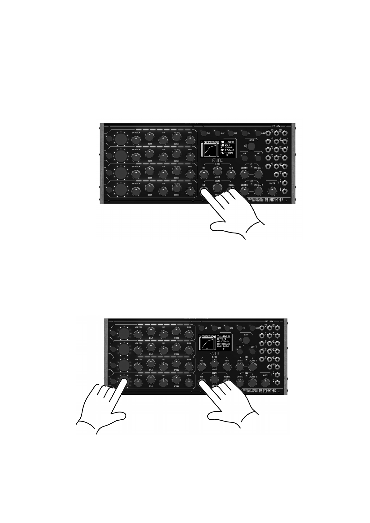
● Delay
The GodFather has independent Delays for each channel, this means that for
each channel it is possible to independently set the "DELAY" level, the "TIME",
the "OFFSET" between left and right and the "FEEDBACK".
10

“TIME” delays are synchronized to “GLOBAL TEMPO”
The delay section consists of 3 encoders:
“TIME”
the tempo adjustment takes place in Divisions of Beats with respect to the
GLOBAL TEMPO
Turning the TIME encoder changes the delay time of all channels simultaneously.
It is possible to adjust the time setting of one or more channels at a time, by
pressing and holding down the revolver encoder of the channel or channels
whose time you want to adjust and adjust it using the TIME encoder.
For example, if we want to modify the delay time of channels 1 and 3, simply
press and hold down the encoders relating to channels 1 and 3 and
simultaneously rotate the delay time encoder.
The LED bar will show the time value set for each channel, while the display
shows all the delay settings for all channels.
“OFFSET”
The "OFFSET" knob allows you to set a delay time between the right and left
audio channels, thus creating a rich and intricate stereophonic panorama.
In position 0 no phase shift is applied between the left and right channels. In
position 4/8 a phase shift equal to 50% is applied with respect to the delay time
of the left channel. (effect commonly called PING PONG)
Rotating the “OFFSET” encoder modifies the delay time of all channels
simultaneously.
To adjust the “OFFSET” setting of just one channel:
press and hold down the encoder of the channel whose time you want to adjust
and adjust the time using the “OFFSET” encoder rotate the “OFFSET” encoder to
set the value.
To adjust the "OFFSET" setting of several channels at the same time (Ex. 1&3) it
is sufficient: keeping the revolver encoders 1 and 3 pressed simultaneously,
11

rotate the “OFFSET” encoder.
The “LED PANEL INTERFACE” will show the set “OFFSET” value for each
channel, while the display shows all the “DELAY” settings of all channels.
“FEEDBACK”
The “FEEDBACK” encoder adjusts how much output signal from each channel is
sent back to the inputs of the delay lines.
By turning the "FEEDBACK" encoder clockwise, you get a greater number of
repetitions.
Setting the "FEEDBACK" parameter to 100% the value of “FEEDBACK” will be
an infinite “∞”, therefore the sound can theoretically be repeated indefinitely like a
loop.
To adjust the Feedback setting of a single channel:
press and hold down the “REVOLVER” encoder of the channel whose Feedback
you want to adjust the value using the “FEEDBACK” encoder.
To adjust the “FEEDBACK” of several channels simultaneously (Ex. 2&4):
keep the “REVOLVER” encoders 2 and 4 pressed simultaneously, rotate the
“FEEDBACK” encoder.
The LED bar will show the set "FEEDBACK" value for each channel.
12
All channel or multi-channel LEDs will be “RED” when the value is 100%
indicating infinite delay mode, while the display shows all delay settings for all
channels.
To temporarily restore the "FEEDBACK" value from any value to a value of "0" for
all channels simultaneously (e.g. to quickly empty the content of the loop
generated in FEEDBACK 100% mode) it is sufficient:
Press the “TIME” encoder in the Delay section
To quickly restore the “FEEDBACK” value from any value to a value of “0” for just
one channel at a time or multiple channels at the same time (ES 2,3,&4):
Press and hold down the “REVOLVER” encoder relative to the single channel or
channels (Ex. 2,3&4) simultaneously
Press the "TIME" encoder in the Delay section to quickly bring the "FEEDBACK"
value back to "0"
when the pressure on the "TIME" encoder is released, the FEEDBACK value will
automatically return from "0" to the pre-set value.
13

● DOUBLE PULSE
The DOUBLE PULSE DELAY that we will also call DPD allows you to add, for
each channel, another two repeat lines within the main delay repeats.
By keeping the DPD function key pressed, the led bars will show the position of
the repetitions of each channel, the yellow led indicates the position of the first
repetition, while the red led indicates the position of the second repetition.
With the "DPD" function key pressed, the first additional delay line of the
DOUBLE PULSE DELAY can be moved by turning the encoder relating to the
channel whose repetition position is to be modified.
By holding down and turning the encoder, however, it is possible to move the
second additional delay line of the DOUBLE PULSE DELAY.
When the second additional delay line is placed in the same position as the first
line, the second delay line is muted.
When the first and second delay lines of the same channel are placed in the
same position, the led turns amber and one of the two repeats is deactivated.
When one or both delay lines of the same channel are moved to position 0, they
are deactivated.
● FDPD
In addition to the position of the two additional lines, the DOUBLE PULSE
DELAY has a dedicated volume control and a dedicated Hi Pass - Low Pass
filter, which allows you to filter only the repetitions of the DOUBLE PULSE
DELAY, leaving the repetitions of the main delay and the DRY signal intact.
To activate and set the filter dedicated to the DOUBLE PULSE, hold down the
function key "FDPD"
The display will graphically show the filtering applied to the repetitions.
By rotating the "REVOLVER" encoder relating to the channel for which we want
to set the double Pulse filter, it is possible to activate and select the cutoff
frequency of the filter.
In HI PASS by turning the "REVOLVER" encoder clockwise
in LOW PASS by turning the "REVOLVER" encoder counterclockwise.
The level of the DOUBLE PULSE DELAY can be adjusted using the dedicated
potentiometer available on the channel lines.
● Filter Hi pass / Low pass
Each channel features a main filter, designed to cut low or high frequencies,
depending on whether the knob is turned clockwise or counterclockwise.
In the central position, (potentiometer has a central detent 0) the filter is disabled
14

Menu - Commander Area
Press the "MENU" knob to access the MENU Commander and navigate through the
available options It is possible to go back in the menu by pressing the OFF key.
Global Tempo - Tap Tempo, Midi Clock Cv - Gate
The GLOBAL TEMPO is the tempo in BPM to which all other active parameters refer
Through the menu it is possible to set the different modes:
- MANUAL
- TAP TEMPO
-MIDI CLOCKS
- CLOCK Gate in input jack
Global Tempo Setting
Manual:
From the main display screen (HOME), rotate the “MENU” knob to choose the
new desired time value. The value appears on the display in BPM.
By holding down the “SHIFT” key and turning the “MENU” knob you can adjust
the setting in 0.1 unit steps.
TAP TIME
To set the “GLOBAL TEMPO” it is possible to beat rhythmically on the “OFF”
button, pacing the desired tempo.
Just tap the "OFF" button a few times following the tempo of the piece of music.
The time will be applied to all DELAY, OFFSET, DOUBLE PULSE.
Note that the tempo is defined and indicated based on the selected division
values.
MIDI clocks
The GodFather will calculate the tempo from the midi messages by averaging the
values received in a few seconds.
CV Gate
The GodFather will calculate the tempo from Clocks received via the GATE1 or
GATE2 Jack depending on the setting, averaging the received values over a few
seconds.
The tempo in BPM set manually or via TAP, Midi or CV controls the same parameter:
the GLOBAL TEMPO of “The GodFather”. Adjustment of one of these controls will
override the adjustment of the other.
15

Reverb
The GodFather features a reverb capable of creating a spacious and warm sound. The
sound of each channel can be sent to the Reverb via the send pot that each channel
has.
The AMOUNT control adjusts the output level of the reverberated signal.
The SIZE control determines how long it takes for the reverberated signal to fade out.
In natural spaces the length is directly related to the size of the simulated space, i.e.
large room - long reverb, small room - short reverb.
The reverb section is also equipped with a dedicated HI PASS FILTER, with a very
high and automatically adjusted resonance curve - its sonic characteristic allows to
emphasize the pre drop phase.
LFO
The GodFather features 2 multi-assignable LFO generators that can be used as a
source for effects, filter and amp modulation.
Each LFO has independent parameters and an LED whose brightness is proportional
to the LFO signal, and indicates the speed and intensity of the modulating signal.
Amount
The LFO AMT (LFO Amount) control adjusts the overall intensity of each LFO
Rate
The RATE (or LFO Frequency) control sets the rate, the LFO oscillators, the rate
is set in Hertz.
Destination
Each LFO generator can be assigned to one global parameter and one
parameter of each channel.
By pressing and turning the RATE/DESTINATION knob of each LFO it is possible
to set the global destinations, such as Reverb, Mode, Master Level …etc…
By simultaneously pressing the "REVOLVER" encoder, it is possible to assign the
LFO to the parameters available on the selected channel.
It is also possible to set a positive or negative (inverted) value of the LFO
modulations for each channel, by turning the “REVOLVER” encoder relating to
the channel whose amplitude and modulation polarity is to be varied clockwise or
counterclockwise.
The LED bars of each channel indicate the amplitude, polarity and intensity of the
modulations for the reference channel
In yellow the modulations of LFO1, in red the modulations of LFO 2.
16

To view the amplitudes of the two modulations on the led bars at the same time,
simply press the two Rate/Destination encoders of each LFO.
Shape
The SHAPE (or waveform) control allows you to choose between 4 waveforms.
To change the waveform, press the "SHIFT" key and rotate while holding down
the RATE/DESTINATION encoder of each LFO
Working Mode
The GodFather is equipped with 3“WORKING MODE”, they allow to change the audio
flow within the Delay section, with the addition, replacement and cancellation of the
input sounds, output sound and within the feedback of the Main Delay.
Each channel can work with different working modes.
To set the working mode, press the SHIFT key and the trigger key corresponding to the
channel whose mode you want to set
The display shows the mode selected for each channel, the leds adjacent to the trigger
buttons indicate the mode set by the color of the led
Amber : Normal
Blue : Add
Green : Change.
Red : Indicates that the mode trigger has been fired.
Normal
Like a classic Delay, all the input sounds enter in the delay, comes out delayed
and has a feedback that regulates how much output signal is sent back to input
from each channel.
By pressing the TRIGGER button, the input sound to the delay line becomes
mute for the time the trigger button is pressed
Add
Unlike the NORMAL MODE, in this case the sound does not enter in the section
Power Delay and then in repetitions until the "TRIGGER" button is pressed.
By pressing the TRIGGER button in correspondence with another sound already
within the repetitions, the new sound is added to existing sound within the
repetitions.
Try it using the feedback in the position ∞ and inserting a long input signal (for
example a lead or a bass) and pressing the trigger button in a quick and
rhythmical way for two or three times. You will notice that the created repetitions
follow exactly the rhythmic sequence realized by pressing the trigger button
repeatedly.
17

Change
Like in the MANUAL ADD mode, the sound does not enter in the Power Delay
section and therefore in the repetitions until the "TRIGGER" button is pressed.
By pressing the TRIGGER button, in correspondence with another sound already
existing in the repetitions, the new sound replaces the previous sound just in the
moment when the TRIGGER button is pressed.
It can also be used to empty the sound of the repetitions, simply by pressing the
trigger button in the absence of input sound, in this way the sound inside the
repetitions is replaced by silence intervals.
Automation
Using LFO, triggers can be triggered automatically
Mute a channel
By pressing the OFF key and the channel "REVOLVER" encoder it is possible to
disable the channel corresponding to the channel encoder pressed
Bypass
Press the OFF and SHIFT buttons simultaneously to deactivate all the processing of
The GodFather and send only the dry signal of entrance.
MIDI
In
If you are using a 5-pin MIDI cable for external control or sync, connect the MIDI OUT
of your MIDI controller to the MIDI IN on your The GodFather. By default, the
GodFather is set to receive MIDI data on MIDI Channel 1.(see MIDI Control Change
table).
Out
If you are using a 5-pin MIDI cable TO external control or sync, connect the MIDI IN of
your MIDI controller to the MIDI OUT on your The GodFather. By default, the
GodFather is set to send MIDI data on MIDI Channel 1.(see MIDI Control Change
table).
MIDI Control Change Table
18

Parameter
MIDI CC#
Range
CH1 Saturator
3
0 - 127
CH1 Delay Level
4
0 - 127
CH1 DPD Level
5
0 - 127
CH1 Reverb Send
6
0 - 127
CH1 Filter
7
0-63 Low Pass / 64 NO
FILTER / 65-127 High Pass
CH2 Saturator
8
0 - 127
CH2 Delay Level
9
0 - 127
CH2 DPD Level
10
0 - 127
CH2 Reverb Send
11
0 - 127
CH2 Filter
12
0-63 Low Pass / 64 NO
FILTER / 65-127 High Pass
CH3 Saturator
13
0 - 127
CH3 Delay Level
14
0 - 127
CH3 DPD Level
15
0 - 127
CH3 Reverb Send
16
0 - 127
CH3 Filter
17
0-63 Low Pass / 64 NO
FILTER / 65-127 High Pass
CH4 Saturator
18
0 - 127
CH4 Delay Level
19
0 - 127
CH4 DPD Level
20
0 - 127
CH4 Reverb Send
21
0 - 127
CH4 Filter
22
0-63 Low Pass / 64 NO
FILTER / 65-127 High Pass
Reverb Size
23
0 - 127
Reverb Amount
24
0 - 127
Reverb Filter
25
0 - 127
LFO1 Amount
26
0 - 127
LFO2 Amount
27
0 - 127
Master
28
0 - 127
TRIGGER 1
32
TRIGGER 2
33
TRIGGER 3
34
TRIGGER 4
35
CH1 LEVEL
70
0 - 127
CH2 LEVEL
71
0 - 127
19
Other manuals for GODFATHER
1
Table of contents
Other ENJOY Computer Hardware manuals


