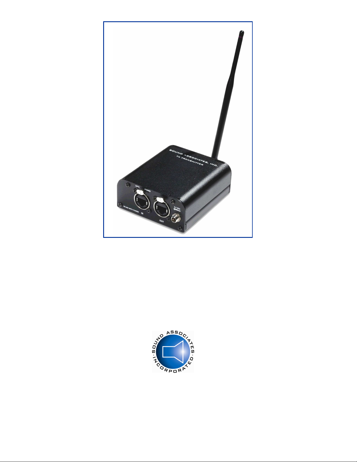
Sound Associates I-CAPTION T4 User manual

OPERATION MANUAL
I-CAPTION® T4 TRANSMITTER/COORDINATOR
I-CAPTION® T4R REPEATER
TRANSMITTER / REPEATER FOR THE AUDIEN® SUITE OF PRODUCTS:
I-CAPTION®, D-SCRIPTIVETM AND AUDIEN® TRANSLATOR
SOUND ASSOCIATES, INC.
424 West 45th Street, New York, NY 10036
Tel (212) 757-5679 Fax (212) 265-1250
Toll free 888-772-7686
Homepage www.soundassociates.com

TABLE OF CONTENTS
IMPORTANT SAFETY INFORMATION ................................................................................................ 1
INTRODUCTION .................................................................................................................................. 2
FEATURES .......................................................................................................................................... 2
UNIT TYPES ........................................................................................................................................ 2
UNPACKING UNIT ............................................................................................................................... 2
MOUNTING .......................................................................................................................................... 3
OTTOM PANEL CONNECTIONS / CONTROLS................................................................................. 3
TOP PANEL CONNECTIONS .............................................................................................................. 4
POWER CONNECTION ....................................................................................................................... 4
INPUT & OUTPUT CONNECTION ....................................................................................................... 4
THEORY OF OPERATION ................................................................................................................... 4
STANDARD DESIGNS AND INSTALLATIONS ..................................................................................... 5
Standard Wireless Repeater Installation … ............................................................................ ……..5
Standard Wired & Wireless Repeater Installation … ................................................................ ……..5
SERVICE OR REPAIRS......................................................................................... ......................... ........6
TECHNICAL SPECIFICATIONS ........................................................................................................... 6
ACCESSORIES ................................................................................................................................... 6
WARRANTY ......................................................................................................................................... 7

- 1 -
Version 1.2 October 2023
IMPORTANT SAFETY INFORMATION
CAUTION: TO REDUCE THE RISK OF ELECTRIC SHOCK,
DO NOT REMOVE COVER (OR BACK).
NO USER-SERVICEABLE PARTS INSIDE.
REFER SERVICING TO QUALIFIED SERVICE PERSONNEL.
DO NOT EXPOSE TO RAIN OR MOISTURE.
The lightning flash with arrowhead symbol within an equilateral triangle is intended to alert the user to the presence of
uninsulated "dangerous voltage" within the product's enclosure. It may be of sufficient magnitude to constitute a risk of
electric shock to persons.
The exclamation point within an equilateral triangle is intended to alert the user to the presence of important operating
and maintenance (servicing) instructions in the literature accompanying the product.
W rnings
Connect this unit’s power supply to an AC outlet of the type stated in this Owner’s Manual or as marked on the
unit. Failure to do so is a fire and electrical shock hazard.
Do not allow water to enter this unit or allow the unit to become wet. Fire or electrical shock may result.
Do not place a container with liquid or small metal objects on top of this unit. Liquid or metal objects inside this
unit are a fire and electrical shock hazard.
Do not remove the unit’s cover. You could receive an electrical shock. If you think internal inspection,
maintenance, or repair is necessary, contact your dealer.
Do not modify the unit. Doing so is a fire and electrical shock hazard.
If the power supply cord is damaged (i.e., cut or a bare wire is exposed), ask your dealer for a replacement.
Using the unit with a damaged power cord is a fire and electrical shock hazard.
If you notice any abnormality, such as smoke, odor, or noise, or if a foreign object or liquid gets inside the unit,
turn it off immediately. Remove the power supply from the AC outlet. Consult your dealer for repair. Using the
unit in this condition is a fire and electrical shock hazard.
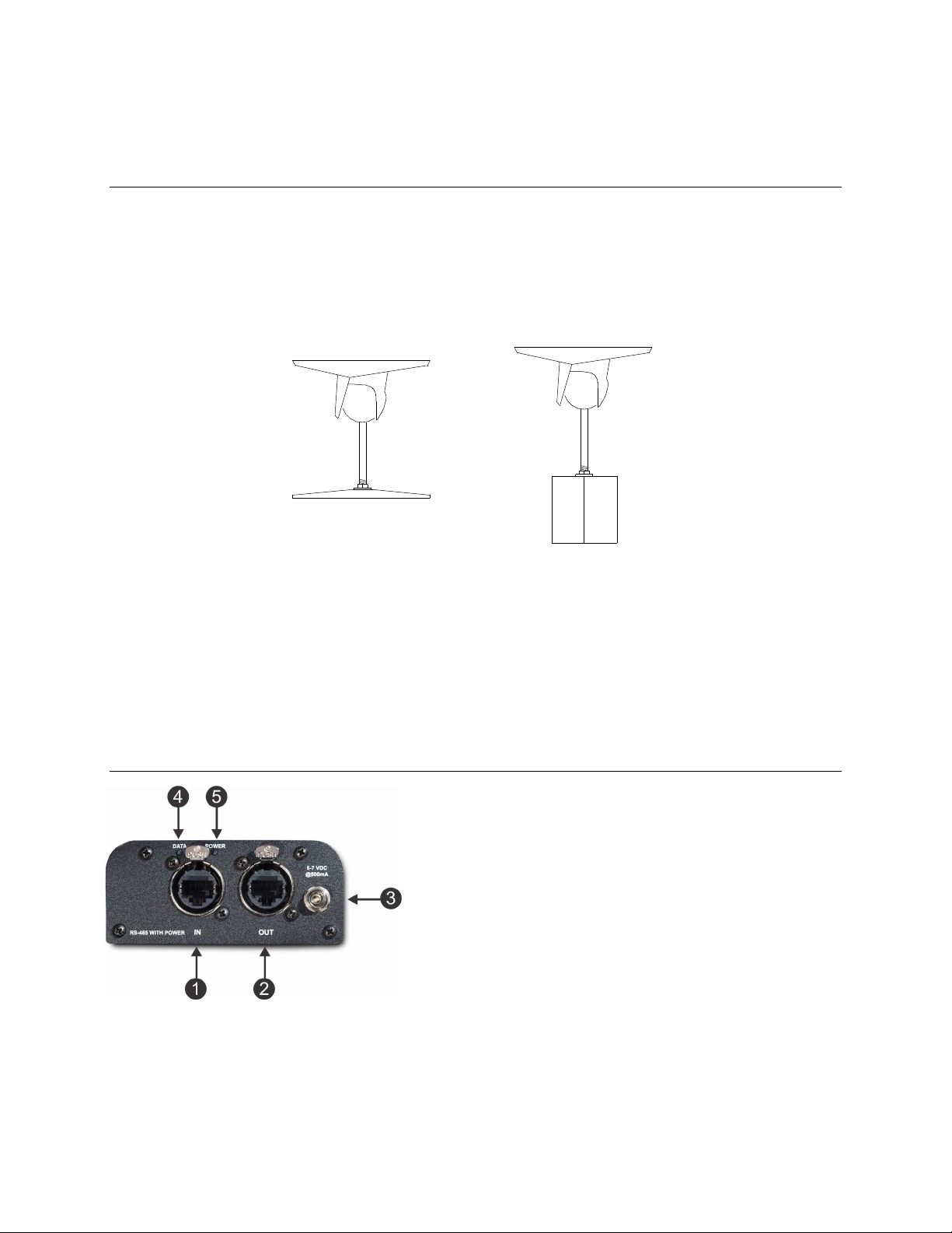
The antennas should be mounted at least 20cm or 8 inches from a nearby person.
C utions
Keep this unit away from the following locations:
o Locations exposed to oil splashes or steam.
o Unstable surfaces, such as a wobbly table or slope.
o Do not install near any heat sources such as radiators, heat registers, stoves, or other apparatus that
produce large quantities of heat.
o Locations subject to excessive humidity or dust accumulation.
o Metal objects that can interfere with its radio transmission.
Do not touch the power plug with wet hands. Doing so is a potential electrical shock hazard.
Certific tions
FCC ID: MCQ-X EEPRO2
The enclosed device complies with Part 15 of the FCC Rules. Operation is subject to the following two conditions: (i.)
this device may not cause harmful interference and (ii.) this device must accept any interference received, including
interference that may cause undesired operation.
If this equipment does cause harmful interference to radio or television reception, which can be determined by turning
the equipment off and on, the user is encouraged to try to correct the interference by one or more of the following
measures: Re-orient or relocate the receiving antenna, Increase the separation between the equipment and
transmitter, or connect equipment and transmitter to outlets on different circuits.

- 2 -
Version 1.2 October 2023
INTRODUCTION
Thank you for choosing a Sound Associates, Inc. manufactured product. All Sound Associates’ products are carefully
designed and engineered for cutting edge performance and world class reliability.
I-Caption® is a state-of-the-art, wireless visual aid that provides verbatim closed captions and subtitling on an
individual hand-held receiver. Originally designed for live theatrical productions, this fully automated system displays
dialogue, lyrics, and sound effects with the efficiency of real-time captioning at a fraction of the cost.
The T4 is designed to serve as both the transmitter and repeaters for the I-Caption®, D-ScriptiveTM and Audien®
Translation systems. It transmits cue information from the control station to R6 audio and video hand-held receivers.
The fully automated system is designed to display captions, audio description or multilingual commentary to wireless
receivers.
The T4 Transmitter when coupled with the R6 Receiver and the CS-6 Control Unit will display I-Caption® slides of
verbatim closed captions or subtitling. The T4 can also trigger playback of prerecorded audio files in mp3 format on
the R6 for audio description for the blind or multi-lingual audio commentary.
FEATURES
Utilizes an innovative 900 MHz (2.4 GHz for international use) mesh network specifically designed to work in
high traffic radio transmission areas.
Wireless repeaters can be added as needed. Covers approximately 300 ft (200 ft at 2.4GHz) radius in ideal
situations.
Strong metal case with EtherCon Connectors makes it extremely durable in harsh environments.
Universal mount allows it to attach to wall, ceiling, or microphone stand.
Hardwired transmit and receive RS-485 data and power down a standard CAT5E / CAT6 cable terminated in
an EtherCon connector.
UNIT TYPES
I-Caption® T4 – The Main Coordinator.
This unit must be hardwired to the Control Station directly. The T4 is the main unit and will communicate
with all additional repeaters.
T4 must be locally powered to ensure proper transmission.
The EtherCon connector is terminated in standard ethernet format.
I-Caption® T4R – Wireless Repeaters.
This unit will repeat the main signal transmitted from the T4 Coordinator. The repeater can be hardwired out
of the T4 Coordinator or repeat wirelessly if within range of the T4 Coordinator or another repeater.
Wired and wireless repeaters must be powered locally with 5-7 VDC.
Note: If hardwired, the repeater should not be in range of the T4 Coordinator or other hardwired T4R
repeaters. Cue fires can be interfered with when two hardwired units on the same network are in range of
each other.
UNPACKING UNIT
As soon as the shipment is received, inspect the unit and all components for damage incurred by
shipping. Also, check to see if all components are enclosed.
Equipment enclosed:
1 T4 / T4R: I-Caption® Transmitter / Repeater
1 6V DC power Supply.
1 ¼ wave antenna 900 MHz (2.4GHz for international units)
1 Instruction manual

- 3 -
Version 1.2 October 2023
If the unit is damaged due to shipping, please keep all packing material and contact the shipping
company as soon as possible. Only the consignee may institute a claim against a carrier if damage has
occurred in shipping; however, Sound Associates will assist in any such event.
MOUNTING
The T4 can mount to a wall or microphone stand with a M 10 mounting bracket.
The T4 utilizes a small speaker mount to secure units to ceiling, walls or microphone stands. Sound Associates
offers the M -10 that includes hardware to attach to a T4 chassis to wood or sheetrock walls and / or microphone
stand. See diagram below.
Each mount attaches to the emitter via two 3/8” 8/32 screws (Note: The mounting screw can not exceed 3/8”
because the screw will damage the PC board).
After deciding on the location of the transmitter / repeater, fix the mounting plate of the M 10 to a secure flat surface
with two screws or bolts with a maximum diameter of 1/4 inch. To allow for proper transmission coverage, the T4
antenna should be mounted 12 inches from all major metal objects. Metal will interfere with wireless transmission.
Use safety wires where necessary when mounting above seated areas.
BOTTOM PANEL CONNECTIONS / CONTROLS
1 – Sign l / Power Input: EtherCon Connector inputs RS-485 signal
from Control Station or Computer. Use a standard Ethernet cable
terminated with an EtherCon or standard Cat 5E connector.
2 – Sign l / Power Output: EtherCon Connector outputs the RS-
485 signal to hardwired remote T4R Repeaters. Use a standard
Ethernet cable terminated with an EtherCon or standard Cat 5E
connector.
3 – Power J ck: 2.5mm power jack connects to outboard 5-7 VDC
power supply.
4 – D t Indic tor: Green LED lights solid when connected to
wired network. LED will flash when data is being Sent.
5 – Power Indic tor: Red LED indicators when unit is powered “on”. Note: T4 Coordinator and T4R Repeaters
must be powered by the external power supply to operate properly.
To T4 Chassis
To Wall/Ceiling
To Mic Stand
To T4 Chassis

- 4 -
Version 1.2 October 2023
TOP PANEL CONNECTIONS
6 – Antenn Connection: Screw ¼ wave swivel antenna to RP-SMA threaded
connector on top of unit. Make sure Antenna does not touch or is blocked by and
metal objects.
POWER CONNECTION
The transmitter is shipped with a 5-7 VDC power supply. The power supply is wired with the inside +DC
and the outer shield as -DC. The DC power supply is equipped with a screw type power plug, make sure
it is fully inserted before tightening the casing screw clamp.
INPUT & OUTPUT CONNECTION
The T4 Coordinator and T4R Repeater have one input and output. It receives power and RS485 data via
a standard CAT 5E cable terminated in standard RJ45 module connector or a rugged lockable Neutrik
EtherCon Connector.
The units use the same wiring configuration as a standard (Straight Thru) CAT 5E cable.
THEORY OF OPERATION
The primary T4 Transmitter / Coordinator is hardwired to the control unit and broadcasts cue information to the
receivers via a wireless mesh network in the 900 MHz or 2.4 GHz range. Additional T4 Repeaters can be added to
the network to increase coverage. Repeaters can be either wireless or hardwired with CAT5E / CAT6 cable
terminated in an EtherCon connector. Voltage is supplied to the T4 via the CAT5E cable for cable runs under 50 ft,
otherwise local 5-7 VDC is required.
The T4 Coordinator and T4R Repeater unit incorporates a sensitive RF transceiver utilizing a peer-to-peer protocol
900 MHz North America and in 2.4 GHz range for operation in global markets. This innovative mesh protocol offers
added network stability through self-healing, self-discovery, and dense network operation.

- 5 -
Version 1.2 October 2023
STANDARD DESIGNS AND INSTALLATIONS
Standard Wireless Repeater Installation:
T4 Coordinator connects directly to the Control Station via CAT5E cable and powered locally with 5-7 VDC
power supply.
T4 Coordinator connects wirelessly to R6 Receivers and T4R Repeaters that are powered locally with 5-7
VDC power supplies.
R6 Receivers and T4R Repeaters receive the data and pass it on to other units as needed.
The power indicator LED on bottom of unit will light red when T4 or T4R are powered on.
The data indicator on bottom of wired T4 Coordinator will light green when connected to the network and will
flash when data is being sent.
Standard Wired & Wireless Repeater Installation (wired T4R in remote location such as outer lobby):
T4 Coordinator connects directly to the Control Station via CAT5E / CAT6 cable and is powered locally with
5-7 VDC power supply.
Hardwired T4R Repeater out of the T4 Coordinator that is out of range of the T4 Coordinator.
Additional T4R Repeaters connect to the hardwired T4R Repeater and are powered locally with 5-7 VDC
power supplies.
R6 Receivers and T4R Repeaters receive the data and pass it on to other units as needed.
The power indicator on the bottom of T4 units will light red when they are powered on.
Data indicator on bottom of the wired T4 & T4R units will light green when connected to the network and will
flash when data is being sent.

- 6 -
Version 1.2 October 2023
SERVICE OR REPAIRS
For technical support or to obtain a Repair Authorization (RA) number, please contact Sound Associates’
Customer Service Department Monday – Friday 10:00 am - 5:30 pm EST at (888) 772-SOUND (7686) or
newyork@soundassociates.com. Please note, equipment cannot be accepted without an RA number.
TECHNICAL SPECIFICATIONS
I/O Connections/Indicators
Input ....................................................................................................... EtherCon connection - RS-485 with power
Output/Link ............................................................................................ EtherCon connection - RS-485 with power
External Power Jack ............................................................................. 2.5 mm DC power jack with locking thread
Antenna Connector ............................................................................... RP-SMA threaded connector
Power Indicator ..................................................................................... Solid red LED
Data Indicator ........................................................................................ Flashing red LED while data is transmitting.
RF Characteristics
Operating Frequency ............................................................................ 900 MHz (ISM 2.4 GHz)
Output Power......................................................................................... 250 mW (24d m) – 900 MHz
50 mW (10d m) – 2.4 GHz
Range .................................................................................................... 300 ft. from receiver to closest T4 or T4R
200 ft. 2.4 GHz
Receiver Sensitivity ............................................................................... -101 d M (1% packet error rate)
RF Data Response ................................................................................ 200 kb/s
Agency Approvals ................................................................................. 900 MHz - U.S. (FCC Part 15, Canada (ISED), Australia (RCM)
2.4 GHz - U.S. (FCC Part 15, Canada (IC), Europe - CE (ETSI,
Japan (Telec), Australia (C-Tick)
Power
Operation ............................................................................................... 5 to 7 VDC
Current Draw ......................................................................................... Nominal 100 mAh
Supply Line ............................................................................................ CAT5E cable terminated in EtherCon connector.
Operation Temperature ......................................................................... 0 to 50 degrees C
Mechanical
Mechanical Dimensions ........................................................................ 4.25” x 3.75” x 1.5”
12” x 3.75” x 1.5” (antenna fully extended straight out)
Weight .................................................................................................... 8 oz.
Finish/Material (Front) ........................................................................... Textured black powder-coat aluminum chassis.
ACCESSORIES
To order accessories or equipment related to the T4 or T4R I-Caption® Transmitter / Repeater, please
contact Sound Associates’ Customer Service Department Monday – Friday 10:00 am - 5:30 pm EST at
(888) 772-SOUND (7686) or newyork@soundassociates.com. For your convenience, we have included
the following part numbers for easy reference:
Accessories:
M 10 – Wall, Ceiling or Microphone Stand Mount
Rel ted Equipment:
I-Caption® R6 Wireless Handheld Receiver.
I-Caption® CS6 – Automation Control Unit
I-Caption® SC10 Charger / carrying case for 10 R6 receivers.

- 7 -
Version 1.2 October 2023
WARRANTY
We, Sound Associates, Inc., warrant to you the original owner or any subsequent owner of each new I-
C ption® T4 / T4R Tr nsmitter / Repe ter that the unit is free of defects in workmanship and materials
for a period of three years from the date of original purchase. (Excluding the extern l power supply
ccessory which c rries 90-d y w rr nty.) If the product fails due to defects in craftsmanship or
materials or does not meet specifications enclosed with the product, Sound Associates will repair or
replace the unit, whichever Sound Associates chooses, free of charge. All repairs will be conducted by
trained personnel at Sound Associates’ facility in a reasonable time. All expenses on remedying the
defect, including return shipping will be borne by Sound Associates. All shipping fees, taxes, duties, and
other customs fees incurred by shipping between foreign countries will be borne by the owner.
Sound Associates is not responsible for the following under this warranty:
malfunctions due to misuse, accident, or neglect.
damage to other products resulting from product failure.
defects or damage caused by unauthorized modifications or service.
Sound Associates, Inc. reserves the right to change the design of any product without notice and with no
obligation to make corresponding changes in products previously manufactured.
This manual suits for next models
1
Table of contents
Other Sound Associates Transmitter manuals
Popular Transmitter manuals by other brands

Emerson
Emerson Micro Motion 5700 installation manual

Hubbell
Hubbell Full-Size Transmitter 31.310 Spec sheet

SeeEyes
SeeEyes SC-IPT1204P user guide

Williams Sound
Williams Sound Transmitter T1-173 Instructions for use and care

Williams Sound
Williams Sound Transmitter T36 Instructions for use and care

Rose electronics
Rose electronics UltraVista VWL-S122DV Installation and operation manual