ENMET EX-5120 User manual

ENMET Corporation
PO Box 979
Ann Arbor, MI 48106-0979
www.enmet.com
Manual Part Number
80003-092
MCN-13-011, 12/20/13
EX-5120
INFRARED 0 – 100% LEL
Sensor/Transmitter
Manual

Table of Contents
1.0 INTRODUCTION .......................................................................................................................................................1
1.1 Unpack...............................................................................................................................................................................1
1.2 Check Order.......................................................................................................................................................................1
1.3 Serial Numbers...................................................................................................................................................................1
2.0 FEATURES OF THE EX-5120 ...................................................................................................................................2
3.0 INSTALLATION OF THE EX-5120..............................................................................................................................3
3.1 Mounting the EX-5120 Enclosure .....................................................................................................................................3
3.2 Wiring the EX-5120 to a Control Unit...............................................................................................................................4
4.0 OPERATION OF THE EX-5120..................................................................................................................................6
4.1 Start up...............................................................................................................................................................................6
4.1.1 Typical Start Up..............................................................................................................................................................................6
4.2 Normal Display Mode........................................................................................................................................................7
4.2.1 Alarm Conditions EX-5120............................................................................................................................................................7
5.0 MAINTENANCE OF THE EX-5120 .............................................................................................................................8
5.1 Maintenance Menu.............................................................................................................................................................8
5.2 Calibration of the EX-5120................................................................................................................................................9
5.2.1 Zero Adjust......................................................................................................................................................................................9
5.2.2 Gas Span.......................................................................................................................................................................................10
5.2.3 Exit Maintenance Menu................................................................................................................................................................10
5.3 Sensor Replacement.........................................................................................................................................................12
6.0 REPLACEMENT PART NUMBERS............................................................................................................................13
7.0 WARRANTY.......................................................................................................................................................14
List of Figures and Tables
Figure 1: EX-5120 Features.......................................................................................................................................2
Figure 2: EX-5120 Mounting Dimensions ..................................................................................................................3
Figure 3: Terminal Positions EX-5120 Sensor/Transmitter .......................................................................................5
Table 1: EX-5120 maintenance Menus Sequence ....................................................................................................8
Figure 4: Calibration Adapter EX-5120 Sensor/Transmitter ......................................................................................9
Figure 5: EX-5120 Maintenance Menu Flow chart...................................................................................................11
Figure 6: Sensor Replacement ................................................................................................................................12
Reference information:
NOTE:[important information about use of instrument – if not followed may have to redo some steps.]
CAUTION:[affects equipment – if not followed may cause damage to instrument, sensor etc…]
W
ARNING
:
[affects personnel safety – if not followed may cause bodily injury or death.]

EX-5120 ENMET Corporation
1
1.0 Introduction
The ENMET EX-5120 infrared sensor/transmitter (S/T) is a 3-wire, 24Vdc, 4-20mA S/T for the detection of combustible gas.
The EX-5120 is meant to be used in conjunction with an appropriate power supply and controller.
The ENMET EX-5120 sensor/transmitter has been designed for use in a Class I, Div. 1, Groups B, C, D, classified areas.
N
OTE
:All specifications stated in this manual may change without notice.
1.1 Unpack
Unpack the EX-5120 and examine it for shipping damage. If such damage is observed, notify both ENMET customer service
personnel and the commercial carrier involved immediately.
Regarding Damaged Shipments
N
OTE
:It is your responsibility to follow these instructions. If they are not followed, the carrier will not honor
any claims for damage.
This shipment was carefully inspected, verified and properly packaged at our company and delivered to the carrier in
good condition.
When it was picked up by the carrier at ENMET, it legally became your company’s property.
If your shipment arrives damaged:
•Keep the items, packing material, and carton “As Is.” Within 5 days of receipt, notify the carrier’s local office and
request immediate inspection of the carton and the contents.
•After the inspection and after you have received written acknowledgment of the damage from the carrier, contact
ENMET Customer Service for return authorization and further instructions. Have your Purchase Order and Sales
Order numbers available.
ENMET either repairs or replaces damaged equipment and invoices the carrier to the extent of the liability coverage,
usually $100.00. Repair or replacement charges above that value are your company’s responsibility.
The shipping company may offer optional insurance coverage. ENMET only insures shipments with the shipping
company when asked to do so in writing by our customer. If you need your shipments insured, please forward a written
request to ENMET Customer Service.
Regarding Shortages
If there are any shortages or questions regarding this shipment, please notify ENMET Customer Service within 5 days of
receipt at the following address:
ENMET Corporation
680 Fairfield Court
Ann Arbor, MI 48108
734-761-1270 734-761-3220 Fax
1.2 Check Order
Check, the contents of the shipment against the purchase order. Verify that the EX-5120 is received as ordered. [Each EX-
5120 is labeled with its target gas.] If there are accessories on the order, ascertain that they are present. Check the contents of
calibration kits. Notify ENMET customer service personnel of any discrepancy immediately.
1.3 Serial Numbers
Each EX-5120 is serialized. These numbers are on tags on the equipment and are on record in an ENMET database.
EX-5120 ENMET Corporation
2
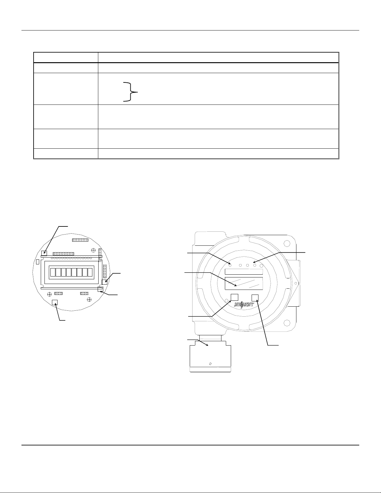
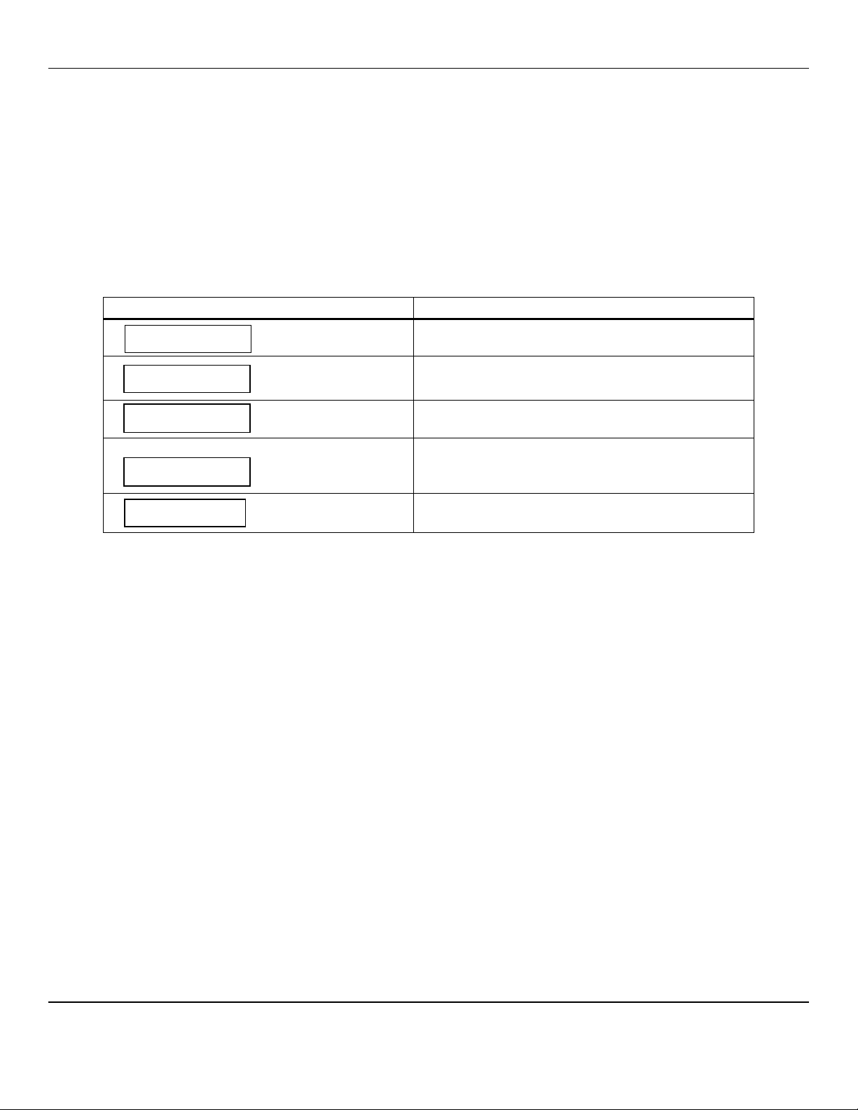
2.0 Features of the EX-5120
See Figure 1 for location of features:
Feature Description
Display LCD: Indicates the level of gas detected by sensor
Gain Potentiometer
(POT)
POT 1: Display contrast adjustment
POT 2:
POT 3: Not Used, Do not adjust
POT 4:
Visual Alarms LED indicators:
Power / Fault Indicator LED, Green / Red
Alarm (3) Indicator Red LED, user adjustable
Magnetic Switches MENU: Advances the instrument display through menus (Zero, Span, Exit)
SELECT: Selects the Zero, Span, Exit menu or sets proper calibration values for Zero or Span
Infrared Sensor For sensing gas at LEL levels, see Section 6.0 for sensor types
Magnetic switches control the instrument maintenance functions. The switch locations are indicated by MENU and SELECT. A
magnetic field pulse is applied by momentarily putting the end of the magnet in proximity to the switch and then removing it.
Referred to as tap. Since the magnetic field penetrates the window, the enclosure cover is not removed in order to perform
calibration.
Three alarm points are preprogrammed into the EX-5120 sensor/transmitters. At each alarm point, an LED on the front panel
is activated. These internal alarm settings are independent of the 4-20mA output alarm values that can be set at a controller.
Figure 1: EX-5120 Features
3 Alarm
Indicators
Power /Fault
Indicator
Display
M
ENU
Magnetic switch
S
ELECT
Magnetic switch
Sensor
External View
Menu Select
POT 3
See Note
POT 4
See Note
POT 2
See Note
POT 1
Display Contrast
Internal PCB View
Note:
POT 2, POT 3and POT 4
are not used, Do Not Adjust
EX-5120 ENMET Corporation
3
3.0 Installation of the EX-5120
CAUTION:
Area must be declassified during installation.
The ENMET EX-5120 gas sensor/transmitter (S/T) is a 3-wire, 24 Vdc, 4-20 mA S/T for the detection of combustible gas.
The S/T is meant to be used in conjunction with an appropriate power supply and controller.
The ENMET EX-5120 sensor/transmitter is in an enclosure rated for use in a Class I, Div. 1, Groups B, C, D, classified area.
Appropriate wiring, conduit and fittings are required for proper installation in a explosion proof rated environment.
CAUTION:Since the sensor/transmitter detects gas only at the sensor location, pay attention to the possible sources of gas, the
density of the gas, locations where the gas may be confined and locations where the gas may damage or injure
property or personnel, when choosing locations of sensor/transmitters.
Also, take into consideration environmental factors when deciding on S/T location. Avoid locations where the S/T
may be damaged by liquid immersion, excessive heat or other known hazards. Also, take precautions to insure
condensation inside of the conduit does not enter the S/T.
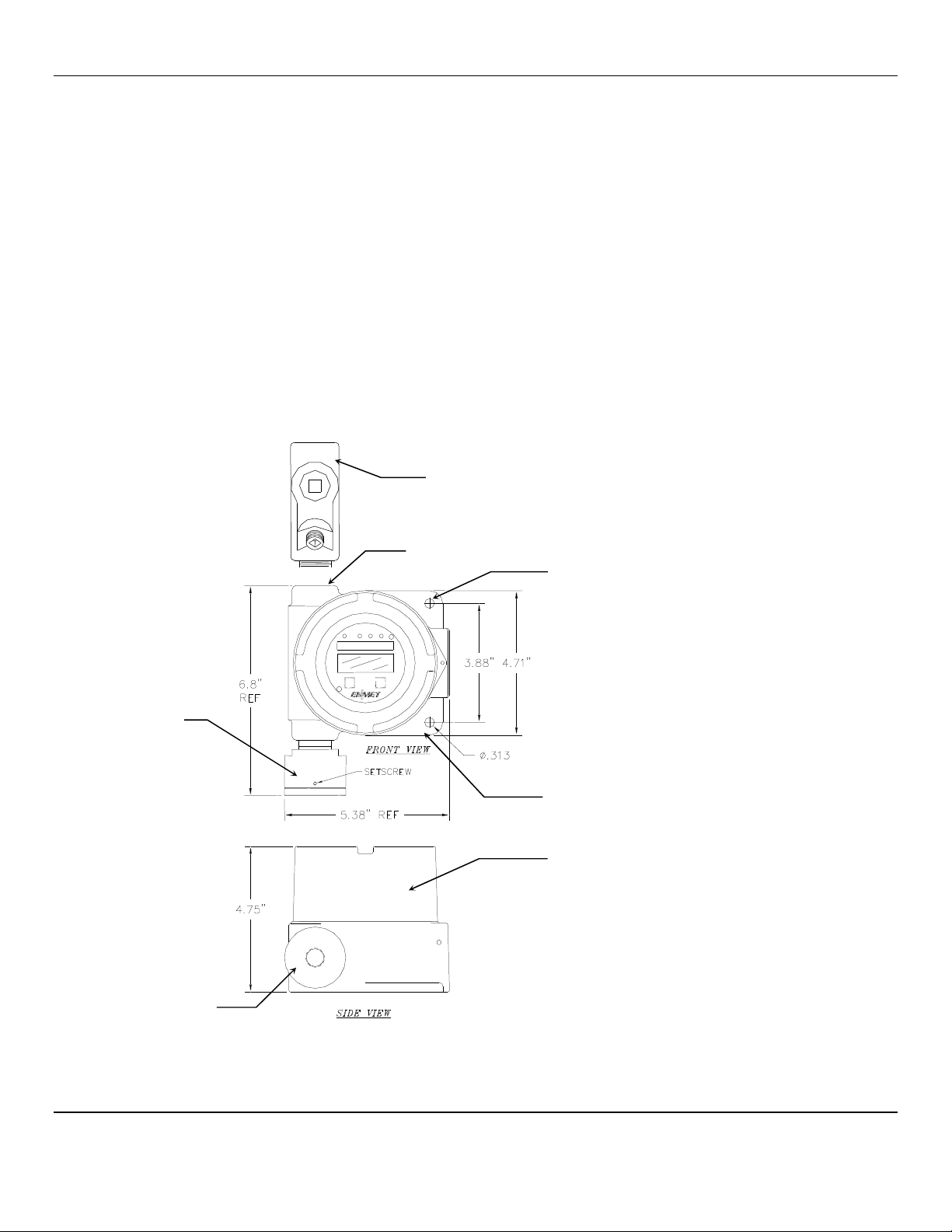
3.1 Mounting the EX-5120 Enclosure
Mount the enclosure, using the two mounting holes provided see Figure 2. Pay particular attention to the source and density of
the gas being detected when choosing the location. Contact ENMET if you have questions regarding your application.
CAUTION:
Before connecting S/T to controller remove the power source to controller. Failure to do so may cause damage to
sensitive components.
Figure 2: EX-5120 Mounting Dimensions
Optional
Conduit fitting
Typically: ½″NPT female
Mounting Holes
2 places, 0.313″
Sensor
Sensor/Transmitter
Enclosure Side View
Sensor
½
″
NPT female
Sensor/Transmitter
Enclosure Top View
Me
nu
Sel
ect
EX-5120 ENMET Corporation
4
3.2 Wiring the EX-5120 to a Control Unit
CAUTION:
Area must be declassified during installation.
Run conduit and 16 AWG (1.5MM
2
)wires to the enclosure from the power supply and controller. If the EX-5120 is installed in
a hazardous location as defined by the National Electrical Code, then ALL wiring must be in accordance with the National code
and any local governing codes.
Open the enclosure, and remove the 2 screws that retain the display overlay to the circuit board.
Use caution when removing the over lay. Do not damage the magnetic switches.
Remove the two overlay standoffs and remove the circuit board, exposing the terminal strips on the bottom of the circuit board.
Do not disconnect the circuit board wiring.
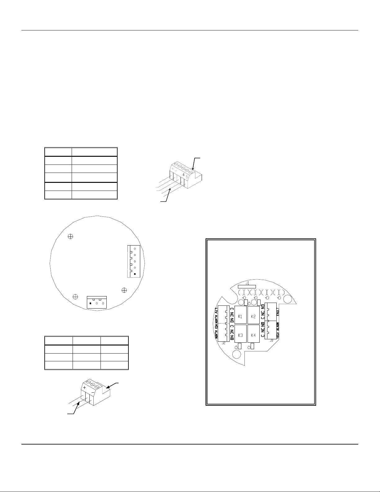
Connect the wires from the controller (power supply) to the supplied J4 plug then attach to J4 terminal.
Connect the wires from the sensor to the supplied J8 plug then attach to the J8 terminal.
See Figure 3 for locations
J4
P
LUG
–
T
ERMINAL TO
C
ONTROLLER
W
IRING
Position
Function
1 +24 V
DC
power
2 –GND
3 s4 - 20 mA out
4* RS-485 D+
5* RS-485 D–
*Contact ENMET for Modbus
Address information
J8
P
LUG
–
T
ERMINAL TO
S
ENSOR
W
IRING
Position Function
Sensor
1 +Power Red
2 sSignal White
3 –GND Black
Circuit Board Bottom View
5
4
3
2
1
J4
J8
1 2 3
Plug J8
To J8
Wires to
Sensor
s
Plug J4
To J4
Wires to
Controller
s
Relay Output Board
Bottom View
Optional Relay Output Board
It is recommended that the auxiliary
alarm be powered separately.
Use 14 – 20
AWG
(2.5
–
0.5
MM
2
) wire.
When on power the relays are energized.
Relays are rated at 0.5 Amp continuous.
N
OTE
: Auxiliary alarms should be powered from an
independent power source separate form the
instrument power to avoid alarm failure due to
controller malfunction.
All wiring must be in accordance with the
National Code and any local governing codes.
EX-5120 ENMET Corporation
5
Figure 3: Terminal Positions EX-5120 Sensor/Transmitter
When wiring is complete, reassemble the
EX-5120
. Use caution when installing the overlay so as not to damage the magnetic
switches. Put the cover back on the S/T
Do Not
apply power to the S/T without the cover in place.
Sensor/Transmitter
Enclosure Cutaway View
Printed Circuit Board
(PCB)
Display Overlay
Display Overlay Screws
(2 places)
Display Overlay Standoffs
(2 places)
Magnetic
Switches
(2 places)
Magnetic Switches
(2 places)
Printed Circuit Board (PCB)
J4 and J8 Terminals are located on the
bottom side of PCB
Display Overlay
Display
Optional
Relay Output Circuit Board
Display Overlay
EX-5120
ENMET Corporation
6
4.0 Operation of the EX-5120
It is best to have the
EX-5120
transmitters powered up, operational and stable for several minutes before applying calibration
or test gas to them.
When the
EX-5120
transmitter is first powered up, it goes through a series of momentary screens, which identify the
instrument model number, serial number and software revision. After all of the momentary screens have been displayed, the
instrument arrives at the Main Gas Display showing the gas concentration and unit of measurement.
Depending on transmitter configuration and calibration condition, the furthest right character in the display may flash a letter
indicating the instrument status.
Consult ENMET Distributor or ENMET Corp
.
4.1 Start up
4.1.1 Typical Start Up
When power is supplied to the
EX-5120,
the S/T will display the following sequence of information:
N
OTE
:
Software revision may cause variations of display output.
Example of Display Function
The instrument: Model
EX
-
5120
The instrument: Serial Number
The instrument: Software Revision
IF
the right most character is a flashing
W
The instrument is in Warm-up mode
This should last about 1 minute
The Signal Output is held at 4mA during warm-up
The instrument: Normal Display Mode
Measurement of target Gas
EX
-
5120
78
-
1256
S/W X.X
0
%
0%W
EX-5120
ENMET Corporation
7
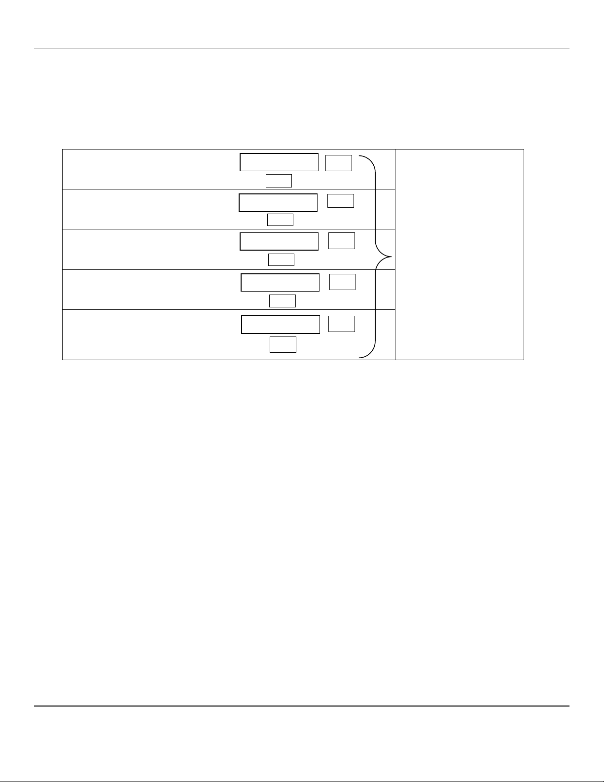
4.2 Normal Display Mode
When the
EX-5120
is installed as described in section 3, and in clean air, the
POWER
green LED is on, the display is lit and
the information on the display is measurement of the target gas detected by the
EX-5120.
The red alarm and fault LEDs are
not lit.
To advance through displays of operational information tap the magnet over the
MENU
button.
N
OTE
:
Software revision may cause variations of display output.
See sequence of operational information below:
Display Measurement of the target gas
Tap the magnet over the M
ENU
button
Display indicates Alarm 1 Set point
Tap the magnet over the M
ENU
button
Display indicates Alarm 2 Set point
Tap the magnet over the M
ENU
button
No Function for the
S
ELECT
button
in this mode
Display indicates Alarm 3 Set point
Tap the magnet over the M
ENU
button
Display indicates mA Span range
(Full Scale)
Tap the magnet over the M
ENU
button
Display returns to gas measurement
Operational Display Flow Chart
4.2.1 Alarm Conditions EX-5120
There are three alarm set points available. These alarm set points can be changed within limits; see the maintenance section of
this manual for the procedure.
If the gas concentration increases above that of the alarm set point, the associated red LED is lit.
0
%
A1:
10
S
ELECT
S
ELECT
MENU
M
ENU
A2:
20
S
ELECT
M
ENU
A3:
50
S
ELECT
M
ENU
mA:
100
S
ELECT
MENU

EX-5120
ENMET Corporation
8
5.0 Maintenance of the EX-5120
CAUTION:
Do not open the
EX-5120
S/T
in a classified area.
CAUTION:
Do Not Attempt A Span Procedure Without Calibration Gas Applied to The Sensor
; if this is done, the S/T is forced
into a calibration fault mode.
Magnetic switches control the
MENU
and
SELECT
functions. The
MENU
and
SELECT
switch locations are indicated on the
display panel, see
Figure 3.
The
MENU
switch is used to display the various menu options and make incremental changes to
numbers such as alarm points, calibrations gas, etc. The
SELECT
switch is used to select that option, set zero or span digit.
Most maintenance functions are controlled by simple taps of the supplied magnet on the transmitter glass, below the
MENU
and
SELECT
boxes on the front panel.
5.1 Maintenance Menu
To enter the maintenance menu hold the magnet over the
MENU
switch for 2 to 4 seconds
Table 1
indicates the maintenance menu sequence see
Figure 5
for a detailed maintenance menu flow chart.
Table 1: EX-5120 maintenance Menus Sequence
Example of Display Function
Normal Display Mode
Measurement of target gas
Hold the magnet over
MENU
switch for 2 – 5 seconds to enter the Maintenance Menu
The Power/Fault LED will flash Green – Red to indicate the
EX-5120
is in Maintenance Mode
To exit the maintenance Menu and return to the Normal
Display Mode:
If intended function Tap the magnet over
SELECT
switch
Tap the magnet over the
MENU
switch to advance to the Zero procedure
For adjusting Zero:
If intended function Tap the magnet over
SELECT
switch
Tap the magnet over the
MENU
switch to advance to the Span procedure
For adjusting the Span:
If intended function Tap the magnet over
SELECT
switch
Tap the magnet over the
MENU
switch to advance to each Alarm set point procedures
For adjusting the Alarm 1, 2 and 3 set points:
If Intended function Tap the magnet over
SELECT
switch
Tap the magnet over the
MENU
switch to advance the mA Span set point procedure
For adjusting the mA Span set point:
If intended function Tap the magnet over
SELECT
switch
Taping the
MENU
switch without taping the
SELECT
switch will allow you to cycle through the menu options.
You must Tap the
SELECT
switch in order to change the desired operation.
NOTE:
If the S/T fails to respond, the magnet may have become weak and may need to be replaced.
5
%
Exit
Zero
Span
mA Span
Alarm1
Alarm2
Alarm3
EX-5120
ENMET Corporation
9
5.2 Calibration of the EX-5120
Calibration is the process of setting the instrument up to read accurately when exposed to a target gas. The Zero function sets
the clean air reference point and the Span function sets the sensitivity of the instrument.
Initial Calibration:
Wait several minutes for stabilization after supplying power to the
EX-5120
sensor/transmitter (S/T)
before initial calibration. The S/T has been precalibrated at the factory, and initial field calibration should result in only fine
tuning to circuit, as well as a way to check that installation is successful. It is not necessary to open the enclosure to make
adjustment. The calibration functions are operated with magnets from outside the enclosure through the
MENU
and
SELECT
switches. Do Not open the S/T unless the area is de-classified.
Calibration Zero and Span functions are two separate procedures. They operate independently of each other. It is
recommended that the Zero procedure be done prior to the Span procedure.
ENMET
Corporation recommends at least
quarterly calibration of the
EX-5120
transmitters.
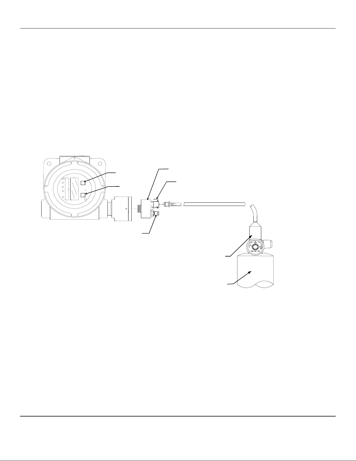
Calibration equipment is available from
ENMET
Corporation to calibrate the
EX-5120
sensor/transmitters. A calibration
adapter will have a fitting for the gas cylinder on one side, and a cover to go over the sensor housing on the other.
Generally, a cylinder of 20.9% Oxygen is used to provide a fresh air reference or Zero point for the calibration. Another
cylinder is used to provide the Span reference point for calibration. Depending on the instrument calibration, the Span gas may
be the same gas that the instrument is calibrated to display, or it may be another gas, which
ENMET
has found to have a similar
response.
Figure 4: Calibration Adapter EX-5120 Sensor/Transmitter
5.2.1 Zero Adjust
A ZERO function should be performed only when the
EX-5120
sensor/transmitter is exposed to fresh air. If the air at the sensor
is in question, use a cylinder of 20.9% oxygen to provide a clean air reference. Attach the cylinder to the calibration adapter.
Enter the maintenance menu by placing the magnet over
MENU
switch for 2 to 4 seconds. See
Figure 5,
EX-5120
Maintenance Menu flow chart.
The second menu available is the Zero.
Tap the
SELECT
switch to perform a Zero.
If the Zero is successful
, Cal OK appears on the display and in 1 – 2 seconds, display will change to Span.
If you wish to Span the sensor Tap the
SELECT
switch you are now ready to apply gas.
Proceed to gas span step 2
If you wish to Exit the maintenance menu, Tap
MENU
switch until Exit is displayed, then tap
SELECT
switch to return to the
instrument Normal Gas Display
If the
Zero is Not successful,
sensor is outside of safe parameters to be zeroed, the display will read Bad Zero. Repeat
Section 5.2.1 Zero Adjust making sure to use a cylinder of 20.9% Oxygen.
Regulator
Gas Cylinder
Select
Menu
Output, for Gas
I
nput, for Calibration
or Optional Gas Sampling
Calibration Cover
EX-5120
ENMET Corporation
10
5.2.2 Gas Span
It is recommended that the Zero Function be performed first.
Enter the maintenance menu. See
Figure 5,
EX-5120
Maintenance Menu flow chart.
1.
Tap the
MENU
switch once to show Span on the display.
2.
Tap the
SELECT
switch to perform a Span procedure. The display will alternate between the calibration gas concentration
and a signal level.
3.
Attach the associated calibration gas cylinder to the regulator and calibration cover. See to
Figure
4
.
4.
Open the valve to apply the calibration gas to the sensor.
5.
Watch for the signal level to stabilize.
6.
Once the signal level has stabilized, the
EX-5120
will automatically lock in the calibration data and:
If the Span is successful, Cal OK appears on the display momentarily, then advances to Alarm 1. Remove calibration gas.
To exit maintenance menu tap the
MENU
switch until Exit appears, then tap the
SELECT
switch.
If the sensor is outside of acceptable parameters, Bad Span is displayed momentarily, then returns to Span.
Remove calibration gas. Tap the
MENU
switch until Exit appears, then tap the
SELECT
switch. Check span gas and
repeat calibration.
NOTE:
Some software revisions require the
SELECT
switch be tapped to accept the signal.
7.
Calibration is complete.
5.2.3 Exit Maintenance Menu
Exit maintenance, by tapping on the
MENU
switch until Exit appears on the display. Tap the
SELECT
switch to return to the
instrument Normal Gas Display.
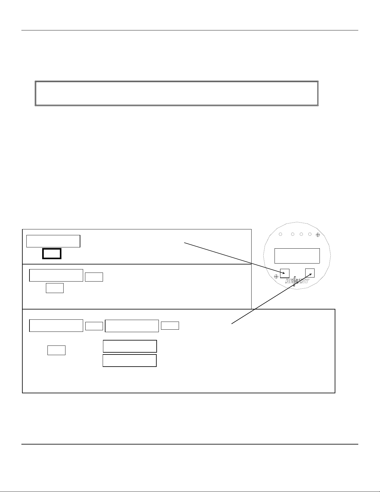
Normal Display Mode
NOTE:
You can change the Calibration Gas Level. H
OLD
the magnet over the S
ELECT
switch for 2 – 4 seconds
The M
ENU
switch changes digit indicated by underscore cursor
The S
ELECT
switch locks underscored digit and moves to next digit
5%
MENU
H
OLD the magnet over the
M
ENU switch for 2 – 4 seconds
to enter the Maintenance Menus
Exit
S
ELECT
Tap the
S
ELECT switch to return to the Normal
Display Mode.
See Section 5.2.3
MENU
Tap the magnet over the MENU switch to cycle through Maintenance Menus
OR
Zero
Cal OK
If
the Zero signal is within Preset Specs the EX-5120 will display
Cal OK, See Section 5.2.1
If the Zero signal is not within Preset Specs the EX-5120 will
display Bad ZERO
NOTE:
Some software revisions require the
SELECT
switch be
tapped to accept the signal.
S
ELECT
MENU
Bad ZERO
PV: 0
S
ELECT
Tap the SELECT switch to initiate Zero adjustment
Select
Menu

EX-5120
ENMET Corporation
11
Figure 5: EX-5120 Maintenance Menu Flow chart
Apply
Calibration Gas until signal value becomes
stable (about 1 to 4 minutes)
See
Figure
4
If cal is good display will indicate OK or Same
If cal is not within preset “range” display will
indicate Bad Sens
MENU
PV: 0
50
Cal OK
Same mV
Bad Sens
S an
S
ELECT
S
ELECT
OR
OR
NOTE: You can change the Calibration Gas Level.
HOLD the magnet over the SELECT switch
The M
ENU
switch changes digit indicated by underscore cursor
The S
ELECT
switch locks underscored digit and moves to next digit
See Section 5.2.2
S
ELECT
mA S an
MENU
S
ELECT
100
To change mA Span set point:
Tap the M
ENU
switch until mA Span is displayed
Tap the S
ELECT
switch to display the set point
The M
ENU
switch changes digit indicated by underscore cursor
The S
ELECT
switch locks underscored digit and moves to next digit
To
return to Normal Gas Display:
Tap MENU switch until EXIT is displayed
Then tap SELECT switch
To change Alarm set points:
Tap Menu switch until Alarm to be changed is displayed
Tap Select switch to display the set point
The M
ENU
switch: changes digit indicated by underscore
cursor
The S
ELECT
switch: locks in the underscored digit and
moves to next digit
If change is not within range display returns to first digit
If change is within range display moves to Set Time Delay
Use M
ENU
and S
ELECT
switches as above to change time
delay. Between 0 and 5 seconds is allowed
If change is within range display moves to next menu
Λ- Indicates increasing alarm
V - Indicates decreasing alarm
SetTD
sec
0
Alarm3
S
ELECT
Λ 50
MENU
SetTDsec
0
Alarm1
MENU
S
ELECT
Λ
10
SetTDsec
0
Alarm2
MENU
S
ELECT
Λ
2
0

EX-5120
ENMET Corporation
12
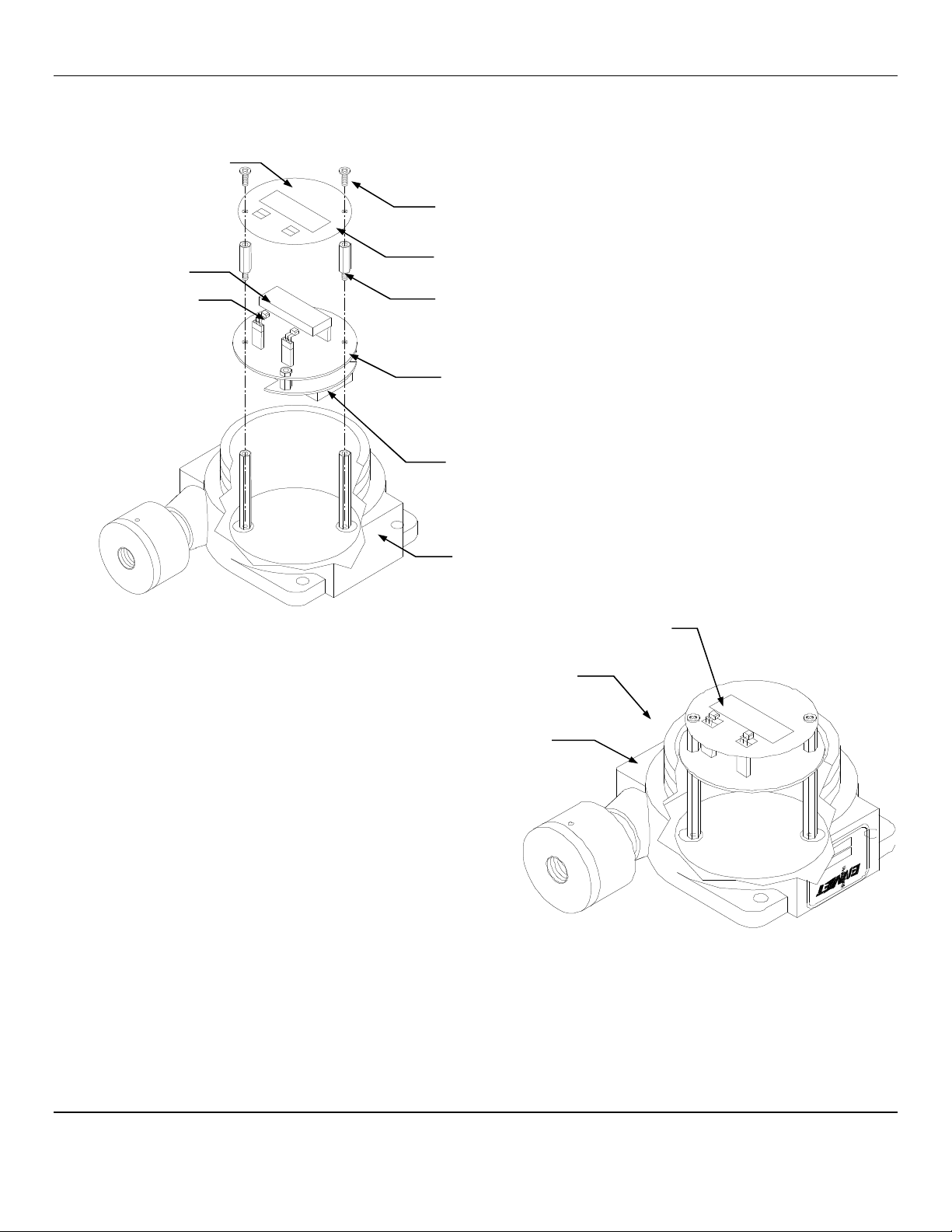
5.3 Sensor Replacement
C
AUTION
:Area must be declassified during sensor replacement.
Sensors should be replaced when they can no longer be calibrated. Replacement sensor part numbers are listed in Section 6.0
of this manual. If you do not know the proper part number for your sensor, be sure to have the
EX-5120
serial number
available when contacting your Distributor or
ENMET
Corporation Technical Support.
To replace a sensor, it is not necessary to open the transmitter housing.
Remove the set screw from sensor housing base.
Unscrew the sensor housing cover and remove Sensor/PC Board Assembly.
NOTE:
Sensor and PC Board are attached and should not be separated from each other.
Plug in new Sensor/PC Board Assembly.
Reassemble the sensor housing.
After the new sensor has been installed, it is suggested to allow the sensor to stabilize for several minutes.
A Factory calibration must be performed.
After entering the Maintenance menu, advance to the Zero menu. Then while viewing the Zero menu, hold the magnet over the
MENU
switch for 2-4 seconds.
After 2-4 seconds, an F will appear on the far right hand side of the display. The F indicates that the instrument is in Factory
mode.
Perform the calibration Zero and Span procedures as outlined in Section 5.2. Be sure that the F is present when selecting the
Zero and Span functions.
The Factory calibration sets a calibration window for future standard instrument calibrations.
Only perform a factory calibration when installing a new sensor!!
Figure 6: Sensor Replacement
Set Screw
(0.050 inch, 1.27mm Hex Key)
Sensor Housing Base
Sensor /P C Board
Assembly
Sensor Housing Cover
EX-5120
ENMET Corporation
13
6.0 eplacement Part Numbers
ENMET
replacement part numbers:
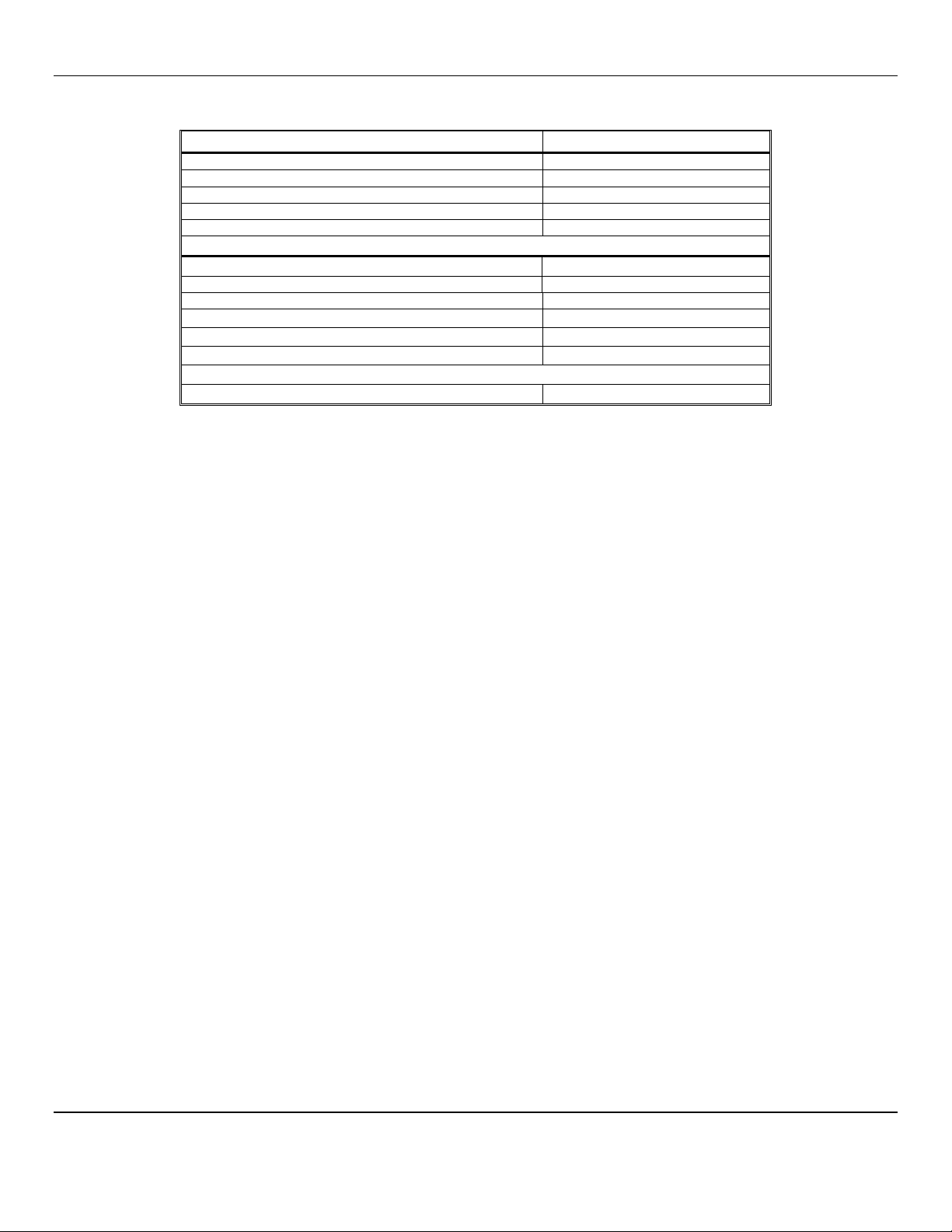
Description Part Number
Sensor, Infrared Methane, 0 – 100% LEL 03056-002
Sensor, Infrared Butane, 0 – 100% LEL 03056-012
Sensor, Infrared Propane, 0 – 100% LEL 03056-008
Consult ENMET Distributor or ENMET Corp for additional ranges
Regulator Assembly, for 17lcylinders 02506-004
Magnet 50030-001
Calibration/Sampling Adapter 03700-034
Calibration Gas, 17lcylinders, 50% LEL Methane 03220-050
Calibration Gas, 17lcylinders, 50% LEL Butane 03282-050
Calibration Gas, 17lcylinders, 50% LEL Propane 03221-050
Consult ENMET Distributor or ENMET Corp for additional gases

EX-5120
ENMET Corporation
14
7.0 WA ANTY
ENMET
warrants new instruments to be free from defects in workmanship and material under normal use for a period of one
year from date of shipment from
ENMET
. The warranty covers both parts and labor excluding instrument calibration and
expendable parts such as calibration gas, filters, batteries, etc... Equipment believed to be defective should be returned to
ENMET
within the warranty period (transportation prepaid) for inspection. If the evaluation by
ENMET
confirms that the
product is defective, it will be repaired or replaced at no charge, within the stated limitations, and returned prepaid to any
location in the United States by the most economical means, e.g. Surface UPS/FedEx Ground. If an expedient means of
transportation is requested during the warranty period, the customer is responsible for the difference between the most
economical means and the expedient mode.
ENMET
shall not be liable for any loss or damage caused by the improper use of
the product. The purchaser indemnifies and saves harmless the company with respect to any loss or damages that may arise
through the use by the purchaser or others of this equipment.
This warranty is expressly given in lieu of all other warranties, either expressed or implied, including that of merchantability,
and all other obligations or liabilities of
ENMET
which may arise in connection with this equipment.
ENMET
neither assumes
nor authorizes any representative or other person to assume for it any obligation or liability other than that which is set forth
herein.
NOTE: When returning an instrument to the factory for service:
Be sure to include paperwork.
A purchase order, return address and telephone number will assist in the expedient repair and return of your unit.
Include any specific instructions.
For warranty service, include date of purchase
If you require an estimate, please contact
ENMET
Corporation.
There are Return for Repair Instructions and Form on the last pages of this manual. This Form can be copied or used as needed.
Manual Part Number
80003-092
October 2008
MCN-426, 10/13/10
MCN-13-011, 12/20/13

PO Box 979
680 Fairfield Court
Ann Arbor, Michigan 48106-0979
734.761.1270 Fax 734.761.3220
Returning an Instrument for Repair
ENMET instruments may be returned to the factory or any one of our Field Service Centers for regular repair
service or calibration. The ENMET Repair Department and Field Service Centers also perform warranty
service work.
When returning an instrument to the factory or service center for service, paperwork must be included which
contains the following information:
A purchase order number or reference number.
A contact name with return address, telephone and fax numbers
Specific instructions regarding desired service or description
of the problems being encountered.
Date of original purchase and copy of packing slip or invoice
for warranty consideration.
If a price estimate is required, please note it accordingly and be
sure to include a fax number.
Providing the above information assists in the expedient repair and return of your unit.
Failure to provide this information can result in processing delays.
ENMET charges a one hour minimum billing for all approved repairs with additional time billed to the closest
tenth of an hour. All instruments sent to ENMET are subject to a minimum evaluation fee, even if returned
unrepaired. Unclaimed instruments that ENMET has received without appropriate paperwork or attempts to
advise repair costs that have been unanswered, after a period of 60 days, may be disposed of or returned
unrepaired COD with the evaluation fee.
Service centers may have different rates or terms. Be sure to contact them for this information.
Repaired instruments are returned by UPS/FedEx Ground and are not insured unless otherwise specified. If
expedited shipping methods or insurance is required, it must be stated in your paperwork.
Note: Warranty of customer installed components.
If a component is purchased and installed in the field, and fails within the warranty term, it can be
returned to ENMET and will be replaced, free of charge, per ENMET’s returned goods procedure.
If the entire instrument is returned to ENMET Corporation with the defective item installed, the item will
be replaced at no cost, but the instrument will be subject to labor charges at half of the standard rate.

Repair Return Form
Mailing Address:
ENMET Corporation
PO Box 979
Ann Arbor, Michigan 48106
Phone Number: 734.761.1270
FAX Number: 734.761.3220
Shipping Addr
ess:
ENMET Corporation
Attn: Repair Department
680 Fairfield Court
Ann Arbor, Michigan 48108
Your Mailing Address:
Your Shipping Address:
Contact Name: __________________________ Your Phone: _______________________
Your PO/Reference Number: _______________ Your FAX: _______________________
Payment Terms: KCOD
(Check one) KVISA / MasterCard______________________ ________ ________
Card number Expiration Card Code
KAmerican Express______________________ ________ ________
Card number Expiration Card Code
Name as it appears on the credit card___________________________________________
Return Shipping Method:
KUPS: KGround K3 Day Select KNext Day Air KND Air Saver K2-Day Air
KUPS Account number: _________________________
KFederal Express: KGround KExpress Saver KP-1 KStandard K2-Day Air
KFedEx Account number: ________________________
Would you like ENMET to insure the return shipment?
KNo KYes Insurance Amount: $_________________
Table of contents
Other ENMET Transmitter manuals


Popular Transmitter manuals by other brands


ENSIM SENSORS
ENSIM SENSORS DX-ELS-tx operating manual

APG
APG PT-500 Series user manual

Evikon
Evikon PluraSens E2608-N2O user manual

Extron electronics
Extron electronics XTP T UWP 202 Setup guide

Radionode
Radionode UA10 quick start guide

VERIS INDUSTRIES, INC.
VERIS INDUSTRIES, INC. AA10 Series installation guide


