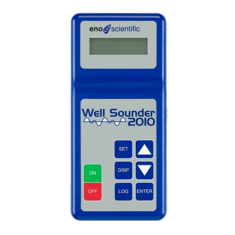
Eno Scientific WELL WATCH 1100 User manual

WELL WATCH 1100
USER MANUAL

Well Watch 1100 User Manual
2
WELL WATCH 1100
USER MANUAL
TABLE OF CONTENTS
PRODUCT OVERVIEW .......................................................................................................... 3
PRODUCT SET UP................................................................................................................ 4
OPERATION.......................................................................................................................... 5
FUNCTION CHARTS.............................................................................................................. 6
MODE DESCRIPTIONS ......................................................................................................... 8
REMOTE OPERATION......................................................................................................... 10
DOWNLOADING DATA ........................................................................................................ 11
INTERPRETATION OF DATA ............................................................................................... 12
ERROR CODES .................................................................................................................. 13
SPECIFICATIONS................................................................................................................ 14
ADDITIONAL NOTES........................................................................................................... 15
WARRANTY AND SERVICE................................................................................................. 15

Well Watch 1100 User Manual
3
PRODUCT OVERVIEW
The Well Watch 1100 is a si ple to use self-contained se i-per anent acoustic ranging instru ent designed specifically to find
the distance through a pipe or bore hole to an obstruction which could be the surface of water in the hole or the dry botto .
The product consists of a control unit and a probe. The control unit contains the driver electronics, processor, display, and
keypad. Internal non-volatile e ory is included to record syste settings, calibration data, and log up to 14,976 data points. A
real-ti e clock/calendar is also included to ti e sta p the recorded log data. The RS232 port can be set to output data to a
re ote device or used as a bidirectional co unications interface to a co puter for re ote progra ing or data download. A
power jack allows the unit to be run fro an optional AC adapter or battery pack.
The probe contains a speaker, a icrophone and te perature sensor in the probe tip. The probe is designed to easily attach to a
standard well cap vent opening while also allowing the display unit to be operated in a convenient location up to 6 feet away.
The Well Watch trans its an acoustic pulse into the pipe, then easures the ti e to the returned echo. The distance is
calculated as the product of the sound speed and the ti e. Since the sound speed has a large te perature dependence, a
te perature sensor is included in the probe to adjust for variations.
Accessories for the Well Watch 1100 can be found on our website at www.wellsounder.co .

Well Watch 1100 User Manual
4
PRODUCT SET UP
Re ove the product fro its case and follow these steps:
CONFIRM POWER SOURCE: The control unit ships fro the factory with the lithiu backup battery installed. To access the
battery, re ove the four screws on the face of the case and open the cover. The unit ay be operated by an AC adapter or
external battery pack attached to the power connector on the botto of the unit. The external power should supply between 7
and 12VDC at 50 a using a type M connector.
CONNECT CONTROL UNIT AND PROBE: Attach the probe plug to the jack on the botto end of the control unit.
ATTACH TO WELL: Attach the probe to the well by inserting the tapered end of the probe into the vent hole in the well cap. If
the well does not have a cap, the well casing can be covered with any flat piece of aterial, i.e. plastic or cardboard, with a s all
hole into which the probe fits snugly. It is not necessary that the probe connection be air tight. The probe will work best when the
probe tip reaches into the well cavity.
The unit is now ready to operate.

Well Watch 1100 User Manual
5
OPERATION
A co plete description of all functions can be found in the Mode Definitions section of this anual.
POWER ON TO DEPTH DISPLAY: The unit will power on when power is supplied to the power connector. The probe will
pulsate and the LCD screen will display the default operating screen. The depth is displayed on the top line. Press the arrow
buttons to view additional infor ation displayed on line two such as the battery voltage, the optional flow eter, or the
te perature sensor.
Note: If error conditions exist, line two of the display will be replaced by an error message. See the ERROR CO ES section for
details.
ACCESS DISPLAY MODE: Press the DISP button to view the data log and the syste date and ti e. While the date and ti e
are displayed, press SET to edit the date and ti e. Use the arrow buttons to adjust the infor ation. Press DISP to return to the
depth reading. Press SET while the depth or log are displayed to cycle through the syste options. Press DISP at any ti e to
return to the depth reading.
ACCESS SET MODE: Press the SET button to view and change any of the syste settings. There are 17 settings. Continue to
press SET to scroll through all of the settings. Press DISP to return to the depth reading.
1. Product Info 2. Unit ID 3. Well Te p
4. Flow Clear 5. Offset 6. Range
7. Alar 8. Logging 9. Log Rate
10. Log Change 11. Du p Log 12. Clear Log
13. RS232 14. Baud Rate 15. Units
16. Power Mode 17. Factory Reset

Well Watch 1100 User Manual
6
SCROLL: Press the Up or Down arrow button to scroll through the infor ation displayed on the LCD screen for both the SET
MODE and DISPLAY MODE.
POWER OFF: Re ove power fro the power connector to turn off the unit. All syste settings as well as the ti e and date,
and log data are aintained while the power is off.
FUNCTION CHARTS
The settings for the DISP MODE and SET MODE are diagra ed in the following charts. A na e in the oval indicates the
button to be pressed on the unit.

Well Watch 1100 User Manual
7

Well Watch 1100 User Manual
8
MODE DESCRIPTIONS
DEPTH DISPLAY –The default display ode after power-up. While this display is active, the unit is operational, sending pulses
and ti ing the echoes. The depth is displayed on the top line and user selectable infor ation is displayed on the second line.
The depth is displayed at every update but ay be erratic until the signal is locked in. Data displayed on the second line can be
changed by pressing the up of down arrow. Data available varies depending on options enabled on each unit. If there are any
error conditions, such as a issing probe, or low battery voltage, an error essage will be displayed on the second line.
DIAGNOSTIC DISPLAY – One of the data options on the DEPTH DISPLAY ode shows the two correlation coefficients: the
signal strength for the trans itted and returned echo signal. In nor al operation the first coefficient will be in the range 10-30 and
be larger than the second. If the second is larger, it ay indicate that the unit is locking on to an erroneous reflection fro a
breakout in the well, or that the top of the well is not closed tight enough. Si ilarly, the first signal strength should be in the range
of roughly 250-400 and the first should be larger than the second. If not, it could indicate that the well is deeper than the range,
excessive noise in the well or a proble with the probe itself.
LOG DISPLAY – The first data display in the DISP MODE, provided that logging is available on the unit, allows the user to
review the logged data. The first data point shown is the last point easured, and displays the sequential nu ber for the point,
the depth reading, and the date and ti e sta p. Other points are displayed by pressing the up or down button. Rapid scrolling
is activated by holding the up or down button.
TIME AND DATE DISPLAY – The second data display in DISP MODE shows the ti e and date on the internal clock. The ti e is
in 24 hour for at. Press the SET button while viewing the ti e to change the syste ti e and date. Press the SET button to
cycle through the ti e and date. Press the DISP button to return to the DEPTH DISPLAY.
PRODUCT TYPE – This SET MODE feature displays the product na e and the software version nu ber. The unit serial nu ber
is displayed by pressing the up or down button.
UNIT ID – This SET MODE feature displays a user selectable ID nu ber in the range 0-255. Set the unit ID nu ber by pressing
the up or down button.
WELL TEMPERATURE – This SET MODE feature is entered by the user to indicate the deep te perature in the well. If you do
not know the well te perature, reference the Water Te perature Data Table found on our website. The te perature near the
surface is auto atically sensed by the probe. These two te peratures are used to calculate the sound speed and in turn, the
distance.
FLOW – This optional SET MODE feature displays the totalized flow, provided the flow sensor is installed and enabled. Pressing
the up or down button resets the totalizer to zero.
OFFSET - This SET MODE feature is a user selectable offset added to each easure ent to adjust to an alternate reference
datu . For exa ple if the well casing extends 18 inches above the ground surface and readings are desired with reference to
the ground level, an offset of -1.5 feet would be entered as the offset.
RANGE – This SET MODE feature sets the pulse rate and in turn the axi u range detectable. A shorter range eans ore
frequent pulses and faster updates.
ALARM – This SET MODE feature allows the user to indicate an alar for a water depth reading that is too high and/or too low.
Press the up or down button to enable or disable either of the two alar s. The high alar is activated if the water level in the well
is higher than the high alar set point. The low alar is activated if the water level is deeper than the low alar set point. An
activated alar displays as an error in the second line of the default display and also as an error code in the RS232 output.
Additionally if the optional alar output is installed, it is also activated.
LOW ALARM SET – If the ALARM is enabled, this SET MODE features allows the user to set the depth at which the low alar is
activated.
HIGH ALARM SET - If the ALARM enabled, this SET MODE feature allows the user to set the depth at which the high alar is
activated.

Well Watch 1100 User Manual
9
MODE DESCRIPTIONS, con’t
LOGGING – This SET MODE feature activates the data logging functionality. Press the up or down button to select the logging
preference. Two logging odes are available: Enable or Change. Enable sets the unit to record data each period. Change sets
the unit to co pare data each period against the last logged data. The new data point is stored in e ory if the easure ent
has changed ore than the log change argin (as defined in the Log Change ode.) The logging function requires that data
pass a consistency check before being accepted as valid data. When the log flag is enabled, a log essage is displayed on the
error line and re ains until valid data is recorded.
LOG RATE – This SET MODE feature deter ines the ti e interval in inutes between logged data points in the range 0 to 60
inutes. Every easure ent is recorded if it is set to zero.
LOG CHANGE – This SET MODE feature is available when logging is set to “change”. This argin deter ines the distance that
the depth ust change to record the new log data. If the new data is within the argin of the last recorded data, then the new
data is discarded.
DUMP LOG RS232 – This SET MODE feature sends all of the logged data to the serial port. Press the up or down button to
send the data. Ensure the cable is connected to the RS232 port.
CLEAR LOG – This SET MODE feature displays the nu ber of data points collected in the log out of the total nu ber of data
points allowed. Press the up or down button to erase all data fro the log and free the e ory for additional logging.
RS232– This SET MODE feature activates the trans ission of data over the serial port. Press the up or down button to ake the
selection. Two serial odes are available: Continuous and Logged Only. When set to Continuous, every easure ent is sent
over the serial port. When Logged Only is selected, data is only sent when it is logged. Trans itted data includes the ti e, date,
and all easured data, and the highest priority error code. Select Off to deactivate this feature.
RS232 BAUD RATE – This SET MODE feature is activated when the RS232 feature is activated. Press the up or down button to
select available serial baud rates. The default is 19,200. The data for at is always 8 bit with 1 stop bit.
UNITS – This SET MODE feature allows the user to select the appropriate easure ent syste for the data. Press the up or
down button to scroll through the options: English for deci al feet, degrees Fahrenheit and gallons; English ft-in for distance
displayed as feet and inches; or Metric for eters, degrees Celsius, and liters.
POWER MODE – This SET MODE feature activates the power save function. Press the up or down button to scroll through the
options: Nor al or Power Save. When logging data and the Power Save function is activated, the unit is shut down between
logging periods. Battery life can be extended by ore than 6 ti es using this function.
FACTORY RESET – This SET MODE feature allows the user return the unit to the default configuration. Press the up or down
button to ake the selection.

Well Watch 1100 User Manual
10
REMOTE OPERATION
Connect the unit to a co puter or other RS232 device using a standard straight through serial cable. A si ple serial to USB
adapter is available to use with laptops without serial ports. Using a standard ter inal e ulator progra such as HyperTer inal
or Tera Ter Pro 2.3 (available for free download), set the port and baud rate. If the unit is in power save ode and shut down,
press a key on the keypad to wake the unit. It will re ain awake for 30 seconds after the last key or RS232 co and. Then
press the return key <return> on the co puter. If it is set up correctly, the unit should respond with a WS2k> pro pt. The unit is
now ready to receive co ands fro the re ote device or co puter.
The re ote co ands are case sensitive and ust be entered exactly as shown on the list below. One co and per line
ter inated by a <return>. Extra tabs or spaces will not be accepted.
Exa ples:
Press "d<return>" to du p the log data to the screen. Open a log file (or capture text) on the ter inal e ulator prior to entering
this co and to record the data on the co puter.
Press "u0<return>" to set english ode or "u2<return>" to set etric.
Press "lp5<return>" to set the logging period to 5 inutes.
Press "t 15:30:00<return>" to set the syste ti e to 3:30 PM.
If serial output is enabled, the pro pt and input will be written over on the screen but the input will still be interpreted correctly. It
ay be easier to disable the serial output while using re ote co ands. Press “s0<return>” to turn off serial reporting and
“s1<return>” to turn in back on when finished.
USER COMMANDS:
In the following list:
[iiii] indicates a para eter of up to a 4 character integer (no deci al point).
[ddddd] indicates up to 5 character deci al nu ber (deci al point optional).
<ret> indicates a return.
a0<ret> alar off
a1<ret> low alar on
a2<ret> high alar on
a3<ret> both alar s on
ah[iiii] <ret> set high alar level
al[iiii] <ret> set low alar level
cX<ret> clear log
d<ret> du p log
f[dddddddddd] <ret> preset flow totalizer
i[iii] <ret> set unit ID
l0<ret> logging off
l1<ret> logging on
l2<ret> log on change
lp[iiii] <ret> logging period inutes
l [dddddd] <ret> log change distance
o[dddddd] <ret> offset to add to all distance easure ents
p0<ret> power saver off
p1<ret> power saver on (CAUTION – while in power down,
RS232 is off and no further co unications will be
accepted)
r[iii] <ret> set ax easure ent range
s0<ret> turn off RS232 reporting
s1<ret> turn on RS232 reporting
s2<ret> turn on RS232 reporting for logged points only

Well Watch 1100 User Manual
11
REMOTE OPERATION, con’t
sb[i] <ret> set baud rate
0 –300
1 – 1200
2 – 2400
3 – 4800
4 – 9600
5 – 14400
6 – 19200
7 – 38400
8 – 57600
t [hh: :ss] <ret> set ti e
td[dd/ /yy] <ret> set date
u0<ret> set english units (ft)
u1<ret> set english units (ft in)
u2<ret> set etric units
w[dddddd] <ret> set well te perature
Ca[dddddd] <ret> calibrate te p sensor 1
Cb[dddddd] <ret> calibrate te p sensor 2
Cc[dddddd] <ret> calibrate te p sensor 3
Cd[dddddd] <ret> calibrate battery sensor
?<return> send a list of the current settings
<return> send current data
Most of these co ands are the sa e as those described under Mode Definitions. There are, however, a couple additional
functions.
The calibrate co ands allow the user to calibrate the unit for use with a particular probe. Each probe is slightly different, so
while the unit is easuring a te perature, for exa ple, the co and “Ca73.1<ret>” could be entered. This would cause the unit
to recalibrate so that it would currently read 73.1 degrees.
The flow co and allows the user to preset the flow totalizer with up to a ten digit deci al nu ber.
DOWNLOADING DATA
The procedure for collecting data fro field installed logging units in power save ode should be as follows:
1 – Connect the laptop co puter to the unit using a serial cable.
2 – Start a ter inal e ulator progra such as HyperTer or Tera Ter Pro 2.3
3 – Set the Co Port (usually Co 1), and the data for at to 19200 baud, 8 bit, 1 stop bit, parity none and flow control to none.
4 - .Press the “SET” button on the unit to wake it up. There should be a single click.
5 – Press <enter> on the co puter, and the unit should respond with a line of data and a WS2k> pro pt. If not, press again.
6 – If the unit is sending continuous lines of data, press “s0<return>” to turn it off.
7 – Open a log file in the ter inal e ulator.
In HyperTer , click on the “transfer” drop down enu and select “capture text”.
Enter a file na e and click open. A log indicator will light up at the botto of the screen.
When finished, go back to the “capture text” enu and select “stop”.
In Tera Ter Pro 2.3, click on the “file” drop down enu and select “log..”.
Enter a file na e and click open. A log file progra bar will be added at the botto of the screen.
When finished, open this progra bar and click “close”.
8 – Press “?<enter>” on the keyboard if desired to include the unit infor ation in the log.
9 – Press “d<enter>” on the keyboard to start the download. The last data line will be followed by END.
10 – Close the log file as described in ite 7.
11 – Press “cX” to clear the data log to ake roo for additional data logging.
12 – Disconnect co puter. In 30 seconds, the unit should go back to sleep and resu e logging.

Well Watch 1100 User Manual
12
INTERPRETATION OF DATA
DATA QUERY
A si ple <return> sent to the unit instructs the unit to send the current data set. Each data ele ent is preceded by an upper case
letter for the identity of the following nu ber as follow: data, ti e, D depth, other data, B battery voltage and the R error code.
(see the error code section for codes).
Other data includes any enabled options which are reporting valid data. This ay include the T probe te perature, X external
te perature, and F flow.
Exa ple:
WS2k >
2008/07/21 10:12:06 D 74.45 T 76.4 F 0.00 B 5.97 R 2
WS2k >
This indicates that the depth is 74.45 feet, the probe te p is 76.4 F, the flow is 0 gal, the battery voltage is 5.97, and the error
code is 2 eaning that the battery voltage is low.
SYSTEM STATE
A "?" co and sent to the unit instructs it to send its current operating state. This will include 3 lines of data. The first line
reports the odel nu ber and features, the software version, the unit serial nu ber, and the user set ID nu ber. The second
and third lines report the applicable syste settings prefixed by the co ands used to set the as listed in the table in the
section on external co ands. In addition to the settings is the log e ory state prefixed with "ls" and includes the nu ber of
log points in e ory/ total nu ber available. So in the following exa ple 168 points have been used out of 14975.
Exa ple:
WS2k > ?
Mod #WS1100-1023 Ver # 1018 Ser #080628015 ID #001
t2008/07/21 10:12:33 l0 lp15 l 0.30 s0 r 700.00 o 0.00 p0 u0
ls 168/14975 a0 al 100.00 ah 100.00 w 60.5
WS2k >
In this exa ple, "l0" indicates that logging is turned off, "lp15" indicates that the logging period is 15 inutes, and the well
te perature is set to 60.5 degrees.
DATA DUMP
The "d" co and instructs the unit to send the contents of the data log. The infor ation is sent one data point per line and is
for atted like the data query with the exception that there is no error code.
Exa ple:
WS2k > d
Log Du p
2008/07/03 11:28:26 D 120.33 F 0.00 B12.84
2008/07/03 11:34:35 D 120.27 F 0.00 B12.84
2008/07/03 11:47:55 D 120.27 F 0.00 B12.84
2008/07/03 12:03:46 D 120.21 F 0.00 B12.84
End
WS2k >

Well Watch 1100 User Manual
13
ERROR CODES
1 No probe The unit does not see the te perature sensor in the probe.
2 Low Battery The input voltage has dropped below 6.5V. The unit will continue to
function properly until the voltage reaches about 5.4V. Once the battery
voltage reaches 6.5V there is less than 10% battery life re aining
3 FP An internal processor over run is occurring. May indicate an internal fault.
5 CC An internal processor over run is occurring. May indicate an internal fault.
6 Log Full Indicates that the internal log e ory has been filled and no additional
logging will be perfor ed. The log e ory ust be cleared to continue.
7 RS232 over run The co and line reached the end of the buffer without identifying a
co and.
8 Probe Error Indicates that the signal levels received fro the probe are outside the
nor al range. This could be caused by a probe not installed in a well,
excessive noise, or a faulty probe.
9 Low Level Alar Indicates that the well water level has dropped below the low alar set
point. The alar will continue until the level increases, the alar is
disabled, or the set point is changed.
10 High Level Alar Indicates that the well water level has increased above the high alar set
point. The alar will continue until the level decreases, the alar is
disabled, or the set point is changed.

Well Watch 1100 User Manual
14
SPECIFICATIONS
POWER:
External Power – 5.5 to 12VDC at 50 a. Do not exceed 16V. Connector 5.5 x 2.1 center post positive.
Real ti e clock – Li Ion 3V battery CR2032.
MEASUREMENT:
Resolution - .05 ft
Accuracy - .1 ft, (see notes)
Range – 9 to 700 feet.
LOGGING:
Me ory – nonvolatile flash e ory for 14976 data points in addition to calibration and user data.
Logging rates – 1 sec to 60 inutes per sa ple.
ENVIRONMENTAL:
Te perature – -10 to 110 F
Hu idity – 10 to 90% non-condensing.
PHYSICAL:
Di ensions – 4x5x2.5”
Control Unit Weight - ~10.5 oz
Probe Weight - ~5.5 oz
FEATURES:
Display – 2x16 character LCD
Te perature co pensation – in probe
Alar s – high and low 10 to 700 ft.
Serial Output – baud 300 – 57600, 8 data bits, one stop bit. (19200 baud default).
INPUTS:
Acoustic probe
Flow eter input (with adapter) – pulse counting.
Te perature sensor input
Serial port
OUTPUTS:
Serial port
Alar

Well Watch 1100 User Manual
15
ADDITIONAL NOTES
The specified accuracy is achieved provided certain conditions are et. Since the distance calculation is deter ined by ti ing
the returned echo, it is i portant that a free path is available for the pulse to travel to the water surface and return. It is possible
that an obstruction such as torque arrester or centering ring on a pu p pipe can cause a pre ature echo. It is also possible that
a breakout or large fracture opening can also cause a false echo. Ordinary pu p piping and wiring will not interfere with the
easure ents.
The accuracy is also dependent on the sound speed in the well. Since the sound speed is deter ined by the te perature, the
average te perature ust be specified correctly. The error is approxi ately .1%/°F.
The axi u range is li ited by the axi u ti e during which the echo is onitored, and the strength of the echo signal.
Uncased wells drilled through very porous aterial can attenuate the signal faster than the rated distance.
WARRANTY AND SERVICE
Eno Scientific warrants to the user that all products anufactured by Eno Scientific, will be free fro defects in work anship and
aterials for 1 year fro the date of ship ent.
Eno Scientific warrants to repair or replace any such defective equip ent or part (deter ined to our satisfaction to have a defect
in work anship or original aterial) upon receipt and inspection of such defective equip ent to Eno Scientific with all shipping
pre paid by the user.
In no event shall Eno Scientific be liable for any direct, indirect or consequential da ages, abuse, acts of third parties (rental
equip ent), environ ental conditions or other expenses which ay arise in connection with such defective equip ent. This
warranty shall not apply to da age of equip ent caused by incorrect installation, usage, storage alteration or inadequate care.
This warranty does not apply to parts, asse blies or devices not anufactured by Eno Scientific which are covered by other
anufacturers’ warranties. There are no warranties except as specifically provided in writing herein.
Contact Eno Scientific with any warranty or service questions.
For additional infor ation, please visit our website at www.wellsounder.co .
Table of contents
Other Eno Scientific Measuring Instrument manuals