Eno Scientific Well Watch 700 User manual
Eno Scientific Well Watch 700 Page 1

Eno Scientific
PO Box 1586
Hillsborough, NC 27278
USA
www.enoscientific.com
910-778-2660
Copyright Notice
Copyright © 2017 Eno Scientific, Hillsborough, NC 27278, USA.
All rights reserved.
Part number: 700-901
Eno Scientific Well Watch 700 Page 2

WELL WATCH 700
USER MANUAL
TABLE OF CONTENTS
PRODUCT OVERVIEW...................................................................................4
QUICK START GUIDE....................................................................................5
CAUTIONS........................................................................................................7
BACKGROUND – HOW IT WORKS..............................................................9
INSTALLATION.............................................................................................11
SET UP.............................................................................................................14
LOGGING........................................................................................................23
USB COMMUNICATIONS............................................................................24
ANALOG OUTPUT.........................................................................................25
RS232 COMMUNICATIONS.........................................................................26
REMOTE SERIAL OPERATION OVER RS232...........................................27
INTERPRETATION OF SERIAL DATA.......................................................29
MODBUS COMMUNICATIONS...................................................................30
MAINTENANCE.............................................................................................35
FREQUENTLY ASKED QUESTIONS..........................................................36
Appendix A: UPDATE RATES......................................................................38
Appendix B: BAUD RATES..........................................................................39
SPECIFICATIONS..........................................................................................43
ADDITIONAL NOTES...................................................................................44
WARRANTY AND SERVICE........................................................................45
Eno Scientific Well Watch 700 Page 3
PRODUCT OVERVIEW
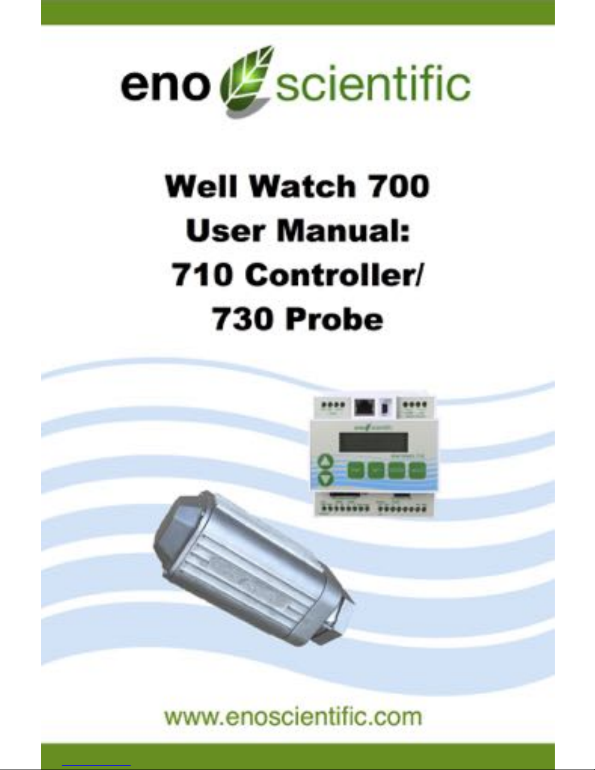
The Well Watch 700 is a simple to use self-contained acoustic ranging instrument
designed specifically to find the distance through a closed pipe (well casing or
sounding tube as small as 1/2”) from one closed end to the to the other. The Well
Watch works by sending a low frequency sound pulse into the pipe, then measuring
the time it takes for the echo to return from the opposite end, which could be a plug or
water surface. The distance is calculated using the sound speed and the time. The low
frequency sound can follow the pipe around corners and in any direction up/down or
horizontally. It can be used to measure any closed pipe, straight or crooked with a
constant diameter.
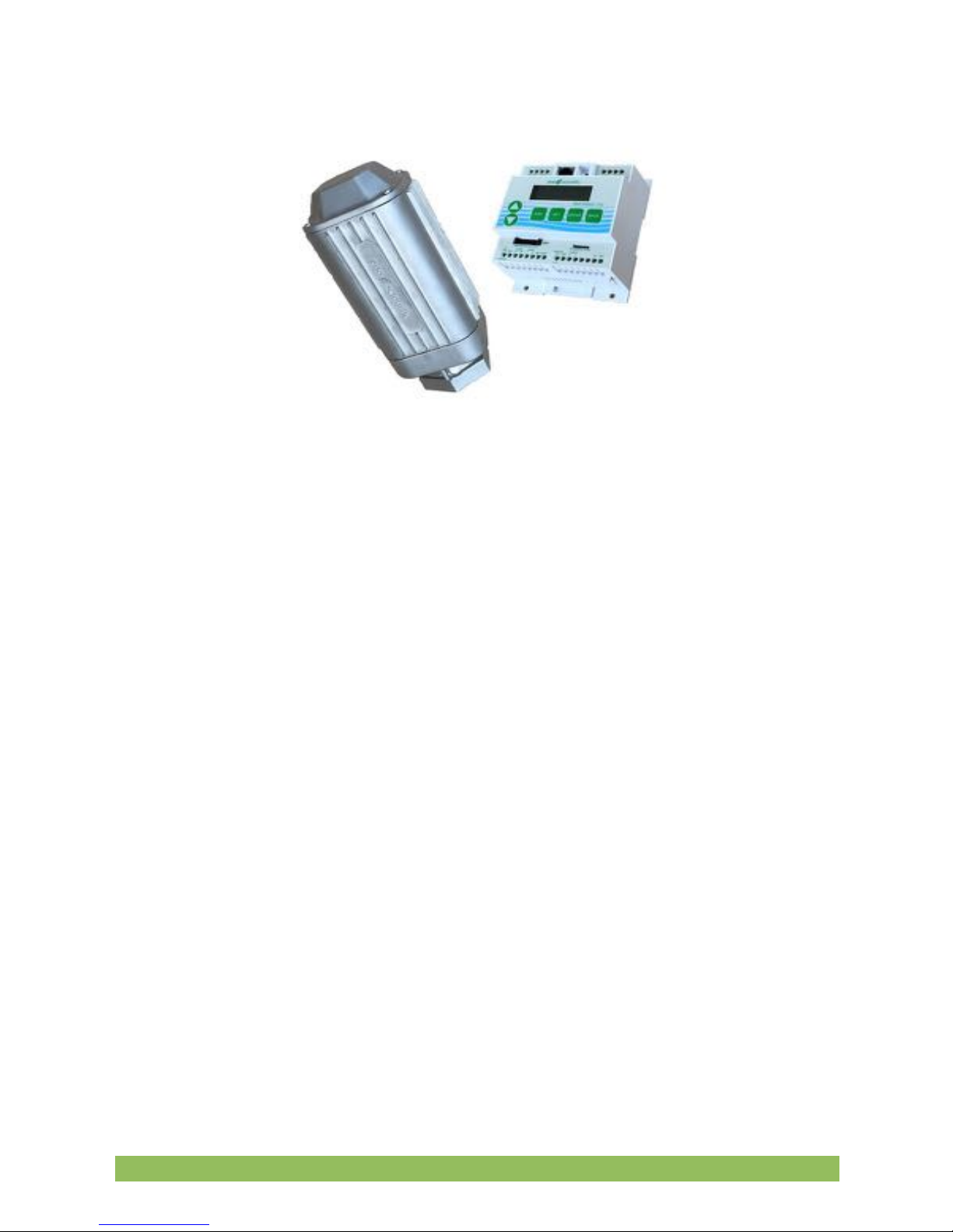
The Well Watch 700 consists of a model 710 control unit and a model 730 smart probe
which are which are interconnected by a 4 conductor cable. The 710 controller
contains the driver electronics, processor, data logger, display, and keypad, while the
smart probe contains a second processor, drive electronics, speaker, a microphone
and a threaded spout to connect to the test pipe.
When the unit powers, it immediately begins sending sound pulses into the well and
attempts to characterize the well. After a few seconds, the depth is calculated and
output for the user. Data can be output in a variety of formats through the several
outputs provided. The controller requires 12-36 vdc external power. The probe is
powered by the controller through the 4 conductor interconnect cable.
Eno Scientific Well Watch 700 Page 4

QUICK START GUIDE
The Well Watch is nearly ready to go right out of the box. Follow the few steps below to
find the depth to water. If depth to the water is all you are interested in, then this is all
you need to read. To learn about the more advanced features continue reading the
operation section of this manual.
1.
Mount Probe to Well. Connect the threaded end of the probe to a well
access port. A reducing bushing down to as little as 1/2” can be used if
necessary, however it is better to use as big as possible up to 2”. The probe
is heavy and may require additional support if connected to the well with a
small or flexible tube. The well casing must be closed for the Well Watch to
perform correctly. (See Setup in the manual if this is an issue.)
2.
Mount Controller. Mount the controller in a protected area. It is not weather
proof. It can be mounted using the screw flange or to a DIN rail.
3.
Connect the Controller to the Probe. It is recommended that 1/2” flexible
liquid tight conduit be used between the probe and controller area to prevent
damage and moisture intrusion. However, a moisture tight strain relief may
also be used. Connect the four conductor cable between the probe and 4
probe terminals on the controller matching pin for pin.
4.
Connect Power to the controller. Connect the power source to the Ext Pwr
terminal and adjacent GND terminal. The unit requires 12 to 36 VDC at a
peak load of 150 ma.
5.
Turn meter on. Apply power to turn the meter on. You should see the
display show the product name and hear a popping sound coming from the
probe.
6.
Measure well. After the unit characterizes the well, the measured depth will
Eno Scientific Well Watch 700 Page 5

be displayed on the screen. If the measured distance is not as expected,
then proceed to the next step to change the initial settings.
7.
Change initial settings. Press the SET button once to enter the settings
mode. Press the UP or DOWN button to scroll through the available settings.
To change a setting, press ENTER to start the number flashing, press the UP
or DOWN button to change as desired, then press ENTER to enter the new
setting and stop the flashing. Press the UP or DOWN button to continue to
scroll through the other available settings. Press DISP at any time to return to
read the measured depth. For best depth results, the Range Min, Range
Max, and the Well Temperature should all be set.
8. Read
other information. While reading the depth display, press the UP or DOWN
buttons to read other information.
We encourage you to read the frequently asked questions section. They really are
frequently asked. Also, visit our website www.enoscientific.com for the latest manual
and installation tips.
Eno Scientific Well Watch 700 Page 6

CAUTIONS
The Well Watch 710 Controller is not water proof!
The controller is designed to be housed in a weather proof shelter. A gasketed
enclosure or well shelter are desired.
Sudden application of well pressure may damage the probe!
The 730 Probe was designed to be used on wells under pressure up to 100 psi.
However, when first connecting the probe to pressure, allow pressure to build slowly (1
psi/second) would be desirable.
External power cannot exceed 36 volts DC!
When supplying external power to the Well Watch, care must be taken to insure that
voltage spikes or induced transients are not conducted into the unit. Over voltage and
surge protectors and proper grounding should be used if this is a possibility.
Use surge suppressors and grounding on signal lines!
When connecting the Well Watch to remote equipment through the RS232 port or
analog outputs, care is required to prevent ground loops, lightning induced transients
etc from reaching the Well Watch. Over voltage and surge protectors and proper
grounding should be used if this is a possibility.
FCC Warning Statement.
THIS DEVICE COMPLIES WITH PART 15 OF THE FCC RULES. OPERATION IS
SUBJECT TO THE FOLLOWING TWO CONDITIONS: (1) THIS DEVICE MAY NOT
CAUSE HARMFUL INTERFERENCE, AND (2) THIS DEVICE MUST ACCEPT ANY
INTERFERENCE RECEIVED, INCLUDING INTERFERENCE THAT MAY CAUSE
UNDESIRED OPERATION.
NOTE: THE GRANTEE IS NOT RESPONSIBLE FOR ANY CHANGES OR
MODIFICATIONS NOT EXPRESSLY APPROVED BY THE PARTY RESPONSIBLE
FOR COMPLIANCE. SUCH MODIFICATIONS COULD VOID THE USER’S
AUTHORITY TO OPERATE THE EQUIPMENT.
Eno Scientific Well Watch 700 Page 7

Industry Canada.
This device complies with Industry Canada license-exempt RSS standard(s). Operation
is subject to the following two conditions: (1) this device may not cause interference,
and (2) this device must accept any interference, including interference that may cause
undesired operation of the device.
Le pre !sent appareil est conforme aux CNR d'Industrie Canada applicables aux
appareils radio exempts de licence. L'exploitation est autorise !e aux deux conditions
suivantes : (1) l'appareil ne doit pas produire de brouillage, et (2) l'utilisateur de
l'appareil doit accepter tout brouillage radioe !lectrique subi, me "me si le brouillage est
susceptible d'en compromettre le fonctionnement.
Under Industry Canada regulations, this radio transmitter may only operate using an
antenna of a type and maximum (or lesser) gain approved for the transmitter by
Industry Canada. To reduce potential radio interference to other users, the antenna
type and its gain should be so chosen that the equivalent isotropically radiated power
(e.i.r.p.) is not more than that necessary for successful communication.
Conforme !ment a # la re !glementation d'Industrie Canada, le pre !sent e !metteur radio
peut fonctionner avec une antenne d'un type et d'un gain maximal (ou infe !rieur)
approuve ! pour l'e !metteur par Industrie Canada. Dans le but de re !duire les risques
de brouillage radioe !lectrique a # l'intention des autres utilisateurs, il faut choisir le type
d'antenne et son gain de sorte que la puissance isotrope rayonne !e quivalente (p.i.r.e.)
ne de !passepas l'intensite ! ne !cessaire a # l'e !tablissement d'une communication
satisfaisante.
Eno Scientific Well Watch 700 Page 8

BACKGROUND – HOW IT WORKS
The Well Watch 700 works by pushing an air pressure wave or low frequency sound
wave into the well. For this reason, it is important that the probe be connected to a
closed end of the pipe to prevent the air pressure from just escaping the open end.
After the Well Watch sends its sound pulse, it listens for the pulse to return. Since
sound travels at a predictable rate, the Well Watch can calculate where in the well the
pulse was reflected by timing the returning pulse.
The pressure wave generated by the probe will continue to travel into the well until
something disturbs it. Every imperfection in the well will disturb the wave, and every
time it is disturbed, some of the wave changes direction and is reflected back to the
Well Watch leaving the main wave a little weaker. A complete obstruction like the
surface of the water, reflects the entire remaining wave. Most common obstructions like
wires and tubes and pipe couplings do not reflect enough of the wave to cause a
Eno Scientific Well Watch 700 Page 9

problem, provided that the remaining part of the main wave is relatively big enough to
be obviously the one of interest.
Some imperfections like a change in casing diameter can cause a significant part of the
wave to be reflected. Where the water may be very far away and its reflected pulse
very weak, the reflection from the imperfection could be the largest wave returning to
the Well Watch. In this case, the Well Watch would lock in on the erroneous reflection
and tell you that the water was at the end of the casing. The Well Watch therefore
offers settings to limit the range in which it will look for reflections. If for example the
casing in your well ended at 40 feet and the water was around 80 feet, then the
minimum range could be set to 60 feet so that the Well Watch would ignore any
reflection from the casing.
The sound wave traveling through the well also loses energy as it travels, more as the
surface of the well casing gets rough or porous. To compensate for this, the Well
Watch increases its gain with time to listen for fainter signals. This can cause problems
if the Well Watch listens for too long. The gain will get so high that the pump noise or
even noise from outside the well will outweigh the desired pulse. Therefore, the
maximum range setting is available to tell the Well Watch how long to listen. If for
example the pump is mounted at 200 feet, then there is no reason to set any more than
250 ft as a maximum range.
The strength of the sound pulse generated by the probe depends on how much space
it needs to fill. A 12” pipe is 4 times larger than a 6” pipe in volume and therefore the
pulse will be 4 times smaller. A weaker pulse becomes more susceptible to pump noise
and loss with depth. While the Well Watch is being used in wells up to 30”, many of
these installations do not get reliable results with running pumps etc. These wells
usually require a sounding tube installed in the well which reaches into the water and
provides a tight connection to the probe at the top. A 3/4” or 1” tube is adequate.
Something to keep in mind, especially for shallow wells, is that the sound wave
bounces off the top and bottom of the well. So it is possible for the pulse to bounce
back and forth many times. In a well where the water level is at 6 feet, the Well Watch
would hear a reflection at 6 feet, then again at 12 feet, then 18 etc, until the pulse gets
weak enough to ignore. In this example, you would be able to see the multiple
reflections by increasing the min range. When set to 9ft, the depth would read 12.
When set to 14ft, it would read 18 etc. In this case, it may be helpful to leave a small
leak at the probe to help dissipate the pulse.
Eno Scientific Well Watch 700 Page 10
INSTALLATION
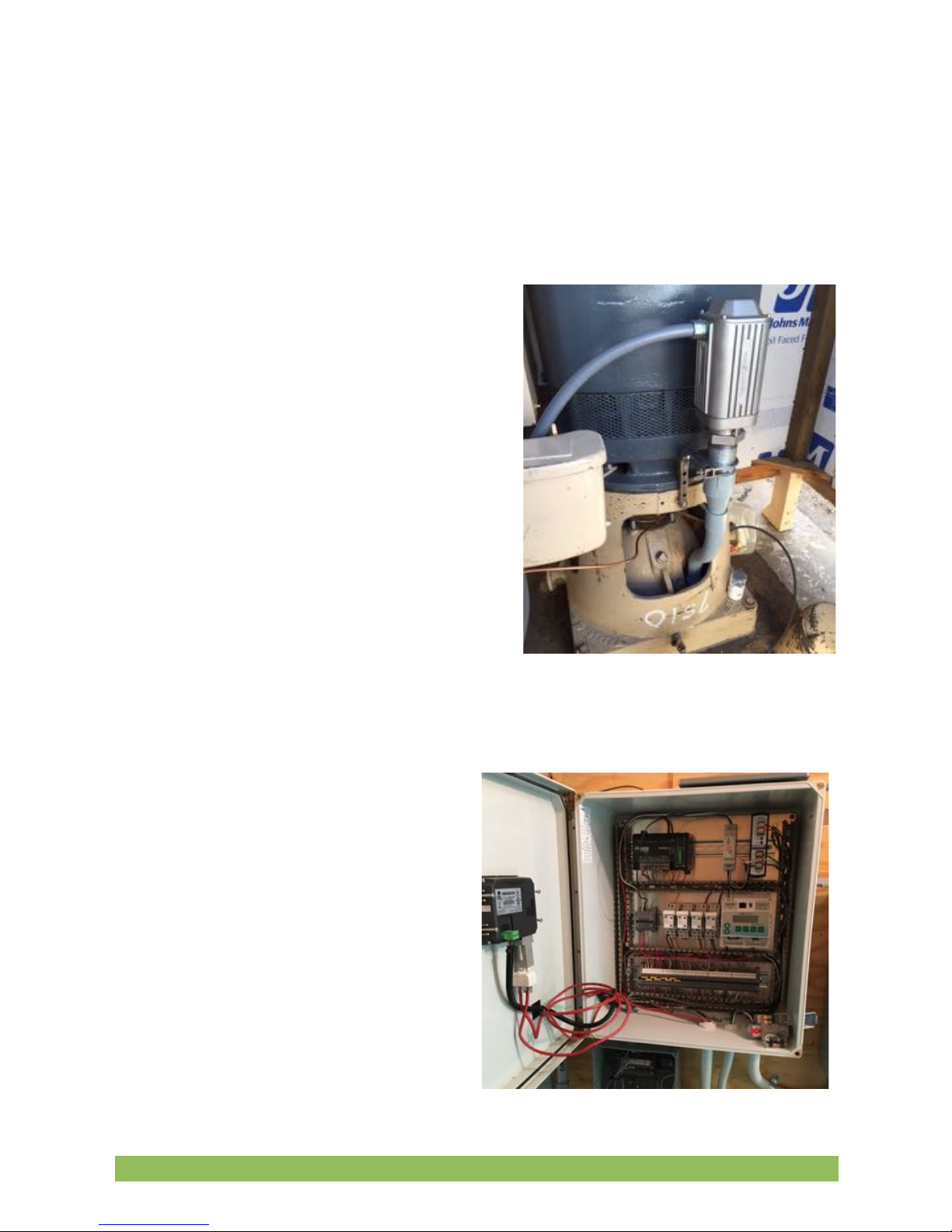
1.
Mount Probe to Well. Connect the threaded end of the probe to a well
access port. A reducing bushing down to as little as 1/2” can be used if
necessary, however it is better to use as big as possible up to 2”. The well
watch pushes air pressure waves
into the well. It is therefore
important that the connection to
the well and top of the well be
closed to air to prevent the air
pressure from escaping and for the
Well Watch to perform correctly. It
is best to install the probe mostly
vertical with the wire connection
toward the lower side to prevent
any water leakage past a poor
seal. Also keep in mind that the
probe is heavy and may require
additional support if connected to
the well with a small or flexible
tube.
2.
Mount Controller. Mount the
controller in a protected area.
It is not weather proof and will
suffer damage if exposed to
the elements. It can be
mounted in any orientation
using the screw flange or to a
DIN rail where access to the
keypad and visibility of the
display can be achieved.
Eno Scientific Well Watch 700 Page 11
3.
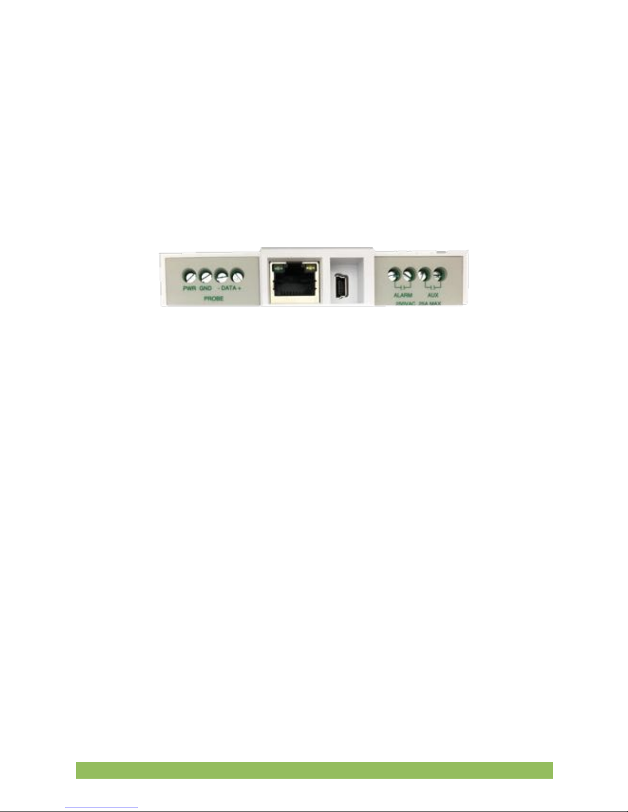
Connect the Controller to the Probe. Four wires are required to connect
the probe to the controller. Any gauge wire from #18 to #28 can be used. A 4
conductor direct bury cable is usually adequate, or if conduit is used ethernet
wire is sufficient. 1/2” flexible liquid tight conduit is recommended between
the probe and controller area to prevent damage and moisture intrusion.
However, a moisture tight strain relief with the direct bury cable may also be
used. Connect the four conductor cable between the probe and 4 probe
terminals on the controller matching pin for pin.
4.
Connect Power to the controller. Connect the power source to the Ext Pwr
terminal and adjacent GND terminal. The unit requires 12 to 36 VDC at a
peak load of 150 ma. GND on the controller refers to the signal ground and
power supply negative, not earth ground.
5.
Connect Outputs from the controller. The controller offers several options
for data and control outputs.
There are two independently programmable relay outputs which have a UL
rating for 30 VDC, 2 A (resistive), or 110 VDC, 0.3 A (resistive) , or 125 VAC,
0.5 A (resistive). These outputs can be used for a remote alarm or control
signal to a pump controller. The outputs are not sufficient to run a pump or
possibly a contactor directly.
Eno Scientific Well Watch 700 Page 12

There are 3 available serial output options of which one can be software
selected at a time. RS232, RS485 Modbus, and SDI-12.
RS232 – 3 wires are required to connect the RS232 port to another device
such as a PC with a 9 pin D connector. The TX terminal on the well watch
connects to pin 2 of the D connector, RX to pin 3, and GND to pin 5.
RS485 - 3 wires are required to connect the RS485 port to a Modbus bus.
The A line, the B line, and the shield to the GND terminal.
SDI-12 - 2 wires are required to connect the SDI-12 port to an SDI-12 bus,
the SDI-12 line, and the shield to the GND terminal.
There are 2 analog outputs, 0-5V and 4-20mA. These outputs are available
concurrently and are independently programmable. The 0-5V output can
source up to 15mA and requires and requires one wire for the output as well
as a ground wire or common ground with the destination device.
The 4-20mA output acts as a throttle valve for an applied voltage and is
isolated so that the device power can be used to power the current loop. In
this case a jumper from the ext pwr terminal to 4-20mA+ will power the loop,
and 4-20mA- will act as a source for output current to the target device. This
also requires either a ground wire or common ground with the target device.
Eno Scientific Well Watch 700 Page 13

Last is the input for a pulsed flow meter. This input requires a signal wire and
a ground wire. The input is designed to accept an input from a flow meter
that provides either a switch closure or a TTL level pulse.
6.
Turn meter on. Apply power to turn the meter on. You should see the
display show the product name and hear a popping sound coming from the
probe. The Well Watch is now ready to run.
SET UP
POWER ON: Apply power to start the Well Watch. The probe will pulsate and the
LCD screen will display a product information screen for a few seconds then go to the
default DISPLAY mode screen. The depth is displayed on the top line once the unit
adjusts to the well and calculates a stable reading. While the unit adjusts to the well the
display will read “DEPTH SEARCHING.”
Eno Scientific Well Watch 700 Page 14

Note: If error conditions exist, line two of the display will be replaced by an alternating
error message. See the ERROR CODES section for details.
The Well Watch has two different operating modes, DISPLAY mode and SET modes.
The DISPLAY modes are accessed by pressing the DISP button, then the UP and
DOWN keys cycle through the available display options. The SET modes are accessed
by pressing the SET button, then the UP and DOWN keys cycle through the available
setting options. When a parameter is shown, pressing the ENT key causes it to flash,
during which time the UP and DOWN keys change the parameter. Press ENT again or
BACK to stop the flashing and return to scrolling through the setting options.
*The DISP key will always return the display to the first display option and the SET key
will always return to the first setting option.
**If left on a set screen, the system will return to the first display screen automatically
after 30 seconds of inactivity.
DISPLAY MODES: There are several DISPLAY options as follow:
1 – DEFAULT display screen which shows current water level with the
time/date on the second line. Once the signal is locked and stable, the depth is
displayed in the units selected. Occasionally a spurious depth reading will be
calculated due to random noise in the well. Software in the Well Watch identifies the
anomaly and holds the last good data through a few bad data points while a good
depth is obtained. An asterisk is displayed before the depth while holding. If a stable
depth is not found in several tries, the depth is replaced with “searching” until one can
be found. If there are any error conditions, such as when the probe is not on the well,
or when the external power supply is low, an error message will alternately be
displayed on the second line.
2 – Flow Meter display screen if the flow meter is enabled, shows the current
flow rate with the totalized flow on the second line. Pressing ENT while on this screen
will reset the flow total to 0.
3 – WIW display screen which shows the total reserve of water in the well
with the rate of change on the second line. The WIW (water-in-well) is calculated using
the set well diameter and the set depth of well. These settings are only used for this
calculation. If the well depth is set to the level of the pump, the WIW number will be the
number of usable gallons (liters) of water in the well.
4 – TIME AND DATA display screen which shows the system time and date.
Pressing ENT while on this screen allows the time and date to be set. Each time ENT
Eno Scientific Well Watch 700 Page 15

is pressed, the next number will flash, showing which number is to be changed. Press
BACK or DISP any time to return to normal operation.
SET MODES: Press the SET button at any time to select the first SET option then
UP or DOWN to show the available settings. While viewing a SET screen, press the
ENT key to select the value for change and cause it to flash. While the value flashes,
press the UP or DOWN button to change the value. Rapid scrolling is activated by
holding the up or down button for about a second. Scrolling gets faster and faster while
the button is held down. The button can be released briefly then repressed to resume
change at the high speed. If the button is released, the scroll rate will be decreased at
the same rate that it increased. When the value is as desired, press the ENT or BACK
button to allow scrolling to the other settings or press the DISP button to return to
normal operation. The new settings are saved automatically as they are changed so
there is no need to press ENTER.
There are several setting options as follow:
CONTROLLER PRODUCT INFO – displays the controller product type, configuration
and the software version number. The unit serial number is displayed by pressing the
ENT button. Press ENT or BACK to return to scroll settings.
PROBE PRODUCT INFO – displays the probe product type, configuration and the
software version number. The unit serial number is displayed by pressing the ENT
button. These numbers will all be zero if the controller is not communicating with the
probe. Press ENT or BACK to return to scroll settings.
UNIT ID – sets a user selectable ID number in the range 0-255 to identify the source of
logged data. The default is 0.
PROBE ENABLE – if advance scheduling is enabled allows the user to disable the
probe and use for example, the flow meter only. The default is ENABLED.
UPDATE RATE – selects the time interval for sounding by the probe. Setting to 0
causes continuous sounding. The default is 0.
Eno Scientific Well Watch 700 Page 16

REFERENCE LEVEL – THIS IS IMPORTANT! All depth measurements by the Well
Watch will be displayed with reference to this reference level. Positive numbers are
higher than the reference level into the sky, and negative numbers are below the
reference level into the earth. The default reference level is 0, meaning that all reported
depths are from the Well Watch. It is common to set the reference level to the level of
the pump (for example -550ft), so that numbers will be positive feet (meters) above the
pump. When this number is changed all other settings and readouts will be changed
accordingly.
Eno Scientific Well Watch 700 Page 17

LEVEL MAX – sets the highest level ( with respect to the reference level) at which the
Well Watch will start looking for the surface of the water. This is used where there may
be a known defect in the well such as a step down in bore diameter. This kind of defect
will reflect some of the pulse which could compete with the desired reflection from the
water surface. If for example this transition occurred at 42 feet, then set the range min
to 50 feet or more to ignore this erroneous reflection.
LEVEL MIN– sets the lowest level (with respect to the reference level) at which the
Well Watch will continue to look for the surface of the water. A shorter range means
more frequent pulses and faster updates. A longer range gives less frequent updates
and increases the possibility of collection spurious noise. This should be set just
beyond the lowest level expected.
WELL TEMP – sets the average air temperature in the well. If you do not know the well
temperature, reference the Water Temperature chart below. It is also usually very close
to the water temperature. This temperature is used to calculate the sound speed and in
turn, the distance. The distance error is fairly small for variations in temperature, about
1% (1 ft per 100 ft) for a 10 ºF (5.6 ºC) temperature error.
Eno Scientific Well Watch 700 Page 18

METHANE – sets the concentration of methane mixed with the air in the well. Sound
travels through methane much faster than through air. The concentration set here is
used to calculate the sound speed and correct for this error. The Well Watch does not
measure methane but can be used to estimate the concentration if a reference
measurement is taken using another method like a tape, then changing the methane
so that the two methods match.
SOUND TUBE – sets the diameter of a tube used to carry the sound pulse to the
water. Small diameter (less than 2”) tend to reduce the sound speed. At 1/2” diameter it
is approximately 2% less, which results in approximately 2' per 100'. This setting
corrects for this error.
WELL DIAMETER – sets the diameter of the well casing. This setting is used
exclusively to calculate the amount of water in the well. It does not effect the
measurement.
WELL DEPTH – sets the depth of the well. This setting is used exclusively to calculate
the amount of water in the well. It does not effect the measurement. This is usually set
to the level of the pump so that the WIW display indicates the amount of useable water
in the well.
FLOW METER – enables the flow meter functions in software if the flow meter input is
being used. Press ENT to enable the flow meter. Press enter again to set the scale
factor for the flow meter in gal/pulse (liters/pulse). Press ENT again or BACK to return
to setting scroll mode.
LOGGING – enables the logging features of the Well Watch. When logging is enabled,
The Well Watch schedules the next periodic log point to align with the system clock so
all log periods will result with a point on the hour. When the next scheduled time
arrives, a message is displayed on the error line and remains until valid data is
recorded. Logged data is stored in the SD memory card and is appended to a data file
named WSLOGxxx.txt, where xxx is the 3 digit well ID set earlier.
**LOG RATE – sets the time interval in minutes between logged data points. This
setting is available if logging is ENABLED. Every measurement is recorded if it is set to
zero.
Eno Scientific Well Watch 700 Page 19

SERIAL COMM – selects the type of serial communications to be used. Even though
there are 3 sets of serial communications terminals on the controller, only one can be
used at a time. Press ENT to select RS232, RS485 Modbus, SDI-12 or none.
RS232 DATA – enables the transmission of current data over the RS232 connection.
This feature is used when the Well Watch is used with a remote readout or data
transmission system such as SCADA or a PC. Press the ENT to change the setting,
then UP or DOWN button to select: Off, Continuous, Depth only. When set to
Continuous, a data line for every measurement is sent over the serial port
automatically. Transmitted data includes all measured data, as well as the error code.
When Depth Only is selected, only the depth is included in the data. Select Off to
disable automatic data transmission, but retain the ability to program the unit remotely
or request data. (See the section on serial communication for details)
RS232 UPDATE – if advanced scheduling is enabled allows reporting of serial data to
be scheduled independently of the system update time.
RS232 SETUP – if RS232 is selected, sets the serial port parameters. The default is
19,200 baud, 8 data bits, 1 stop bit, and no parity. Press ENT to cycle through the
various parameters. Then ENT again or BACK to return to settings scroll mode.
RS485 MODBUS DATA – if RS485 is selected, sets MODBUS parameters for
transmission of data over the RS485 connection. Two modes are available: RTU
(default) or ASCII.
RS485 SETUP – if RS485 is selected, sets the serial port parameters for RS485
communications. The default is 9,600 baud, 8 data bits, 1 stop bit, and no parity. Press
ENT to cycle through the various parameters. Then ENT again or BACK to return to
settings scroll mode.
MODBUS ADDRESS – if RS485 is selected, sets the MODBUS address. This is the
address which will identify the Well Watch on the Modbus bus, which can be any
unused address on the bus from 1 to 247.
ANALOG DEPTH @0V – sets the range for both the 0-5V and the 4-20mA analog
outputs. This setting sets the depth with respect to the reference level at which the
outputs will be 0V and 4mA.
Eno Scientific Well Watch 700 Page 20
This manual suits for next models
2
Table of contents
Other Eno Scientific Measuring Instrument manuals


Popular Measuring Instrument manuals by other brands

Powerfix Profi
Powerfix Profi 278296 Operation and safety notes

Test Equipment Depot
Test Equipment Depot GVT-427B user manual

Fieldpiece
Fieldpiece ACH Operator's manual

FLYSURFER
FLYSURFER VIRON3 user manual

GMW
GMW TG uni 1 operating manual

Downeaster
Downeaster Wind & Weather Medallion Series instruction manual

Hanna Instruments
Hanna Instruments HI96725C instruction manual

Nokeval
Nokeval KMR260 quick guide

HOKUYO AUTOMATIC
HOKUYO AUTOMATIC UBG-05LN instruction manual

Fluke
Fluke 96000 Series Operator's manual

Test Products International
Test Products International SP565 user manual

General Sleep
General Sleep Zmachine Insight+ DT-200 Service manual


