manuals.online logo
Brands
  1. Home
  2. •
  3. Brands
  4. •
  5. EnOcean
  6. •
  7. Security Sensor
  8. •
  9. EnOcean STM 550 User manual

EnOcean STM 550 User manual

USER MANUAL
STM 550 / EMSI –ENOCEAN MULTISENSOR FOR IOT APPLICATIONS
© 2023 EnOcean | www.enocean.com F-710-017, V1.0 STM 550 User Manual | v1.7 | March 2023 | Page 1/112
Patent protected:
WO98/36395, DE 100 25 561, DE 101 50 128,
WO 2004/051591, DE 103 01 678 A1, DE 10309334,
WO 04/109236, WO 05/096482, WO 02/095707,
US 6,747,573, US 7,019,241
Observe precautions! Electrostatic sensitive devices!
EnOcean Multisensor For IoT Applications
STM 550 / EMSI
24 March 2023
USER MANUAL
STM 550 / EMSI –ENOCEAN MULTISENSOR FOR IOT APPLICATIONS
© 2023 EnOcean | www.enocean.com F-710-017, V1.0 STM 550 User Manual | v1.7 | March 2023 | Page 2/112
REVISION HISTORY
The following major modifications and improvements have been made to this document:
Version
Author
Reviewer
Date
Major Changes
1.0
MKA
TM, EM,
MH, MF
19.02.2020
First public release
1.1
MKA
MKA
18.05.2020
Added description of mechanical interface
Added description of product variants
1.2
MKA
MKA
30.06.2020
Added illustration of backup battery interface
1.3
MKA
MKA
03.09.2020
Added ARIB certificate
1.4
MKA
MKA
17.11.2020
Update for revision DB-06
1.5
MKA
MKA
24.06.2021
Added recommendations for selecting the
installation location
1.6
MKA
MKA
24.02.2023
Document maintenance
1.7
MKA
MKA
24.03.2023
Extended description of acceleration sensor
Moved protocol description to Appendix.
Published by EnOcean GmbH, Kolpingring 18a, 82041 Oberhaching, Germany
www.enocean.com, info@enocean.com, phone +49 (89) 6734 6890
© EnOcean GmbH, All Rights Reserved
Important!
This information describes the type of component and shall not be considered as assured
characteristics. No responsibility is assumed for possible omissions or inaccuracies. Circuitry
and specifications are subject to change without notice. For the latest product specifications,
refer to the EnOcean website: http://www.enocean.com.
As far as patents or other rights of third parties are concerned, liability is only assumed for
modules, not for the described applications, processes and circuits.
EnOcean does not assume responsibility for use of modules described and limits its liability
to the replacement of modules determined to be defective due to workmanship. Devices or
systems containing RF components must meet the essential requirements of the local legal
authorities.
The modules must not be used in any relation with equipment that supports, directly or
indirectly, human health or life or with applications that can result in danger for people,
animals or real value.
Components of the modules are considered and should be disposed of as hazardous waste.
Local government regulations are to be observed.
Packing: Please use the recycling operators known to you.
USER MANUAL
STM 550 / EMSI –ENOCEAN MULTISENSOR FOR IOT APPLICATIONS
© 2023 EnOcean | www.enocean.com F-710-017, V1.0 STM 550 User Manual | v1.7 | March 2023 | Page 3/112
TABLE OF CONTENT
1General description........................................................................................ 7
1.1 Basic functionality .........................................................................................7
1.2 Product variants ............................................................................................8
1.3 Technical data...............................................................................................9
1.4 Environmental conditions ...............................................................................9
1.5 Packaging information.................................................................................. 10
1.5.1 STM 550 ............................................................................................. 10
1.5.2 EMSI (STM 550 KIT) ............................................................................ 10
1.6 Ordering information ................................................................................... 10
2Functional overview ..................................................................................... 11
2.1 Product overview......................................................................................... 11
2.2 Product interface ......................................................................................... 11
2.2.1 Front side (STM 550) ........................................................................... 12
2.2.2 Front side (EMSI)................................................................................. 12
2.2.3 Back side (STM 550) ............................................................................ 13
2.2.4 Back side (EMSI) ................................................................................. 13
2.3 Functional modes ........................................................................................ 14
2.3.1 Standard operation mode ..................................................................... 14
2.3.2 Standby (Sleep) mode.......................................................................... 14
2.3.3 Learn mode......................................................................................... 15
2.3.4 Function test mode .............................................................................. 15
2.3.5 Illumination test mode ......................................................................... 15
2.3.6 Acceleration test mode ......................................................................... 16
2.3.7 Factory reset mode .............................................................................. 16
2.4 Reporting interval........................................................................................ 17
2.4.1 Standard reporting interval ................................................................... 17
2.4.2 Illumination-controlled reporting interval ................................................ 18
2.4.3 Temperature-controlled reporting interval ............................................... 19
2.4.4 Humidity-controlled reporting interval .................................................... 20
2.4.5 Acceleration-controlled reporting interval ................................................ 21
2.4.6 Magnet contact sensor-controlled reporting interval ................................. 22
2.4.7 Arbitration between reporting intervals................................................... 22
3Energy harvesting ....................................................................................... 23
3.1 Energy generation ....................................................................................... 23
3.1.1 Light level........................................................................................... 23
3.1.2 Light availability .................................................................................. 24
3.1.3 Light characteristics ............................................................................. 24
3.2 Energy consumption .................................................................................... 24
4Sensor functionality ..................................................................................... 25
4.1 Light level sensor ........................................................................................ 25
4.2 Solar cell .................................................................................................... 25
4.3 Temperature sensor..................................................................................... 26
4.4 Humidity sensor .......................................................................................... 26
4.5 Acceleration sensor...................................................................................... 27
USER MANUAL
STM 550 / EMSI –ENOCEAN MULTISENSOR FOR IOT APPLICATIONS
© 2023 EnOcean | www.enocean.com F-710-017, V1.0 STM 550 User Manual | v1.7 | March 2023 | Page 4/112
4.5.1 Wake on acceleration ........................................................................... 28
4.5.2 Acceleration sensor parameters ............................................................. 28
4.6 Magnet contact sensor ................................................................................. 29
5User interface ............................................................................................. 30
5.1 LED ........................................................................................................... 30
5.2 LRN button ................................................................................................. 30
5.3 Backup battery ........................................................................................... 31
5.3.1 Safety remarks.................................................................................... 31
5.4 Product label............................................................................................... 32
5.4.1 STM 550 ............................................................................................. 32
6Radio communication................................................................................... 33
6.1 Supported EEP ............................................................................................ 33
6.1.1 Default EEP ......................................................................................... 34
6.2 Supported SIGNAL telegram types................................................................. 34
6.2.1 Enabled SIGNAL telegram types ............................................................ 34
6.2.2 SIGNAL telegram transmission rate........................................................ 34
7Security ..................................................................................................... 35
7.1 STM 550 security implementation.................................................................. 35
8Commissioning............................................................................................ 36
8.1 Radio-based commissioning (LRN telegram) ................................................... 37
8.2 QR code commissioning ............................................................................... 37
8.3 Commissioning via NFC interface................................................................... 37
9NFC interface .............................................................................................. 38
9.1 NFC interface parameters ............................................................................. 38
9.2 NFC access protection .................................................................................. 38
9.3 Using the NFC interface................................................................................ 39
9.3.1 PC with dedicated NFC reader ............................................................... 39
9.3.2 Android or iOS smartphone with NFC...................................................... 39
9.4 NFC memory areas ...................................................................................... 40
9.5 Device identification NDEF ............................................................................ 41
9.6 User information NDEF................................................................................. 41
9.7 NFC HEADER............................................................................................... 42
9.7.1 NFC HEADER area structure .................................................................. 42
9.8 CONFIGURATION......................................................................................... 43
9.8.1 Using the NFC configuration functionality ................................................ 43
9.8.2 CONFIGURATION area structure ............................................................ 43
9.8.3 NFC_PIN_CODE ................................................................................... 44
9.8.4 PRODUCT_ID ...................................................................................... 44
9.8.5 USER_KEY .......................................................................................... 45
9.8.6 SECURITY_KEY_MODE.......................................................................... 45
9.8.7 SECURITY_MODE................................................................................. 46
9.8.8 EEP.................................................................................................... 47
9.8.9 SIGNAL .............................................................................................. 48
9.8.10 LED_MODE ......................................................................................... 49
9.8.11 FUNCTIONAL_MODE............................................................................. 50
USER MANUAL
STM 550 / EMSI –ENOCEAN MULTISENSOR FOR IOT APPLICATIONS
© 2023 EnOcean | www.enocean.com F-710-017, V1.0 STM 550 User Manual | v1.7 | March 2023 | Page 5/112
9.8.12 STANDARD_TX_INTERVAL .................................................................... 51
9.8.13 THRESHOLD_CFG1............................................................................... 52
9.8.14 THRESHOLD_CFG2............................................................................... 54
9.8.15 LIGHT_SENSOR_CFG ........................................................................... 55
9.8.16 ACC_SENSOR_CFG .............................................................................. 56
9.8.17 SOLAR_THRESHOLD............................................................................. 57
9.8.18 SOLAR_TX_INTERVAL .......................................................................... 58
9.8.19 LIGHT_THRESHOLD ............................................................................. 59
9.8.20 LIGHT_TX_INTERVAL ........................................................................... 60
9.8.21 ACCELERATION_THRESHOLD ................................................................ 61
9.8.22 ACCELERATION_TX_INTERVAL .............................................................. 62
9.8.23 TEMPERATURE_THRESHOLD ................................................................. 63
9.8.24 TEMPERATURE_TX_INTERVAL ............................................................... 64
9.8.25 HUMIDITY_THRESHOLD........................................................................ 65
9.8.26 HUMIDITY_TX_INTERVAL...................................................................... 66
9.8.27 MAGNET_CONTACT_TX_INTERVAL......................................................... 67
9.8.28 ILLUMINATION_TEST_RESULT............................................................... 68
9.9 USER DATA ................................................................................................ 68
10 Mechanical interface .................................................................................... 69
10.1 STM 550 .................................................................................................... 69
10.1.1 Top view............................................................................................. 69
10.1.2 Bottom view........................................................................................ 70
10.1.3 Cut view (A-A) .................................................................................... 71
10.1.4 Front view .......................................................................................... 71
10.1.5 Side view............................................................................................ 72
10.2 Housing ..................................................................................................... 73
11 Installation recommendations ....................................................................... 74
11.1 Setup instructions ....................................................................................... 74
11.2 Installation location ..................................................................................... 75
11.3 Mounting options (Housing only) ................................................................... 75
11.4 Temperature and humidity sensor ................................................................. 76
11.5 Acceleration sensor...................................................................................... 77
11.5.1 Device orientation use cases ................................................................. 77
11.5.1.1 Temperature effects on acceleration vector .......................................... 78
11.5.2 Device acceleration use cases................................................................ 79
11.5.3 Installation suggestions ........................................................................ 79
11.6 Illumination measurement ............................................................................ 80
11.6.1 Ambient light sensor ............................................................................ 80
11.6.2 Solar cell ............................................................................................ 80
11.7 Magnet contact sensing................................................................................ 81
11.8 Energy harvesting ....................................................................................... 81
11.9 NFC configuration ........................................................................................ 82
12 Regulatory notes ......................................................................................... 83
12.1 European Union........................................................................................... 83
12.1.1 Declaration of conformity...................................................................... 83
12.1.2 Waste treatment.................................................................................. 83
12.2FCC (United States) ..................................................................................... 84
USER MANUAL
STM 550 / EMSI –ENOCEAN MULTISENSOR FOR IOT APPLICATIONS
© 2023 EnOcean | www.enocean.com F-710-017, V1.0 STM 550 User Manual | v1.7 | March 2023 | Page 6/112
12.2.1 FCC Grant Of Equipment Authorization ................................................... 84
12.2.2 FCC OEM requirements......................................................................... 85
12.3 ISED (Industry Canada) ............................................................................... 86
12.3.1 ISED Technical Acceptance Certificate .................................................... 86
12.3.2 ISED (Industry Canada) regulatory statement ......................................... 87
12.4 ARIB (Japan) .............................................................................................. 88
12.4.1 ARIB construction type conformity certificate .......................................... 88
13 Product history............................................................................................ 89
A. Introduction to EnOcean radio protocol .......................................................... 90
A.1 ERP1 telegram format .................................................................................. 90
A.2 ERP2 telegram format .................................................................................. 91
A.3 Subtelegrams ............................................................................................. 91
A.3.1 Subtelegram timing ................................................................................. 92
A.3.2 TX maturity time ..................................................................................... 93
A.3.3 RX maturity time ..................................................................................... 93
A.4 Addressing ................................................................................................. 94
A.4.1 Address types ......................................................................................... 94
A.4.2 EURID (Radio ID) .................................................................................... 95
A.4.3 Broadcast ID........................................................................................... 95
A.4.4 Base ID.................................................................................................. 95
A.5 Data payload .............................................................................................. 96
A.5.1 EnOcean Equipment Profiles (EEP) structure ............................................... 96
A.5.2 Common RORG ....................................................................................... 97
A.5.2.1 1BS telegram.............................................................................................. 98
A.5.2.2 4BS telegram.............................................................................................. 98
A.5.2.3 VLD telegram.............................................................................................. 98
A.5.2.4 UTE (Universal Teach-in) telegram ................................................................ 98
A.5.2.5 SIGNAL telegram......................................................................................... 99
A.5.3 Data payload size .................................................................................. 100
A.6 Telegram chaining ..................................................................................... 100
A.6.1 Telegram chaining for broadcast telegrams............................................... 101
A.6.2 Telegram chaining for addressed telegrams (ADT) ..................................... 101
A.6.3 Telegram chaining for secure telegram (SEC_CDM) ................................... 102
A.6.4 Telegram chaining for addressed secure telegram (ADT SEC_CDM) ............. 103
B. Introduction to EnOcean security protocol .................................................... 104
B.1 Goals of secure radio communication ........................................................... 104
B.2 Telegram encryption .................................................................................. 105
B.3 Telegram authentication............................................................................. 105
B.4 Replay protection ...................................................................................... 107
B.4.1 RLC and security key in bi-directional communication ................................ 109
B.4.2 RLC synchronization between sender and receiver ..................................... 110
B.4.3 Secure telegram types ........................................................................... 111
B.4.3.1 Secure teach-in telegram ........................................................................... 111
B.4.3.2 Teach-in Info ............................................................................................ 112
B.4.3.3 Security level format (SLF) ......................................................................... 112
USER MANUAL
STM 550 / EMSI –ENOCEAN MULTISENSOR FOR IOT APPLICATIONS
© 2023 EnOcean | www.enocean.com F-710-017, V1.0 STM 550 User Manual | v1.7 | March 2023 | Page 7/112
1General description
This user manual describes the functionality of the STM 550 EnOcean multisensor in the
following frequency variants and revisions:
◼STM 550 (Revision DC)
868.3 MHz radio (main market Europe)
◼STM 550U (Revision DB)
902.875 MHz radio (main market US)
◼STM 550J (Revision DB)
928.35 MHz radio (main market Japan)
For documentation regarding previous revisions, please contact EnOcean GmbH. The term
“STM 550” is used throughout this user manual to describe all variants unless otherwise
noted.
1.1 Basic functionality
STM 550 is a flexible self-powered multisensor module family capable of measuring temper-
ature, humidity, illumination, magnet contact status and acceleration. It enables the realiza-
tion of energy harvesting wireless sensors for light, building or industrial control systems
communicating using the EnOcean radio standard.
STM 550 uses the same mechanical form factor as the industry standard PTM 21x modules
from EnOcean.
STM 550 integrates the following sensors:
◼Temperature
◼Humidity
◼Illumination
◼Acceleration
◼Magnet contact
STM 550 will report periodically (by default approximately every 60 seconds, configurable via
NFC) the latest measurements of these sensors. In addition, STM 550 can also report its
internal energy level and the amount of light available at the solar cell.
STM 550 will report immediately if the status (open / closed) of the magnet contact changes
or if a change in acceleration measured by the acceleration sensor exceeds a user-defined
threshold for the first time.
Radio telegrams transmitted by STM 550 can be encrypted and authenticated using AES-128
security based on a device-unique private key and a sequence counter in accordance to the
EnOcean Alliance Security Specification. This ensures integrity, confidentiality and authentic-
ity of the transmitted telegrams and prevents telegram replay (retransmission of previously
transmitted telegrams).
STM 550 is self-supplied via an integrated solar cell which generates the energy required for
its operation. For cases where ambient light is not sufficiently available, STM 550 provides
the option to mount a CR1632 backup battery.
USER MANUAL
STM 550 / EMSI –ENOCEAN MULTISENSOR FOR IOT APPLICATIONS
© 2023 EnOcean | www.enocean.com F-710-017, V1.0 STM 550 User Manual | v1.7 | March 2023 | Page 8/112
1.2 Product variants
STM 550 is available in two different product variants:
◼STM 550 is the multisensor module in original PTM module form factor intended for
integration into OEM housings. It is delivered in tray and box packaging of 100 units
per box.
◼EMSI (Easyfit Multisensor for IOT) is the combination of the STM 550 multisensor
module with a design frame, a wall mount, a magnet (for magnet sensor functional-
ity) and an adhesive mounting tape into a ready to use product.
EMSI is delivered as installation kit (STM 550 KIT) consisting of one box with 100
units of STM 550 modules and one box with 100 units of housing and installation
material.
Figure 1 below shows the STM 550 module on the left and EMSI on the right.
Figure 1 –STM 550 module (left) and EMSI finished product (right)
USER MANUAL
STM 550 / EMSI –ENOCEAN MULTISENSOR FOR IOT APPLICATIONS
© 2023 EnOcean | www.enocean.com F-710-017, V1.0 STM 550 User Manual | v1.7 | March 2023 | Page 9/112
1.3 Technical data
Antenna
Integrated helix antenna
Transmission frequency / power
STM 550: 868.300 MHz / +5 dBm
STM 550U: 902.875 MHz / + 99 dBµV
STM 550J: 928.350 MHz / 0 dBm
Transmission data rate
125 kbit/s
Communication range (for guidance only)
200 m free field
30 m indoor environment
Temperature measurement range / accuracy
-20 °C … +60 °C / +- 0.3 K (1)
Humidity measurement range / accuracy
0 … 100 % r.h. / +- 3% r.h. (1)
Illumination measurement range
0 … 65000 lux
Acceleration measurement range
+- 2 g (default, configurable via NFC)
Acceleration threshold for immediate report
0.03 g (default, configurable via NFC)
Update rate (excl. random offset)
Every 60 seconds (configurable via NFC)
Device configuration
LRN button and NFC interface
User notification
LED (red)
Supported EEP (selectable via NFC)
D2-14-41 (default)
D2-14-40, A5-02-05, A5-04-01, A5-04-03
A5-06-02, A5-06-03, A5-14-05, D5-00-01
Power supply
Integrated solar cell
Minimum light level for self-supplied operation
200 lux for 6 hours per day (2)
Operating time in darkness
4 days (after full charge)
Backup power supply (optional)
CR1632
Operation time with backup battery
Infrequent bright light (200 lux for 2 hrs per day)
Consistent low light (50 lux for 6 hrs per day)
Total Darkness
Renata CR1632 (137 mAh)
7 years
6 years
4.5 years
Dimensions (STM 550 module)
40 mm x 40 mm x 13 mm
Dimensions (EMSI finished product)
49 mm x 49 mm x 13 mm
Note 1: STM 550 is designed for indoor use only and should only be used in the environmental conditions
specified below
Note 2: Minimum light level required for self-supplied operation with the default product configuration.
See chapter 3.2 for other scenarios
1.4 Environmental conditions
Operating Temperature
-5 °C … +45 °C (indoor use in dry rooms only)
Humidity
0% to 90% r.h. (non-condensing)
USER MANUAL
STM 550 / EMSI –ENOCEAN MULTISENSOR FOR IOT APPLICATIONS
© 2023 EnOcean | www.enocean.com F-710-017, V1.0 STM 550 User Manual | v1.7 | March 2023 | Page 10/112
1.5 Packaging information
1.5.1 STM 550
STM 550 is delivered in a box of 100 units packed onto 10 trays of 10 units each.
Packaging Unit
100 units
Packaging Method
10 modules per tray, 10 trays per box
Tray Dimensions
205 mm x 166 mm x 20 mm
Box Dimensions
205 mm x 176 mm x 174 mm
1.5.2 EMSI (STM 550 KIT)
EMSI is delivered as installation kit consisting of one box with 100 units STM 550 modules
(as described above) together with one box of 100 units of housings and installation material.
Packaging Unit 100 units
Packaging Method 1 large outer box containing 2 smaller inner boxes
Inner box 1: 100 units STM 550 (same as STM 550)
Inner box 2: 100 units housing and installation material
Outer Box Dimensions 360 mm x 234 mm x 178 mm
Inner Box Dimensions 232 mm x 176 mm x 174 mm
1.6 Ordering information
Product
Type
Ordering Code
Frequency
STM 550
STM 550U
STM 550J
Module only
100 unit packaging
S6201-K516
S6251-K516
S6261-K516
868.300 MHz
902.875 MHz
928.350 MHz
STM 550 KIT
STM 550U KIT
STM 550J KIT
Module with installation material
100 unit packaging
B6201-K516
B6251-K516
B6261-K516
868.300 MHz
902.875 MHz
928.350 MHz
USER MANUAL
STM 550 / EMSI –ENOCEAN MULTISENSOR FOR IOT APPLICATIONS
© 2023 EnOcean | www.enocean.com F-710-017, V1.0 STM 550 User Manual | v1.7 | March 2023 | Page 11/112
2Functional overview
2.1 Product overview
The energy-harvesting multisensor module STM 550 provides wireless sensing functionality
without batteries.
STM 550 operates fully self-powered (no batteries required) when sufficient available ambient
light (200 Lux for 6 hours per day) is available. The required energy for operation is harvested
by an integrated solar cell. In this configuration, STM 550 operates fully maintenance-free.
For cases where sufficient ambient light is not available there is the option to mount a CR1632
backup battery.
STM 550 integrates high performance sensors to measure temperature, humidity, ambient
light level, magnet contact status and acceleration. STM 550 periodically reports the status
of theses sensors using radio telegrams according to EnOcean Alliance radio specification.
Radio telegrams transmitted by STM 550 can be authenticated and encrypted using AES-128
security based on a device-unique private key and a sequence counter in accordance to the
EnOcean Alliance Security Specification.
The user interface of STM 550 consists of one button for simple configuration tasks and one
LED to provide user feedback. Configuration of STM 550 parameters is also possible via an
integrated NFC (ISO 14443) interface.
2.2 Product interface
The STM 550 product interface consists of the following elements:
◼LRN button and LED
◼Solar cell harvesting energy from ambient light
◼Ambient light sensor (co-located with the LED)
◼Magnet contact sensor
◼Ventilation slots to ensure airflow to the temperature and humidity sensor
◼Backup battery slot for a CR1632 battery
◼Backup battery ejector slot (on the back side)
◼Product label (on the back side)
USER MANUAL
STM 550 / EMSI –ENOCEAN MULTISENSOR FOR IOT APPLICATIONS
© 2023 EnOcean | www.enocean.com F-710-017, V1.0 STM 550 User Manual | v1.7 | March 2023 | Page 12/112
2.2.1 Front side (STM 550)
Figure 2 below shows the external interfaces on the front side of the STM 550 module.
Figure 2 –STM 550 product interface (front side)
2.2.2 Front side (EMSI)
Figure 4 below shows the external interfaces on the front side of the assembled EMSI product
(STM 550 module combined with the design frame and the wall mount provided by STM 550
KIT).
Figure 3 –EMSI product interface (front side)
USER MANUAL
STM 550 / EMSI –ENOCEAN MULTISENSOR FOR IOT APPLICATIONS
© 2023 EnOcean | www.enocean.com F-710-017, V1.0 STM 550 User Manual | v1.7 | March 2023 | Page 13/112
2.2.3 Back side (STM 550)
Figure 4 below shows the external interfaces on the back side of the STM 550 module. The
orientation indicator points towards the side where the magnet contact is located.
Figure 4 –STM 550 product interface (back side)
2.2.4 Back side (EMSI)
Figure 5 below shows the external interfaces on the back side of the assembled EMSI product.
The orientation indicator points towards the side where the magnet contact is located. The
ventilation slots ensure air flow towards the temperature and humidity sensor and should not
be obstructed if EMSI is used to measure temperature or humidity.
Figure 5 –STM 550 housing interface (back side)
USER MANUAL
STM 550 / EMSI –ENOCEAN MULTISENSOR FOR IOT APPLICATIONS
© 2023 EnOcean | www.enocean.com F-710-017, V1.0 STM 550 User Manual | v1.7 | March 2023 | Page 14/112
2.3 Functional modes
STM 550 supports seven functional modes:
◼Standard operation mode
◼Standby (Sleep) mode
◼Learn mode
◼Function test mode
◼Illumination test mode
◼Acceleration test mode
◼Factory reset mode
Factory-new (out of the box) STM 550 are configured to be in standby mode to
conserve energy during transport and storage.
Upon initial setup, STM 550 has to be set to standard operation mode by pressing
the LRN button shortly as described in chapter 11.1 or via the NFC interface as
described in chapter 9.8.11
2.3.1 Standard operation mode
During standard (normal) operation, STM 550 wakes up periodically and reports the current
sensor status using data telegrams. The STM 550 wake-up timer is by default configured to
wake-up STM 550 approximately every 60 seconds. The wake-up intervals are affected at
random (meaning that a small random offset is added to the timing interval) to increase the
robustness of the radio transmission and to comply with regulatory requirements.
If acceleration exceeding the configured threshold is detected for the first time after a period
without exceeding this threshold, then STM 550 wakes up immediately (wake on acceleration
event). Likewise, if the status of the magnet contact changes (from open to closed or vice
versa) then this is reported immediately as well (wake on magnet contact event).
2.3.2 Standby (Sleep) mode
Standby (sleep) mode is the lowest power mode of STM 550 and is the out of the box state
of STM 550 upon delivery. It is intended to be used during extended periods without operation
such as device storage or transport. In standby mode, STM 550 stops operation and con-
serves as much energy as possible. All functionality –except those needed to return to stand-
ard operation mode –are disabled in this mode.
Standby mode can be selected using the LRN button as described in chapter 5.2 or using the
MODE field of the FUNCTIONAL_MODE NFC register as described in chapter 9.8.11. Upon
entering standby mode, STM 550 will send a SIGNAL telegram of type 0x0E as described in
chapter A.5.2.5.
USER MANUAL
STM 550 / EMSI –ENOCEAN MULTISENSOR FOR IOT APPLICATIONS
© 2023 EnOcean | www.enocean.com F-710-017, V1.0 STM 550 User Manual | v1.7 | March 2023 | Page 15/112
2.3.3 Learn mode
In Learn mode, STM 550 will transmit a Teach-in telegram to communicate its source address
(EURID), the EnOcean Equipment Profile (EEP) that it currently uses and –if applicable -
security mode and security information to a receiver. After that transmission, STM 550 will
return to standard operation mode.
Learn mode can be selected using the LRN button as described in chapter 5.2 or using the
MODE field of the FUNCTIONAL_MODE NFC register as described in chapter 9.8.11.
2.3.4 Function test mode
In Function Test mode, STM 550 will measure and report the status of the integrated sensors
at the highest possible rate to verify the sensor functionality.
STM 550 can be set into function test mode via the LRN button as described in chapter 5.2
or via the MODE field of the FUNCTIONAL_MODE NFC register as described in chapter 9.8.11.
Function Test Mode will be active for approximately 2 minutes; it will be stopped immediately
if the LRN button is pressed or if the functional mode is changed via the NFC interface.
2.3.5 Illumination test mode
During installation, STM 550 can measure and report the amount of ambient light available
at its solar cell in to select a suitable installation location as discussed in chapter 11.7.
Upon activation of illumination test mode, STM 550 will first wait for 15 seconds so that the
installer can vacate the area in front of the sensor to ensure an accurate measurement result.
After that, STM 550 will take measurements of the ambient light level using its solar cell
every 5 seconds for a period of one minute and compute the average illumination based on
those measurements.
The computed average illumination is then available in the NFC register ILLUMINA-
TION_TEST_RESULT as described in chapter 9.8.28.
Illumination test mode can be selected using the MODE field of the FUNCTIONAL_MODE NFC
register as described in chapter 9.8.11.
USER MANUAL
STM 550 / EMSI –ENOCEAN MULTISENSOR FOR IOT APPLICATIONS
© 2023 EnOcean | www.enocean.com F-710-017, V1.0 STM 550 User Manual | v1.7 | March 2023 | Page 16/112
2.3.6 Acceleration test mode
During installation, STM 550 can visually indicate if detected acceleration exceeds the con-
figured threshold. This provides quick visual feedback about the correct installation as dis-
cussed in chapter 11.5.
Acceleration test mode can be selected using the MODE field of the FUNCTIONAL_MODE NFC
register as described in chapter 9.8.11 or using the LRN button as described in chapter 5.2.
Upon activation of acceleration test mode, STM 550 will periodically (approximately every 3
seconds) measure acceleration vector changes and blink the LED whenever this change ex-
ceeds the threshold configured using the ACCELERATION_THRESHOLD register as described
in chapter 9.8.21.
Acceleration Test Mode will be active for approximately 2 minutes; it will be stopped imme-
diately if the LRN button is pressed or if the functional mode is changed via the NFC interface.
2.3.7 Factory reset mode
STM 550 can be reset to its standard settings using factory reset mode. Upon entering this
mode, STM 550 will reset all configuration registers to their default settings and then restart
operation in standard operation mode.
Factory reset mode can be selected using the LRN button as described in chapter 5.2 or using
the MODE field of the FUNCTIONAL_MODE NFC register as described in chapter 9.8.11.
USER MANUAL
STM 550 / EMSI –ENOCEAN MULTISENSOR FOR IOT APPLICATIONS
© 2023 EnOcean | www.enocean.com F-710-017, V1.0 STM 550 User Manual | v1.7 | March 2023 | Page 17/112
2.4 Reporting interval
STM 550 will transmit its status as data telegram at a regular interval, the so-called reporting
interval. By default, the reporting interval is 60 seconds, i.e. STM 550 will measure and report
its status approximately once per minute.
STM 550 is designed to add a random timing offset of up to 10% to the configured reporting
interval to increase transmission reliability and meet regulatory requirements.
If STM 550 is configured to report acceleration, then it will always report the initial accelera-
tion detection after a period without detected acceleration immediately. Likewise, if STM 550
is configured to report magnet contact status, then it will report any change in the status of
the magnet contact sensor (open -> closed or closed -> open) immediately.
2.4.1 Standard reporting interval
The standard reporting interval determines the default interval between two status updates
of STM 550.
The standard reporting interval can be adjusted using the STANDARD_TX_INTERVAL NFC
register as described in chapter 9.8.12. Consider the available energy before lowering the
reporting interval as discussed in chapter 3.2.
The default setting for the standard reporting interval is one status update once every 60
seconds (1 minute).
Figure 6 below illustrates the use of the standard reporting interval.
STANDARD_TX_INTERVAL STANDARD_TX_INTERVAL
Figure 6 –Standard reporting interval
STM 550 can be configured to use a lower reporting interval, i.e. provide updates more often,
based on certain conditions as described below.
USER MANUAL
STM 550 / EMSI –ENOCEAN MULTISENSOR FOR IOT APPLICATIONS
© 2023 EnOcean | www.enocean.com F-710-017, V1.0 STM 550 User Manual | v1.7 | March 2023 | Page 18/112
2.4.2 Illumination-controlled reporting interval
If sufficient ambient light is available, then it might be desirable to receive status updates
more often. For this, there are typically two main use cases:
◼Adjust the update rate based on the ambient light available for harvesting
◼Report more often during daytime (or when an office is lit) and less often during
night-time (or when an office is dark) to adapt the reporting to the usage pattern
In both cases, the higher update rate would be used whenever the ambient light level is
above a certain threshold. Figure 7 below illustrated the use of the illumination-controlled
reporting interval.
STANDARD_TX_INTERVAL SOLAR_CELL_TX_INTERVAL STANDARD_TX_INTERVALSOLAR_CELL_TX_INTERVAL
LIGHT_SENSOR_TX_INTERVAL LIGHT_SENSOR_TX_INTERVAL
Figure 7 –Illumination-controlled reporting interval
STM 550 can use either the light level at the solar cell (harvested energy) or the light level
at the ambient light sensor to trigger a higher update rate. To enable this feature, use the
following steps:
1. Configure the desired light level threshold either for the solar cell or the ambient
light sensor using either the SOLAR_THRESHOLD or LIGHT_THRESHOLD registers
described in chapters 9.8.17 and 9.8.19 respectively
2. Configure the desired reporting interval using either the SOLAR_TX_INTERVAL or
the LIGHT_TX_INTERVAL registers described in chapters 9.8.18 and 9.8.20 respec-
tively
3. Enable the use of the defined parameters using the SOLAR CELL and LIGHT SENSOR
bit fields in the THRESHOLD_CFG1 register of the NFC interface as defined in chap-
ter 9.8.13.
Consider the available energy before lowering the reporting interval as discussed in chapter
3.2.
USER MANUAL
STM 550 / EMSI –ENOCEAN MULTISENSOR FOR IOT APPLICATIONS
© 2023 EnOcean | www.enocean.com F-710-017, V1.0 STM 550 User Manual | v1.7 | March 2023 | Page 19/112
2.4.3 Temperature-controlled reporting interval
In HVAC (heating, ventilation, air conditioning) applications it might be desirable to receive
status updates more often if the measured temperature is significantly above or below the
target value.
Figure 8 below illustrates the use of the temperature-controlled reporting interval.
Figure 8 –Temperature-controlled reporting interval
STM 550 can use the temperature measured by the temperature and humidity sensor to
trigger a higher update rate. To enable this feature, use the following steps:
1. Make sure that the EEP selected using the EEP register as described in chapter 9.8.8
reports the measured temperature
2. Configure the desired temperature threshold using the TEMPERATURE_THRESHOLD
register described in chapter 9.8.23
3. Configure the desired reporting interval using the TEMPERATURE_TX_INTERVAL reg-
ister described in chapter 9.8.24
4. Enable the use of the defined parameters using the TEMP SENSOR bit field in the
THRESHOLD_CFG1 register of the NFC interface as defined in chapter 9.8.13.
Consider the available energy before lowering the reporting interval as discussed in chapter
3.2.
USER MANUAL
STM 550 / EMSI –ENOCEAN MULTISENSOR FOR IOT APPLICATIONS
© 2023 EnOcean | www.enocean.com F-710-017, V1.0 STM 550 User Manual | v1.7 | March 2023 | Page 20/112
2.4.4 Humidity-controlled reporting interval
In HVAC (heating, ventilation, air conditioning) applications it might be desirable to receive
status updates more often if the measured humidity is significantly above or below the target
value.
Figure 9 below illustrates the use of the humidity-controlled reporting interval.
Figure 9 –Humidity-controlled reporting interval
STM 550 can use the humidity measured by the temperature and humidity sensor to trigger
a higher update rate. To enable this feature, use the following steps:
1. Make sure that the EEP selected using the EEP register as described in chapter 9.8.8
reports humidity
2. Configure the desired humidity threshold using the HUMIDITY_THRESHOLD register
described in chapter 9.8.25
3. Configure the desired reporting interval using the HUMIDITY_TX_INTERVAL register
described in chapter 9.8.26
4. Enable the use of the defined parameters using the HUMIDITY SENSOR bit field in
the THRESHOLD_CFG1 register of the NFC interface as defined in chapter 9.8.13.
Consider the available energy before lowering the reporting interval as discussed in chapter
3.2.

This manual suits for next models

3

Other EnOcean Security Sensor manuals

EnOcean EASYFIT EOSD User manual

EnOcean

EnOcean EASYFIT EOSD User manual

EnOcean EDK 350 User manual

EnOcean

EnOcean EDK 350 User manual

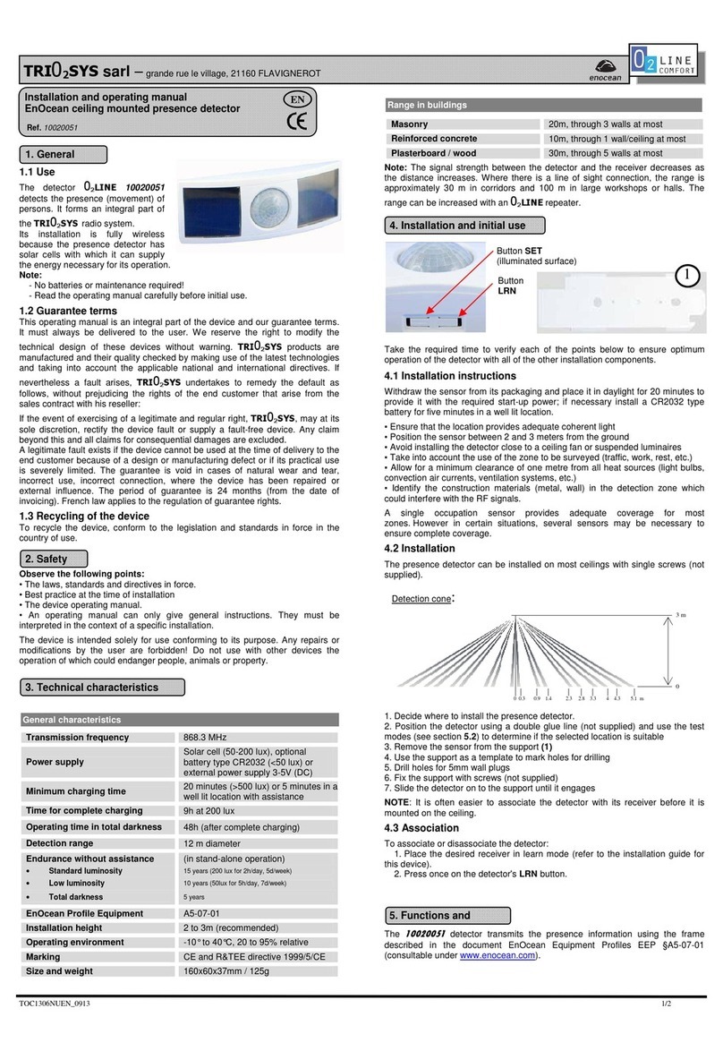
EnOcean O2LINE 10020051 User manual

EnOcean

EnOcean O2LINE 10020051 User manual

EnOcean EOSC User manual

EnOcean

EnOcean EOSC User manual

EnOcean EOSW User manual

EnOcean

EnOcean EOSW User manual

EnOcean Easyfit EMDC User manual

EnOcean

EnOcean Easyfit EMDC User manual

Popular Security Sensor manuals by other brands

GJD D-Tect Dual GJD360 manual

GJD

GJD D-Tect Dual GJD360 manual

Evikon PluraSens E2670-ETO user manual

Evikon

Evikon PluraSens E2670-ETO user manual

Johnson Controls MP-802 PG+ installation guide

Johnson Controls

Johnson Controls MP-802 PG+ installation guide

Honeywell DO800M quick start guide

Honeywell

Honeywell DO800M quick start guide

MGC MIX-4030 Installation and maintenance instructions

MGC

MGC MIX-4030 Installation and maintenance instructions

Radenso DS1 user manual

Radenso

Radenso DS1 user manual

Spectrex SharpEye 40/40 Series user guide

Spectrex

Spectrex SharpEye 40/40 Series user guide

Evikon PluraSens E2670-HFC user manual

Evikon

Evikon PluraSens E2670-HFC user manual

Kusam-meco 2800B Operation manual

Kusam-meco

Kusam-meco 2800B Operation manual

HomeMatic HMIP-SMO-A-2 Mounting instruction and operating manual

HomeMatic

HomeMatic HMIP-SMO-A-2 Mounting instruction and operating manual

ITALIANA SENSORI 8001-ISR001 Installation, operation and maintenance manual

ITALIANA SENSORI

ITALIANA SENSORI 8001-ISR001 Installation, operation and maintenance manual

Mini Gadgets CDHunter user manual

Mini Gadgets

Mini Gadgets CDHunter user manual

EpiSensor ZIO-20 user guide

EpiSensor

EpiSensor ZIO-20 user guide

Gira 180 plus installation instructions

Gira

Gira 180 plus installation instructions

HomeMatic HmIP-SMI Mounting instruction and operating manual

HomeMatic

HomeMatic HmIP-SMI Mounting instruction and operating manual

RS PRO RS-9680 instruction manual

RS PRO

RS PRO RS-9680 instruction manual

DeFelsko PosiTest High voltage Holiday Detector instruction manual

DeFelsko

DeFelsko PosiTest High voltage Holiday Detector instruction manual

Sinope WL4200C quick start guide

Sinope

Sinope WL4200C quick start guide

manuals.online logo
manuals.online logoBrands
  • About & Mission
  • Contact us
  • Privacy Policy
  • Terms and Conditions

Copyright 2025 Manuals.Online. All Rights Reserved.