Tinker & Rasor AP/W User manual

CORROSION MITIGATIONINSTRUMENTATION
P. O. B
OX
1667 S
AN
B
ERNARDINO
, C
A
92402
T
EL
: (909) 890-0700
F
AX
: (909) 890-0736
PRODUCT INSTRUCTIONS
Web: www.tinker-rasor.com
E-mail: Info@tinker-rasor.com
– 1 –
MODEL AP/W
(OLD AP to serial # 8043)
HOLIDAY DETECTOR
WARNING!!!!
THIS TYPE HOLIDAY DETECTOR GENERATES HIGH VOLTAGES FROM 800 TO 40,000 VOLTS. THE
OUTPUT VOLTAGES GENERATED ARE WITHIN THE SAFE LIMITS OF FATAL "SHOCK HAZARD"
ACCORDING TO THE U.S. GOVERNMENT STANDARDS. EXTREME CARE BY THE OPERATOR OF
THESE HOLIDAY DETECTORS MUST BE EXERCISED TO PREVENT ELECTRICAL SHOCK.
ELECTRICAL SHOCK FROM THIS EQUIPMENT CAN CAUSE SEVER DISCOMFORT AND MAY
CAUSE OPERATOR INJURY THROUGH FALLING OR OTHER MEANS.
ACCIDENTS DO NOT JUST HAPPEN; THEY ARE CAUSED!!!!
HOLIDAY DETECTOR FUNCTION
The Tinker & Rasor Models AP and AP/W Holiday Detectors are portable, all
purpose, inspection instruments. They are adaptable for use on both large and small
diameter pipe as well as flat surfaces when such surfaces are coated with a high
electrical resistant material and the surface beneath the coating is electrically
conductive. The Models AP and AP/W Holiday Detectors work equally well on damp
surfaces; they are especially desirable when humid conditions exist or when it has
recently rained.
UNPACKING & INSPECTION
Upon opening the carrying case, notice where the various components are located;
repack them in the same manner when not in use. Then remove all components
from the carrying case.
Inspection should be performed upon receipt. If damage has occurred in shipment,
file a claim with the carrier immediately. Check components (against packing slip) to
be sure nothing is missing.
If it is necessary to contact your supplier or Tinker & Rasor concerning damaged
or missing items, be sure to include all information such as serial number, purchase
order number and invoice number.
Safety Information for User
Unpacking and Reviewing your Tinker & Rasor Holiday Detector Before Every Use

CORROSION MITIGATIONINSTRUMENTATION
P. O. B
OX
1667 S
AN
B
ERNARDINO
, C
A
92402
T
EL
: (909) 890-0700
F
AX
: (909) 890-0736
PRODUCT INSTRUCTIONS
Web: www.tinker-rasor.com
E-mail: Info@tinker-rasor.com
– 2 –
•Make certain the inside of the case is clear and dry.
•Inspect each component for damage, such as cables, instrument & wand handles.
•Make sure all of the electrodes are clean.
•Verify the unit is fully charged.
•Verify that the output voltage is correctly set to the coating manufacturers recommend inspection voltage.
•If manufacturers requirements are not stated, NACE International, SSPC or ASTM Standards can be
followed.
AND……… ALWAYS READ THE INSTRUCTIONS THROGHLY PRIOR TO USING ANY TEST
EQUIPMENT!
WARNING! This is a HIGH VOLTAGE device capable of producing an electrical shock if not
properly grounded and/or operated in accordance with the instructions and procedures
prescribed in this manual!
DANGER! IF YOU HAVE A PACEMAKER DO NOT USE THIS DEVICE.
If you have a pacemaker, life critical electronic medical devices or any medical condition effected by High
Voltage, DO NOT use this type of equipment. Only trained and responsible personnel should operate high
voltage equipment. Alert all personnel nearby prior to testing and display warning signs. It is important to
realize you are now using a high voltage, low energy holiday detector. Tinker & Rasor holiday detectors,
APS & AP/W, are designed to generate between 800 to 35,000 volts, pulsating DC. While these voltages
are high, the energy emitted is well within US, OSHA guidelines. https://www.osap.org/page/GuideOSHA
Rubber or plastic gloves and non-conductive footwear can minimize potential shock. Keep in mind that the
shock prevention effectiveness of the rubber or plastic glove and footwear is limited to the condition of
their protective surface. Make sure your gloves and footwear are in good condition and have no holes or
tears. Most Portable Holiday Detectors are limited to finding defects in nonconductive coating materials.
Testing should ONLY be conducted clear of personnel not involved in the testing procedure. Personnel
operating Holiday Detectors should always be aware of their environment and the safety limitations
imposed by same. Operator should have an alert assistant, to ensure that all unauthorized personnel are
kept clear of the testing area.
DANGER!!! Portable Holiday Detectors create an arc or spark. Use of a Portable Holiday Detector in or
around combustible or flammable environments can result in an explosion. When operating in any
potentially hazardous area, consult with the plant or site safety officer before proceeding with a holiday
detection test in any potentially hazardous or suspect area.
CAUTION! DO NOT USE AROUND SENSITIVE ELECTRONICS OR RADIO EQUIPMENT. When “on”
but not in use, Tinker & Rasor Pulse Type Holiday Detectors, APW and APS will generate radio frequency
emissions which are within the limit defined by the Electromagnetic Compatibility Directive. Due to its
method of operation however, the APW and APS Pulse Type Holiday Detector will generate broadband RF
emissions when the unit is generating high voltage or when a spark is produced at the electrode. It is
therefore recommended that the user does not activate the high voltage within the vicinity of sensitive
electronics or radio equipment.
DO NOT SHORTEN THE GROUND CABLE. NEVER TOUCH THE BARE GROUND WIRE WHEN THE
DETECTOR IS TURNED ON.
WARNING! USE CAUTION WHEN RAINING. If it is raining then there is a safety concern for the operator.
Surface water on the sub straight is usually not conductive enough to transmit voltage, but almost any

CORROSION MITIGATIONINSTRUMENTATION
P. O. B
OX
1667 S
AN
B
ERNARDINO
, C
A
92402
T
EL
: (909) 890-0700
F
AX
: (909) 890-0736
PRODUCT INSTRUCTIONS
Web: www.tinker-rasor.com
E-mail: Info@tinker-rasor.com
– 3 –
contaminant will cause water to become more conductive. If water covers the wand handle while
connected to the APW Power-Pak or the APS Instrument, then the operator could become the return path
for the high voltage. While the output voltage will cause harm to a healthy person, according to OSHA, your
environment must be taken into consideration when operating this type of equipment. For example; if you
are standing on top of a flag pole and receive a jolt of high voltage, it will most likely cause you to jump,
and you will fall off the flag pole.
Stay Alert, Stay Aware and Stay Alive
.
If it isn’t raining, but the coating surface is wet, Tinker & Rasor Holiday Detectors are designed to minimize
the effects of damp or wet coatings. In extreme cases, “ghost” holidays might be witnessed, should a
continual path of water reach a holiday. If this continues, dry the sub straight and continue testing.
It is important to note that all accidents are preventable. Take caution when using Tinker &
Rasor holiday detectors or any other high voltage test equipment.
CHECK-OUT INSTRUCTIONS
Assure that Holiday Detector "ON/OFF" switch is in the "OFF" position.
Using the Battery Tester, insert test plug (on Battery Tester) into Holiday Detector
"charge plug" receptacle. Observe LED light, if "ON" battery has sufficient charge to
operate the detector. The battery tester is to be used only to test battery in case
holiday detector does not operate properly. It is not designed to test the true
condition nor the amount of charge left in the battery.
FOR MODEL AP HOLIDAY DETECTOR (ONLY)
A. Turn output voltage selection switch (on Detector) to desired voltage.
(Voltages are listed on the inside and outside of Detector back cover).
B. Insert leather belt into slide loops on back of Detector if belt mounted method
is to be used.
C. Uncoil high voltage cable and plug the long connector (3" collar) into one end
of adapter and screw wand handle onto other end of adapter; plug the short
connector (1-1/2" collar) into the Detector high voltage port.
D. Assemble the desired electrode to the wand assembly and apply to thepipe,
tank, or other structure to be inspected. An inspection electrode should
always make intimate contact with the surface to be inspected.
E. Turn "ON/OFF" switch to "ON" position. (Note: When the switch is "ON", a
buzzing should be heard coming from the Detector).
FOR MODEL AP/W HOLIDAY DETECTOR (ONLY)
A. Turn output voltage selection switch (on Detector) to desired voltage.

CORROSION MITIGATIONINSTRUMENTATION
P. O. B
OX
1667 S
AN
B
ERNARDINO
, C
A
92402
T
EL
: (909) 890-0700
F
AX
: (909) 890-0736
PRODUCT INSTRUCTIONS
Web: www.tinker-rasor.com
E-mail: Info@tinker-rasor.com
– 4 –
Voltages are listed on the individual PowerPak in ascending order, left to
right.
B. Insert leather belt into slide loops on back of Detector if belt mounted method
is used.
C. Uncoil ground wire and plug connector end into Detector port marked
"ground". (The ground wire will trail on bare earth).
D. Attach wand to threaded, male end of PowerPak. Insert PowerPak cable
(male connector) into female connector of PowerPak. Insert other end of
PowerPak cable into “HighVoltage" port on Detector.
Note: Never turn the AP/W on without plugging in the "HIGH VOLTAGE" cable or
unplug the cable while the unit is in the on position! Doing so will damage internal
components.
E. Assemble the desired electrode to the wand assembly and apply to the pipe,
tank, or other structure to be inspected. An inspection electrode should
always make intimate contact with the surface to be inspected.
F. Turn "ON/OFF" switch to the "ON" position. (Note: When the switch is "ON", a
buzzing sound may be heard coming from the Detector).
G. The AP/W is now ready to operate.
OPERATING CONDITIONS
The structure to be inspected should be clean and free of any debris.
The surface should be dry. Some moisture or heavy humidity should not effect
the inspection.
The electrode used for the inspection should be suitable for the type of structure
and the type of coating on the structure.
The exploring electrode must maintain intimate contact with the coating at all
times. Coatings with significant “peaks and valleys”, where the max. height and
min. height of the coating is greater than 10 mils, may require a wire brush
electrode, opposed to a coiled spring or flat conductive rubber electrode.
Do not use the holiday detector if the operator may be in contact with standing
water on a surface of the structure (tanks, internal pipes, etc.)
It is not required that the operator wear any special equipment or clothing. It is
recommended that the operator wear clothing suitable for field work, such as

CORROSION MITIGATIONINSTRUMENTATION
P. O. B
OX
1667 S
AN
B
ERNARDINO
, C
A
92402
T
EL
: (909) 890-0700
F
AX
: (909) 890-0736
PRODUCT INSTRUCTIONS
Web: www.tinker-rasor.com
E-mail: Info@tinker-rasor.com
– 5 –
jeans or work pants, work shirt and work boots with non-conductive soles.
OPERATING METHODS
A. Grounding
1. A good ground system will always give the best and most reliable
inspection.
The structure to be inspected must itself be grounded to earth at some
point.
2. If individual joints of pipe are to be inspected which are notelectrically
connected, each joint must be grounded.
B. Inspection Speed
Speed of the electrode travel over the inspection surface should
be moderate. Moving the electrode at an excessive speed can result in a
faulty inspection.
C. Operating Checks
1. Occasional checks of the Detector can be made if no holidays are being
found. Move the inspection electrode to the coating's edge (where the
bare conductive surface is); note that spark and signal should both
occur.
2. If the signal does not sound when the spark jumps, the "ground return"
resistance is exceptionally high. (Example: very dry soil or very large
diameter pipe). To improve the "ground", make a direct connection
between the structure under inspection and the Detector's ground wire.
Remember, the structure itself must have a connection to earth ground,
too.
ABOUT YOUR HOLIDAY DETECTOR
A. Sensitivity Switch
The sensitivity of the Holiday Detector may be adjusted by turning the 4-
position switch; access the switch with a screwdriver through the porthole
located on the back panel in the belt recess. (See paragraph 6C).
B. Output Voltages

CORROSION MITIGATIONINSTRUMENTATION
P. O. B
OX
1667 S
AN
B
ERNARDINO
, C
A
92402
T
EL
: (909) 890-0700
F
AX
: (909) 890-0736
PRODUCT INSTRUCTIONS
Web: www.tinker-rasor.com
E-mail: Info@tinker-rasor.com
– 6 –
Output voltages are measured direct-connected, "open-circuit" using Tinker
& Rasor Model "PRM" Peak Reading Voltmeter (calibrated).
CAUTION: Before disassembly of components, turn the "ON/OFF" switch to "OFF"
position.
INSTRUMENT SERVICING
A. Cleaning
Keep instrument clean and dry. Clean instrument case with soft cloth
dampened with kerosene, then wipe dry. Do not use solvents: (lacquer
thinner, Methyl-Ethyl-Ketone, etc.)
B. Voltage Output Checks
1. Low output voltage:
a. Check position of voltage selector switch.
b. Check battery condition using Battery Tester. (See later
comments on Battery).
c. Check for "parted" conductor in wand and ground wire(s).
2. No Output Voltage:
a. Check battery condition using Battery Tester. (See later
comments on Battery).
b. Check fuse located on printed circuit board inside instrument. If
fuse is blown, look for shorted wire in primary circuit. Replace
fuse with 2.0 amp fuse, type 3AG.
c. Check battery leads and the power switch for open circuit. Proper
input current is .7 to .9 amperes.
C. False Signal Indication Check
1. Adjust 4-position rotary signal sensitivity switch through portholeprovided
on back panel in the belt recess.
a. Electrical "load" conditions vary greatly through pipe sizes, coating

CORROSION MITIGATIONINSTRUMENTATION
P. O. B
OX
1667 S
AN
B
ERNARDINO
, C
A
92402
T
EL
: (909) 890-0700
F
AX
: (909) 890-0736
PRODUCT INSTRUCTIONS
Web: www.tinker-rasor.com
E-mail: Info@tinker-rasor.com
– 7 –
thickness and climatic conditions. The counter-clockwise position is
the most "signal sensitive".
b. Coated concrete pipes would use this position. In other cases, it is
best to start out using position
2. or the next position in
a. clockwise direction.
b. check for "parted" conductor in wand and ground wire.
D. No signal with Spark Discharge
1. Check position of signal sensitivity switch.
2. Read item 3 --C under "Instrument Servicing".
3. Refer to paragraph on "Operating Checks".
BATTERY CHARGING - CAUTION
Place Holiday Detector "ON/OFF" Switch in "OFF" position while charging battery.
A. Use only the Battery Charger provided (Part #031-005).
B. Recharge battery in the instrument. Ventilation holes in front and back of
instrument case should be kept open.
C. Plug charger into polarized receptacle of instrument.
Note: Battery cannot be tested or charged if instrument power switch is in the
"ON" position.
D. Plug A.C. power cord into any 120 volt 60 Hz outlet..
E. Charge battery for no more than 14 hours. 14 Hours is recommended only on
completely discharged or new replacement batteries.
F. Charge battery at temperatures above 45 degrees for best results.
G. If charger pilot light "out": (indicates Charger is not operating).
1. Check position of power switch.

CORROSION MITIGATIONINSTRUMENTATION
P. O. B
OX
1667 S
AN
B
ERNARDINO
, C
A
92402
T
EL
: (909) 890-0700
F
AX
: (909) 890-0736
PRODUCT INSTRUCTIONS
Web: www.tinker-rasor.com
E-mail: Info@tinker-rasor.com
– 8 –
2. Check for "shorted" battery cell(s).
H. Disconnect charger from battery and A.C. outlet when not in use.
BATTERY MAINTENANCE
A. When instrument fails to operate in normal manner, battery maybe fully
discharged.
Recharging before this happens can extend the useful life of the battery
considerably.
B. Store at normal room temperature when not in use.
C. If battery has not been used for six month or more, discharge completely and
recharge for 14 hours minimum.
Note: If Holiday Detector fails to operate in normal manor, the first step is to test the
battery condition.
SHIPPING INSTRUCTIONS
All instruments being returned for repair should be sent PREPAID to Tinker & Rasor
address below:
Tinker & Rasor
791 S. Waterman Ave
San Bernardino, CA 92408
Include with shipment: Information on the nature of the problem, purchase order, serial number and return
delivery address.
Immediate service is guaranteed!
103-079

CORROSION MITIGATIONINSTRUMENTATION
P. O. B
OX
1667 S
AN
B
ERNARDINO
, C
A
92402
T
EL
: (909) 890-0700
F
AX
: (909) 890-0736
PRODUCT INSTRUCTIONS
Web: www.tinker-rasor.com
E-mail: Info@tinker-rasor.com
– 9 –
.9 – 3.4 K.V.
L = .9 (900v), 2 = 1.4 (1,400v), 3 = 2. (2,000v), 4 = 2.5 (2,500v), 5 = 3. (3,000v), H = 3.4 (3,400v)
MODEL AP/W
HOLIDAY DETECTOR
POWERPAK SETTINGS
The Model AP/W, pictured at right, is a high voltage holiday detector.
It can provide output voltages from 900volts to 35,000 volts, DC. The
Model AP/W is a pulse –type holiday detector, meaning that the
output voltage comes in pulses instead of continuous current. Pulse –
type holiday detectors are safer to use, do not track through moisture
to nearby holidays, and do not damage coatings as a continuous
output instrument may.
The Model AP/W uses a PowerPak to determine the output voltage of
the instrument. There are four (4) PowerPaks to choose from, each
with a range of six (6) voltage settings.
Because the output voltage is determined by which PowerPak is
being used, the Model AP/W does not have a voltage guide on the
instrument itself. The instrument has a voltage selector in the upper
right corner of its face, which shows the following settings:
L – (Low), 2, 3, 4, 5, H – (High)
Each of these settings corresponds directly to the range engraved on
the PowerPak being used. As shown in the picture to the right, each
PowerPak is engraved with its range of output voltages. The output
voltages are engraved in Kilovolts. This means that 900 volts is
shown as .9, and 3,400 volts is shown as 3.4 K-V.
For the PowerPak shown at right, the settings on the Model AP/W
would correspond to the PowerPak output in this way:
The other PowerPaks available are:
3.5 – 10 K.V.
L = 3.5 (3,500v), 2 = 5. (5,000v), 3 = 6. (6,000v), 4 = 7.5 (7,500v), 5 = 8.5 (8,500v), H = 10. (10,000v)
6 – 16 K.V.
L = 6. (6,000v), 2 = 8. (8,000v), 3 = 10. (10,000v), 4 =1 2.5 (12,500v), 5 = 15. (15,000v), H = 16. (16,000v)
12.5 – 35 K.V.
L = 12.5 (12,500v), 2 = 17.5 (17,500v), 3 = 20. (20,000v), 4 = 27. (27,000v), 5 = 31. (31,000v), H = 35. (35,000v)
Other manuals for AP/W
1
Table of contents
Other Tinker & Rasor Security Sensor manuals

Tinker & Rasor
Tinker & Rasor PD Instruction sheet
Tinker & Rasor
Tinker & Rasor M/2 Instruction sheet

Tinker & Rasor
Tinker & Rasor 7-T Instruction sheet
Tinker & Rasor
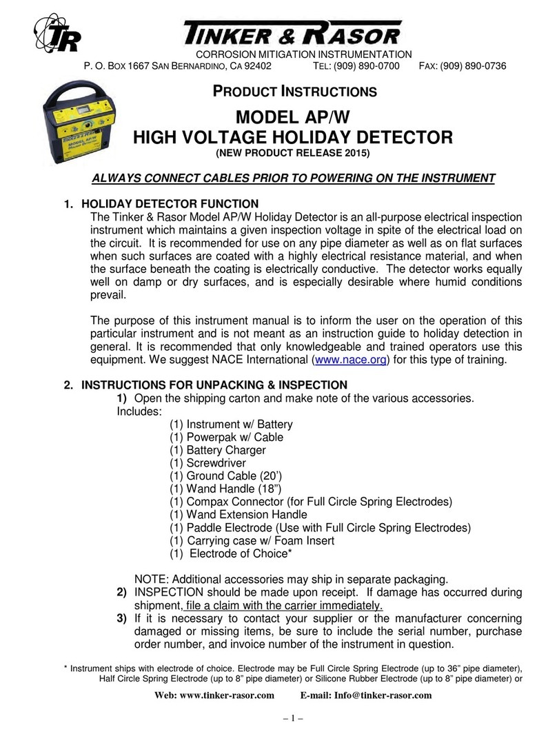
Tinker & Rasor AP/W User manual
Tinker & Rasor
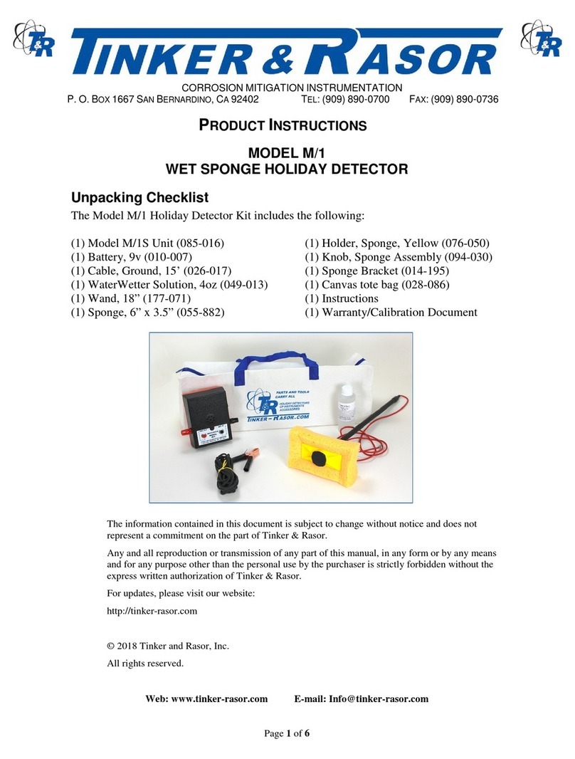
Tinker & Rasor M/1 Instruction sheet
Tinker & Rasor
Tinker & Rasor AP/AC Instruction sheet
Tinker & Rasor
Tinker & Rasor AP User manual
Tinker & Rasor
Tinker & Rasor APS Instruction sheet
Tinker & Rasor
Tinker & Rasor M1/AC Instruction sheet
Tinker & Rasor
Tinker & Rasor APS User manual
