Yaesu FT-25R User manual

2FT-25R/FT-25E Advance Manual
Contents
About this manual ........................................................4
RF Squelch....................................................................5
Checking the Battery Voltage......................................6
VOX Operation (with earpiece mic or Internal /
External mic).................................................................7
VFO Split Mode.............................................................8
Using the Squelch Feature ..........................................9
Selecting the Squelch Type..........................................9
Setting CTCSS Tone frequency .................................10
Setting DCS CODE number....................................... 11
CTCSS/DCS/PAGER/ARTS Bell Operation.............. 11
EPCS (Enhanced Paging & Code Squelch)...............12
Storing the CTCSS Tone Pairs for EPCS Operation 12
Activating the Enhanced Paging & Code Squelch
System .....................................................................13
Paging Answer Back ................................................14
Memory Bank Operation............................................15
Assigning Memories to a Memory Bank...................15
Memory Bank Recall ................................................15
Removing a Memory channel from a Memory Bank 16
Returning To Memory mode from Memory Bank
operation ..................................................................16
Memory Only Mode ....................................................17
Scanning .....................................................................18
Memory scanning.......................................................18
How to Skip (Omit) a Channel during Memory Scan
Operation .................................................................18
Weather Alert Scan ....................................................19
Programmable (Band Limit) Memory Scan (PMS).....20
“Priority Channel” Scanning .......................................21
VFO Priority..............................................................21
Memory Channel Priority..........................................21

3FT-25R/FT-25E Advance Manual
HOME Channel Priority............................................22
Priority Revert Mode ................................................22
WX Channel Priority.................................................22
Automatic Lamp Illumination on Scan Stop................23
Emergency Channel Operation.................................24
ARTS (Automatic Range Transponder System) ......25
Basic ARTS Setup and Operation..............................25
ARTS Alert Beep Options.........................................26
ARTS Polling Time Options......................................26
CW Identifier Setup..................................................27
DTMF Operation..........................................................28
DTMF Autodialer ......................................................28
Manual DTMF Tone Generation...............................28
Sending the DTMF code by Autodialer ....................29
Miscellaneous Settings..............................................30
Password....................................................................30
Setting Password and Turning the Password Feature
ON or OFF ...............................................................30
Changing the Channel Steps .....................................30
TX Battery Saver........................................................31
Disabling the TX/BUSY LED Indicator .......................31
Automatic Power-Off (APO) Feature..........................32
Transmitter Time-Out Timer (TOT).............................32
Busy Channel Lock-Out (BCLO) ................................33
Changing the TX deviation Level ...............................33
Voice Compander Feature .........................................34
Inversion Scramble (Asian version only)....................34
Cloning ........................................................................35
Set (Menu) Mode.........................................................36

FT-25R/FT-25E Advance Manual 4
About this manual
This manual provides information to assist in using the many FT-25R/E useful
and convenient features.
Refer to this Advance Manual along with the Operating Manual.
This manual contains symbols and conventions to call attention to important in-
formation.
Symbols Description
This icon indicates cautions and alerts the user should be aware of.
This icon indicates helpful notes, tips and information.
This icon indicates other pages containing relevant information.
• The settings of the transceiver at the time of purchase are referred to as the “default”
or “default setting”.
• The names of Set Mode items that are displayed on the LCD, and the transceiver
key names, are presented in bold characters in this manual.

FT-25R/FT-25E Advance Manual 5
RF Squelch
A special RF Squelch feature may be set so that only signals exceeding a certain S-meter
level will open the squelch.
1. Press and hold the Fkey to enter the Set Mode.
2. Press the [▲] or [▼] key to select Set Mode Item
“26 RF SQL”.
3. Press the Fkey to enable adjustment of this item.
4. Press the [▲] or [▼] key to select the desired signal strength level for the squelch
threshold (S-1, S-2, S-3, S-4, S-5, S-6, S-8, S-FULL, or OFF).
5. Press the PTT switch to save the new setting and return to normal operation.

FT-25R/FT-25E Advance Manual 6
Checking the Battery Voltage
The FT-25R/E microprocessor includes programming which will measure the current
battery voltage.
1. Press and hold the Fkey to enter the Set Mode.
2. Press the [▲] or [▼] key to select Set Mode Item
“10 DC VOLT”.
3. Press the Fkey to display the current DC Voltage.
4. Press the PTT switch to return to normal operation.
Also on turning the transceiver ON, the current battery voltage appears
briey.

FT-25R/FT-25E Advance Manual 7
VOX Operation (with earpiece mic or Internal / External mic)
The VOX system provides automatic transmit/receive switching based on voice input to a
VOX compatible headset or internal/external microphone. With the VOX system enabled,
you do not need to press the PTT switch in order to transmit.
1. Press and hold the Fkey to enter the Set Mode.
2. Press the [▲] or [▼] key to select Set Mode Item
“35 VOX”.
3. Press the Fkey to enable adjustment of this item.
4. Press the [▲] or [▼] key to select “VOX ON” or “VOX OFF (default setting)”.
5. Press the PTT switch to save the new setting and return to normal operation.
When the VOX system is activated, the “ ” icon will appear on the display.

FT-25R/FT-25E Advance Manual 8
VFO Split Mode
When working on repeaters with odd splits, or communicating with astronauts on orbiting
space vehicles, it may be necessary to use nonstandard splits between the receive and
transmit frequencies. If the application is infrequent enough not to warrant the dedication
of a memory channel for this purpose, the “VFO Split” mode may be used. Here is the
procedure for going Split:
1. Press and hold the Fkey to enter the Set Mode.
2. Press the [▲] or [▼] key to select Set Mode Item “34 VFO.SPL”.
3. Press the Fkey to enable adjustment of this Item.
4. Press the [▲] or [▼] key to select “VSP.ON”.
5. Press the PTT switch to save the new setting and
return to normal operation.
6. Press the [#VFO] key twice, as needed, to select VFO-A.
7. Set VFO-A for the desired receiving (downlink) frequency (e.g.145.800 MHz).
8. Press the [#VFO] key to set VFO-B for desired transmit (uplink) frequency (e.g.
144.475 MHz).
9. Press the [#VFO] key to re-establish VFO-A as the “Main” (receive) VFO.
The transceiver will now be operating in the Split mode.
10. When the PTT switch is pressed to transmit, VFO-A and VFO-B will reverse positions.
To modify the VFO-B (transmit) frequency (for Doppler Shift correction, etc.), just
press the [#VFO] key, make the necessary change, and then press the [#VFO] key
once more to restore VFO-A to the “receive VFO” position.

FT-25R/FT-25E Advance Manual 9
Using the Squelch Feature
Many repeater systems require a very-low-frequency audio tone be superimposed on
the FM carrier in order to activate the repeater. This helps prevent false activation of the
repeater by radar or spurious signals from other transmitters. This tone system, called
“CTCSS” (Continuous Tone Coded Squelch System), is included in the FT-25R/E. The
CTCSS is very easy to activate.
Selecting the Squelch Type
1. Press and hold the Fkey to enter the Set Mode.
2. Press the [▲] or [▼] key to select Set Mode Item “29 SQL TYPE”.
3. Press the Fkey to enable adjustment of this Item.
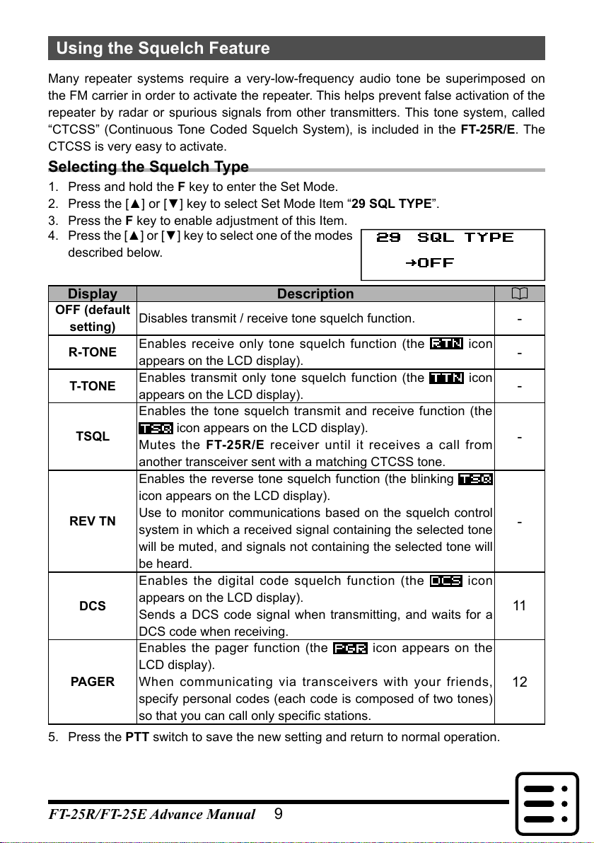
4. Press the [▲] or [▼] key to select one of the modes
described below.
Display Description
OFF (default
setting) Disables transmit / receive tone squelch function. -
R-TONE Enables receive only tone squelch function (the icon
appears on the LCD display). -
T-TONE Enables transmit only tone squelch function (the icon
appears on the LCD display). -
TSQL
Enables the tone squelch transmit and receive function (the
icon appears on the LCD display).
Mutes the FT-25R/E receiver until it receives a call from
another transceiver sent with a matching CTCSS tone.
-
REV TN
Enables the reverse tone squelch function (the blinking
icon appears on the LCD display).
Use to monitor communications based on the squelch control
system in which a received signal containing the selected tone
will be muted, and signals not containing the selected tone will
be heard.
-
DCS
Enables the digital code squelch function (the icon
appears on the LCD display).
Sends a DCS code signal when transmitting, and waits for a
DCS code when receiving.
11
PAGER
Enables the pager function (the
v
icon appears on the
LCD display).
When communicating via transceivers with your friends,
specify personal codes (each code is composed of two tones)
so that you can call only specic stations.
12
5. Press the PTT switch to save the new setting and return to normal operation.

10
Using the Squelch Feature
FT-25R/FT-25E Advance Manual
Setting CTCSS Tone frequency
The tone frequency can be selected from 50 frequencies (67.0 Hz to 254.1 Hz).
1. Press and hold the Fkey to enter the Set Mode.
2. Press the [▲] or [▼] key to select Set Mode Item “8 CTCSS”
3. Press the Fkey to enable adjustment of this item.
4. Press the [▲] or [▼] key to select the “TX” or “RX”, then press the Fkey.
Display Description
TX To set the tone frequency on transmitting.
RX To set the tone frequency on receiving.
5. Press the [▲] or [▼] key until the needed Tone Frequency is displayed. (Obtain the
correct tone from the repeater owner/operator if you don’t know it).
CTCSS TONE FREQUENCY (Hz)
67.0 69.3 71.9 74.4 77.0 79.7
82.5 85.4 88.5 91.5 94.8 97.4
100.0 103.5 107.2 110.9 114.8 118.8
123.0 127.3 131.8 136.5 141.3 146.2
151.4 156.7 159.8 162.2 165.5 167.9
171.3 173.8 177.3 179.9 183.5 186.2
189.9 192.8 196.6 199.5 203.5 206.5
210.7 218.1 225.7 229.1 233.6 241.8
250.3 254.1 – – – –
6. When you have made your selection, press the F key to save the desired tone fre-
quency.
7. Press and hold the Fkey to move the upper menu contents in the Set Mode.
8. Press the PTT switch to exit to normal operation.

11
Using the Squelch Feature
FT-25R/FT-25E Advance Manual
Setting DCS CODE number
The DCS code can be selected from 104 types (023 to 754).
1. Press and hold the Fkey to enter the Set Mode.
2. Press the [▲] or [▼] key to select Set Mode Item “11 DCS CODE”
3. Press the Fkey to enable adjustment of this item.
4. Press the [▲] or [▼] key to select “TX” or “RX”,
then press the Fkey.
5. Press the [▲] or [▼] key to select the desired DCS Code (a three digit number).
Ask the repeater owner/operator if you don’t know the DCS Code; if you are working
simplex, just set up the DCS Code to be the same as that used by your friend(s).
DCS CODE
023 025 026 031 032 036 043 047 051 053
054 065 071 072 073 074 114 115 116 122
125 131 132 134 143 145 152 155 156 162
165 172 174 205 212 223 225 226 243 244
245 246 251 252 255 261 263 265 266 271
274 306 311 315 325 331 332 343 346 351
356 364 365 371 411 412 413 423 431 432
445 446 452 454 455 462 464 465 466 503
506 516 523 526 532 546 565 606 612 624
627 631 632 654 662 664 703 712 723 731
732 734 743 754 – – – – – –
6. When you have made your settings, press the F key to save the desired DCS Code.
7. Press and hold the Fkey to move the upper menu contents in the Set Mode.
8. Press the PTT switch to exit to normal operation.
CTCSS/DCS/PAGER/ARTS Bell Operation
During CTCSS Decode, DCS, PAGER, ARTS operation, you may set up the Transceiver
such that a ringing “bell” sound alerts you to the fact that a call is coming in.
1. Press and hold the Fkey to enter the Set Mode.
2. Press the [▲] or [▼] key to select Set Mode Item “6 BELL”
3. Press the Fkey to enable adjustment of this item.
4. Press the [▲] or [▼]key to set the desired number
of Bell rings.
The available choices are “1Time”, “3Times”,
“5Times”, “8Times”, “CONTINUE” (continuous
ringing), or “OFF (default setting)”.
5. Press the PTT switch to save the new setting and return to normal operation.

12
Using the Squelch Feature
FT-25R/FT-25E Advance Manual
EPCS (Enhanced Paging & Code Squelch)
The FT-25R/E includes an Enhanced CTCSS tone encoder/decoder and a dedicated
microprocessor providing paging and selective calling features. The squelch permits
directing calls to specific stations (Paging), and receiving only the calls directed to stations
programmed with a similar code (Code Squelch).
The paging and code squelch systems use two pairs of (alternately switched) CTCSS
tones which are stored in the pager memories. Basically, the receiver remains silent until
it receives the CTCSS tone pair that matches those stored in the Receiver Pager Memory.
The squelch then opens so the caller is heard, and the paging ringer (if activated)
immediately sounds. When the PTT switch is pressed to transmit, the CTCSS tone pair
which is stored in the Transmitting Pager Memory will be transmitted automatically.
On the paged transceiver, the squelch will close automatically after the incoming page
ends. Meanwhile, on the paging transceiver, the Enhanced Paging and Code Squelch
system will be disabled after the PTT switch is released, after the paging transmission.
The Enhanced Paging and Code Squelch system may be re-activated again using Set
Mode Item “21 PAGER”, if desired.
Storing the CTCSS Tone Pairs for EPCS Operation
1. Press and hold the Fkey to enter the Set Mode.
2. Press the [▲] or [▼] key to select Set Mode Item “21 PAGER”
3. Press the Fkey to enable adjustment of this item.
4. Press the Fkey.
The rst TX tone number will blink.
5. Press the numeric keys to input the CTCSS Tone number which corresponds to the
first tone of the CTCSS Tone Pair.
The tone numbers are listed below.
CTCSS TONE NUMBER
No. Hz No. Hz No. Hz No. Hz No. Hz
01 67.0 11 94.8 21 131.8 31 171.3 41 203.5
02 69.3 12 97.4 22 136.5 32 173.8 42 206.5
03 71.9 13 100.0 23 141.3 33 177.3 43 210.7
04 74.4 14 103.5 24 146.2 34 179.9 44 218.1
05 77.0 15 107.2 25 151.4 35 183.5 45 225.7
06 79.7 16 110.9 26 156.7 36 186.2 46 229.1
07 82.5 17 114.8 27 159.8 37 189.9 47 233.6
08 85.4 18 118.8 28 162.2 38 192.8 48 241.8
09 88.5 19 123.0 29 165.5 39 196.6 49 250.3
10 91.5 20 127.3 30 167.9 40 199.5 50 254.1
6. Press the Fkey to input the second TX tone.
The second TX tone number will blink.

13
Using the Squelch Feature
FT-25R/FT-25E Advance Manual
7. Press the numeric keys to input the CTCSS Tone number which corresponds to the
second tone of the CTCSS Tone Pair.
8. Press the Fkey to complete TX tone number.
9. Press the [▲] or [▼] key select “RX”, then press the Fkey.
To set the RX tone number, repeat the above procedure.
10. Press the PTT switch to save the new setting and return to normal operation.
• The default Tone number: [05 47].
• Even if the rst and second parts of your personal code are reversed, i.e.,
[47 05] from [05 47] they are still recognized as the same code.
Activating the Enhanced Paging & Code Squelch System
1. To activate the EPCS function, see page 9 “Se-
lecting the Squelch Type”.
The
v
icon will appear on the LCD display.
v
While the EPCS function is activated, the CTCSS and DCS settings are
disabled.
2. Press the PTT switch to activate the EPCS function.
3. To disable the EPCS function, just repeat the above procedure, Press the [▲] or [▼]
key to select “OFF” in step 1 above.
During EPCS operation, the FT-25R/E may be set up to sound a ringing
“bell” alert when an EPCS call is coming in, as described previously.See
page 11 for details.
Being Called by the Remote Station
(Standby Operation)
If the “bell” alert is turned on, when an
EPCS call is received from a remote
station the “PAGING” announcement
will be shown on the LCD display and
the bell will sound.
v

14
Using the Squelch Feature
FT-25R/FT-25E Advance Manual
Paging Answer Back
When the PTT switch is pressed in response to answer a paging call, the FT-25R/E
transmits the same CTCSS tone pair. This tone pair will open the Code Squelch of the
calling station. If preferred, the FT-25R/E may be setup to respond to the pager calls
automatically (“transpond”).
1. Press and hold the Fkey to enter the Set Mode.
2. Press the [▲] or [▼] key to select Set Mode Item “21 PAGER”
3. Press the Fkey to enable adjustment of this item.
4. Press the [▲] or [▼] key select the “ACK”, then
press the Fkey.
5. Press the [▲] or [▼] key to select “ON”, then press
the Fkey.
6. Press the PTT switch to save the new setting and return to normal operation.
• Even if the “ACK” is “ON”, also change the Set Mode Item “SQL
TYPE” to “PAGER”, to activate the Paging Answer Back feature.
• The Paging Answer Back feature constitutes a form of “remote control”
operation that may be restricted to certain frequencies. U.S. users
should conrm the current status of §97.201(b) of the FCC’s rules
governing the Amateur service before utilizing this feature on the 144
MHz band.

FT-25R/FT-25E Advance Manual 15
Memory Bank Operation
The large number of memories available in the FT-25R/E could be difficult to manage
without some means of organizing them. Fortunately, the FT-25R/E includes a provision
to divide the memories into as many as ten Memory Groups. The memories can be
categorized in a manner convenient for the operator.
Assigning Memories to a Memory Bank
• Each memory channel may be
assigned into several Memory
Banks.
• The PMS memory channels
(L1/U1 through L10/U10) may
not be assigned to a Memory
Bank.
Memory Channel
CH 001 144.000 MHz
CH 002 145.500 MHz
CH 003 145.500 MHz
CH 004 145.215 MHz
CH 005 145.800 MHz
CH 006 146.000 MHz
CH 007 108.000 MHz
CH 198 145.620 MHz
CH 199 89.000 MHz
CH 200 87.500 MHz
Memory Bank “2”
Club Channels
Memory Bank “1”
144 MHz Amateur Band Channels
Memory Bank “3”
FM Broadcast BandChannels
1. Recall the memory channel to be assigned to a Memory Bank.
2. Press and hold the [#VFO] key, then press the [▲] or [▼] key to select the Memory
Bank number (“BANK 1” to “BANK10”) as the Memory Bank to assign for this
channel.
About icons on the Memory Bank
• Bank Number blinking: Assignable
• Bank Number not blinking: Assigned
• “SEL” icon blinking: Selecting ON
v
v
v v
Bank Number“SEL” Icon
3. Press and hold the Fkey to copy the memory channel data into the Memory Bank.
The blinking Bank Number stops blinking.
4. Press the PTT switch to return to the memory channel.
Memory Bank Recall
1. Press the [ MR] key, if needed, to enter the Memory mode.
2. Press and hold the [#VFO] key, then press the [▲] or [▼] key to select the desired
Memory Bank (“BANK 1” through “BANK10”).
3. Press the [ MR] key momentarily; now, press the [▲] or [▼] key to select the memory
channel.
• Only memory channels assigned in the current memory Bank will be available.
• The “
v
” indication will appear at the left side
of the frequency display while operating within a
Memory Bank.
• The memory channel number appears above
the"
v
" icon.
v
• To change to another Memory Bank, press and hold the [#VFO] key.

16
Memory Bank Operation
FT-25R/FT-25E Advance Manual
Returning To Memory mode from Memory Bank operation
1. While in the Memory Bank Mode, press and hold
the [#VFO] key, and then press the [▲] or [▼] key
to select “NO BANK”.
2. Press the [ MR] key to return to Memory Mode.
v
v
v v
v
Removing a Memory channel from a Memory Bank
1. Recall the Memory Bank that contains the memory channel to delete.
2. Press the [▲] or [▼] key to select the Memory channel to delete, then press and hold
the [#VFO] key.
The Memory channel to be deleted from the
Memory Bank will appear on the LCD.
v
v
v v
v
3. Press and hold the Fkey to remove the memory channel.
• If assigned memory channels still remain in the Memory Bank, the display will return
to a Memory Bank channel.
• If there is no assigned memory channel in the Memory Bank, the display will return
to the Memory channel.

FT-25R/FT-25E Advance Manual 17
Memory Only Mode
Once memory channel programming has been completed, the transceiver may be placed
in a “Memory Only” mode, whereby VFO operation is impossible.
1. Turn the transceiver OFF.
2. Press and hold the MONI/T.CALL key and the PTT switch simultaneously, while turn-
ing the transceiver ON.
When the LCD backlight is on, release the MONI/T.CALL key and the PTT switch.
3. Press the [▲] or [▼] key to select “F5:MEM-ONLY”.
4. Press the Fkey momentarily to complete the procedure.
To return to normal operation, repeat the above power-on procedure.

FT-25R/FT-25E Advance Manual 18
Scanning
Memory scanning
Memory scanning is likewise easy to initiate:
1. Select the Memory mode by pressing the [ MR] key, if necessary.
2. Press and hold either the [▲] or [▼] key to initiate upward or downward scanning,
respectively.
3. When the scanner encounters a signal strong enough to open the squelch, scanning
will halt temporarily; the decimal point of the frequency display will blink during this
“Resuming” condition.
4. Scanning will then resume according to the Scan-Resume mode selected in Set Mode
“25 RESUME” (Ssee page 37).
5. To cancel scanning, press the PTT switch, Fkey, [#VFO] key, [▲] key, [▼] key or the
[MR] key.
How to Skip (Omit) a Channel during Memory Scan Operation
Some continuous-carrier stations like a Weather Broadcast station will seriously impede
scanner operation when using the “Carrier Drop” Scan Resume mode, as the incoming
signal will not pause long enough for the transceiver to resume scanning. Such channels
may be “Skipped” during scanning, if desired:
1. Press and hold the Fkey to enter the Set mode.
2. Press the [▲] or [▼] key to select Set Mode Item “28 SKIP”.
3. Press the Fkey to enable adjustment of this Set Mode Item.
4. Press the [▲] or [▼] key to select a channel to skip,
and then press the Fkey.
The selected Memory Channel will be inversely
displayed by black.
5. Press the PTT switch to return to normal operation.
When the “skipped” memory channel
is manually recalled, the “ ”
icon will appear below the memory
channel number, indicating it is to be
ignored during scanning.

19
Scanning
FT-25R/FT-25E Advance Manual
Weather Alert Scan
This feature allows monitoring the Weather
Broadcast Memory Channels for the presence
of the NOAA Alert Tone while operating in VFO
scan, or Memory channel scan.
CH Frequency CH Frequency
01 162.550 MHz 06 162.500 MHz
02 162.400 MHz 07 162.525 MHz
03 162.475 MHz 08 161.650 MHz
04 162.425 MHz 09 161.775 MHz
05 162.450 MHz 10 163.275 MHz
When the Weather Alert Scan feature is engaged in the VFO mode, or the Memory mode,
the FT-25R/E will check the Weather Broadcast Memory Channels for the NOAA Alert
Tone every five seconds while scanning. the display will be observed periodically shifting
from the scanner to the Weather Broadcast bank, and scanning the Weather channels
quickly in search of the Alert Tone, after which regular scanning will resume for another
five seconds.
To scan only the Weather Broadcast channels, press and hold the [1] key, and then press
the PTT switch (or press and hold the [▲] or [▼] key).
1. Press and hold the Fkey to enter the Set Mode.
2. Press the [▲] or [▼] key to select Set Mode Item “38 WX ALERT”.
3. Press the Fkey momentarily to enable adjustment of this item.
4. Press the [▲] or [▼] key to select “ALT . ON” or
“ALT . OFF (default setting)”.
5. Press the PTT switch to save the new setting and return to normal operation.
• When scanning the Weather Broadcast Channels, the transceiver will
remain muted until the Alert Tone is received. This yields a long period
of monitoring time, as no power will be consumed for audio output while
scanning for the Alert Tone is in progress.
• When the scanner encounters an Alert Tone, the scanning will stop. The
“ALARM” message will appear on the display and the transceiver will
sound a beep.

20
Scanning
FT-25R/FT-25E Advance Manual
Programmable (Band Limit) Memory Scan (PMS)
This feature allows setting sub-band limits for either scanning or manual VFO operation.
For example, you might wish to set up a limit (in North America) of 144.300 MHz to
148.000 MHz to prevent encroachment into the SSB/CW “Weak Signal” portion of the
band below 144.300 MHz. Here’s how to do this:
1. Set the transceiver to the VFO mode, if necessary.
2. Set 144.300 MHz into Memory Channel L01 (the “L” designates the Lower sub-band
limit).
3. Likewise, set 148.000 MHz into Memory Channel U01 (the “U” designates the Upper
sub-band limit).
4. Press and hold the [#VFO] key.
5. Press the [▲] or [▼] key to select the “PMS-1”
PMS-(number) will change depending on the currently-selected PMS
frequency pair.
6. Press the PTT switch to return to normal operation.
For more details on programmed mode (VFO) scan, refer to the FT-
25R/E Operating Manual.
7. Confirm the transceiver is in the VFO mode, press
the [#VFO] key after pressing the Fkey.
The icon will appear on the LCD display and
the scanning starts just within the programmed
range.
10 pairs of Band Limit memories, labeled L01/U01 through L10/U10
are available. Therefore upper and lower operating limits may be set
for multiple segments on a number of bands, if you like.
Other manuals for FT-25R
1
This manual suits for next models
2
Table of contents
Other Yaesu Transceiver manuals

Yaesu
Yaesu FT-950 Technical manual

Yaesu
Yaesu FRG-9600 User manual

Yaesu
Yaesu 20663X20 User manual

Yaesu
Yaesu FT-250R User manual

Yaesu
Yaesu FT-950 Technical manual

Yaesu
Yaesu CPU-2500R User manual

Yaesu
Yaesu VX-7R User manual

Yaesu
Yaesu FT-4VR User manual

Yaesu
Yaesu FT5Dr User manual

Yaesu
Yaesu FTDX-9000D General instructions

Yaesu
Yaesu FT-23R MKII Manual

Yaesu
Yaesu FT-4XR User manual

Yaesu
Yaesu FT-620B User manual

Yaesu
Yaesu FT-450D Manual

Yaesu
Yaesu FT-901DM User manual

Yaesu
Yaesu FTDX5000 CAT BOOK Service manual

Yaesu
Yaesu FT-2200 User manual

Yaesu
Yaesu FTDX1200 Series Manual

Yaesu
Yaesu FTC-4610 Manual

Yaesu
Yaesu FT-7900R Manual