Enomatic enoline 4 User manual

UM.02
ENOLINE
WINE CARD
Page
1
of
46
Rev
0
9
,
May
2010
Enoline 8 Wine Card
Enoline 8 Wine Card (temperature control model)
eno
line 4 wine card
eno
line 4 wine card temperature control
eno
line
8 wine card
en
o
line
8 wine card temperature control
User s Manual
UM.02
Rev. 0
8
Ma
y
20
10
Enomatic srl
Via di Meleto,1/19
I-
50027 Greve in Chianti
Firenze
-
Italy
Tel. +39 055 8547272
Fax. +39 055 8547807
www.enomatic.it
UM.02
ENOLINEWINE CARD
Page
2
of
46
Rev 0
8,
Ma
y 20
10
WARNING
Should warranty terms be a
pplied
,
please return the
product, included original
packing, all
accessories and
docum entation ( i.e. user s manual and pow er supply cable)
.
ATTENZIONE
Nei casi in cui l'applicazione della garanzia pr
eveda la
restituzione del prodotto, il bene dovrà essere restituito dal
cliente nella confezione originale, completa di tutte le sue
parti (compresi imballo, eventuale documentazione ed
accessori: manuale di istruzioni e cavo alimentazione)
.
UM.02
ENOLINEWINE CARD
Page
3
of
46
Rev 0
8,
Ma
y 20
10
INDEX
1.
Intro
duction
4
2.
Model identification
...
4
3.
Warning
..
.5
4.
Transportation and storage
...
...6
5.
Unpack ..6
6.
In
stallation .6
7.
Operating I nstructions 11
8.
Troubleshooting .18
9.
Mainte
na
nce and cleaning
20
10.
Techni
cal characteristics .. 22
Decla
ration of Compliance
23
Important notice f
or the user .25
Statement of Warranty ..26
UM.02
ENOLINEWINE CARD
Page
4
of
46
Rev 0
8,
Ma
y 20
10
1.
Introduction
This
Operating Manual is an integral part of the
Enom atic W ine Serving System , therefore w e
recommend
you
to keep it available for future
reference
s.
Before proceeding to i
nstall
and operat
e
your Enomatic Wine Serving System
,
please
read carefully the instructions contained in this Operating Manual
.
They
provide important information
on
safety during installation,
duty
and
maintenance.
The manufacturer will not be liable in any way for any damage that may be
caused by unsuitable or unreasonable use and incorrect interpretation of the
safety rules and installation
instructions.
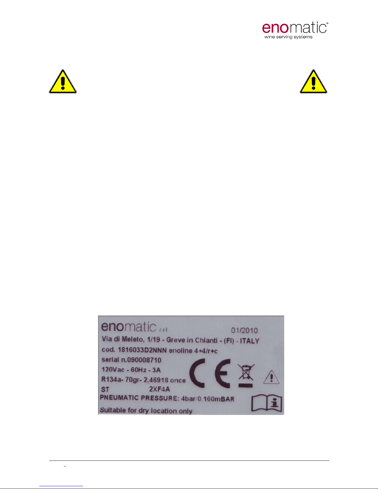
2.
Model
Identification
Every
Enomatic
model
is identified with a unique serial number printed on a
D
ata
L
abel
.
There are two Data Labels on the machine: one is on the rear panel, close to
electric socket, the other one is on the fro
ntal side and lays beneath the drop
tray.
The D
ata
L
abel
is the only means of identification authorised by the
manufacturer and it contains all the data needed by the manufacturer to
provide prompt and clear information concerning any technical aspects and to
facilitate the replacement of parts.
AVOID DAMAGE OR REMOVAL OF THE DATA
LABEL
.
Example:
UM.02
ENOLINEWINE CARD
Page
5
of
46
Rev 0
8,
Ma
y 20
10
3.
Warnings
During operation it is essential to pay attention to these safety requirements to avoid
the risk of fire, electric shocks or other
incidents.
1. Before operating the Enomatic Wine Serving System, carefully read the
instructions contained in this Operating Manual and all other documentation you
received.
2. Do not immerse the electrical cord, plugs or the Enomatic model in water or any
ot
her liquid.
3. Be extra careful when operating the Enomatic Wine Serving System in the
presence of children.
4. Always unplug the Enomatic model from the electrical socket and let it cool down
before carrying out extraordinary maintenance operations.
5. Do not operate the Enomatic model if the electrical cord, plug or any other parts
are damaged or broken, but rather remove it immediately pulling it out of plug
and contact your local distributor.
6. Do not use electrical appliances inside the food storage compartments of the
appliance, unless they are of the type recommended by the manufacturer.
7. For any repairs contact only Service Centres authorised by the manufacturer or
supplier and insist to get only original spare parts. Failure to comply with the
above may harm
persons, damage property and will invalidate the Warranty.
8. This appliance is not intended for use by persons (including children) with reduced
physical, sensory or mental capabilities, or lack of experience and knowledge,
unless they have been given supervision or instruction concerning use of the
appliance by a person responsible for their safety. Children should be supervised
to ensure that they do not play with the appliance
.
9.
Do not operate the Enomatic Wine Serving System outdoors.
10.
Avoid the electrical cord hanging down the supporting surface (table, counter,
etc.) and from coming into contact with hot surfaces. Do not place the Enomatic
model on top of its electrical cord. Never connect a damaged cord, but ask your
local distributor for a spare part. Us
e original spare parts only.
11.
Keep the Enomatic Wine Serving System far away from heat sources.
Keep
ventilation openings, in the appliance enclosure or in the built
-
in structure, clear of
obstruction
.
12.
Before plugging the Enomatic model into the electrical
socket, check that the main
switch General is set to 0 (off) mode.
13.
Before supplying the Enomatic model, check the voltage indicated on the Data
Label, it has to correspond to your country s standard voltage supply value. You
may require an adapter to
plug the cable into your electrical socket.
14.
Do not clean with corrosive detergents or scraping tools. Use only a soft damp
cloth.
4.
Transportation and Storage
Because of the weight and size of the
Enomatic
models
, two people are needed for transportation
.
To avoid damages, it is necessary to take big care during loading and unloading
operations. It is necessary to lift according to the symbol found on the
cardboard package. It is important that
the
Enomatic
models are not placed on
top of each other and
that the right vertical position (indicated by arrows on the
package) is maintained at all times. Avoid shaking or turning the
Enomatic
models
upside down.

UM.02
ENOLINEWINE CARD
Page
6
of
46
Rev 0
8,
Ma
y 20
10
5.
Unpack
When you
removed the packaging, check that the Enomatic model has not been
damaged during transport. If you have any doubts, do not operate the
Enomatic model
and quickly contact your Enomatic distributor in order to define
a supervising visit. Please make sure that following items are included in the
delivery:
- 1
x
-
Enoline, 4 bottles capaci
ty or
1x
Enoline, 8 bottles capacity;
-
1x
-
Enoline Wine Card
Series
1
-
User and Maintenance Manu
a
l;
-
5x
-
plastic straws
or
10x
plastic straws
;
-
2x
-
steel holders to secure Enoline to the wall;
-
1x
-
Ø 10mm pipe for water drainage;
-
1x
electrical cor
d;
-
1x
spirit level;
-
1x
-
tap seal
s
kit;
-
2x
-
fuses;
Never leave the packaging contents (plastic
bags, foamed polystyrene, nails, etc.) within
the reach of children, since they are a source
of potential danger. Please be eco
-
friendly and
recycle
the packaging components.
Above
-
mentioned operations
must be run by skilled personnel only and authorized by the
Manufacturer.
6
.
Installation
For an optimum installation, a technical inspection is needed where the
installation will be performed, in order to establish the correct positioning,
ensure
there is a suitable space for the location of the inert gas cylinder
(
nitrogen
or argon) and air compressor (if required)
and
an earthed
electrical
socket which complies with the regulations.
1.
After unpacking
your Enomatic Wine Serving System, place it on a solid
desk
or holder
,
between 800 and 1300mm from floor. The surface where the
dispenser will be placed must be made by fire
-
extinguisher materials.
2. Please consider a 300mm clereance on fridge
compressor
side and 50mm aback in order to ensure
proper exhaust
air
exchange.
3. Check the stance and correct it if necessary actin
g
on proper adjusting foot/feet. Refer to delivered
spirit level for accurate placement.
4. Secure the machine through supplied holders to th
e
wall if needed.
5. Tight pressure regulator (6434) to nitrogen or argon
tank, using supplied seal (if previewed).
6. Connect FOODGRADE LLDPE 4mm pipes in order to
bond machine and nitrogen source.
7.
Connect the electrical cord
and turn the machine on.
8. Open the nitrogen or argon tank and turn the outlets
levers on vertical position; the gas will then reach
the machine.
9. From now on Your Enomatic wine Serving System is ready for bottles
engagements. Enjoy your wines!!!!

UM.02
ENOLINEWINE CARD
Page
7
of
46
Rev 0
8,
Ma
y 20
10
6.1
Parts of the Enomatic Wine Serving Syste
m
1
Bottle space
2
Bottle Piston with cover
3
Serving Buttons
4
Serving Spouts
5
Thermostat (available on temperature models only)
6
Wine card Display
7
Wine Card Reader slot
8
Price displays
9
Enoprog socket
(see picture aside
)
Enoline 4+4 Wine Card
1
Red Wines b
ottle space
2
Bottle Piston with cover
3
Serving Buttons
4
Serving Spouts
5
Thermostat for red wines bottle space
6
W
ine card Display
7
Wine Card Reader slot
8
Price displays
9
Enoprog socket
(see picture aside
)
10
-
Thermostat for white wines bottle space
11
White wines bottle space

UM.02
ENOLINEWINE CARD
Page
8
of
46
Rev 0
8,
Ma
y 20
10
6.2
Electrical supply
The
eno
line models operate at either 110 or 220V
de
pending upon the country. Before connecting
these models to the electrical sockets, check the
voltage detailed on the Data Label on the back
panel. The room temperature
eno
line models have
one main switch on the power panel (photo on
right) which also cont
ains the fuses
(left side)
.
Ensure enough access to switch
es, fuses
and cable plug.
The temperature controlled
eno
line models have three (3) switches located on
the back
refer to the photo below. The enoline models feature also external
RJ45 connecti
ons to enable them to be connected to a data network.
For all switches Ois OFF and
or
|
is ON.
The Enomatic models must be connected to a supply system equipped with an
effective earth connection in accordance with the rules and provisions
prescribed by law.
Switch all switches to Omode. Connect the electrical supply cord. With a
ll
models black main switch turns power onto the model.
For temperature controlled enoline (right
side reference)
models secondary switches are:
Right side - turns on and off the compressor for
the temperature control.
Left side - turns on and off the electronics inside
the enoline model.
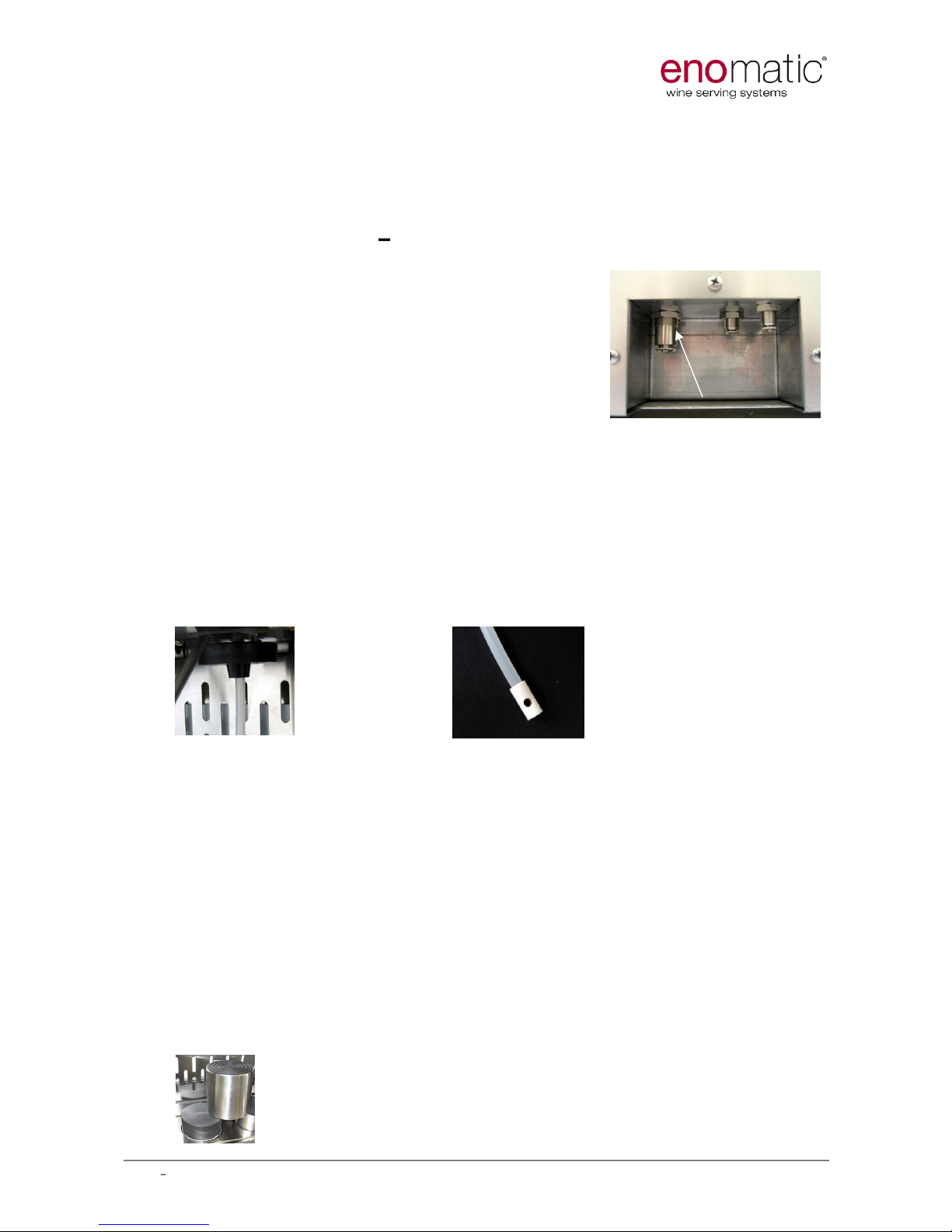
6.3
Gas Line Connections
Two different pressure lines are typically required to operate your Enomati
c
Wine Serving System
, and those are:
Bottle Piston Supply
-
4.0 Bar pressure
Nitrogen or air compressor
Nitroge
n (or Argon) Gas Supply
-
0.16 Bar pressure
4mm pipe connection outlets are located at the back of enoline models, on the
bottom (photo below); 4 bar line (bottle pistons movements) can be supplied
by compressed air coming from an external source (not p
rovided), as well as by
nitrogen.
Use certified FOODGRADE materials and
LLDPE pipes for nitrogen (argon)
connections

UM.02
ENOLINEWINE CARD
Page
9
of
46
Rev 0
8,
Ma
y 20
10
6.3.1
Bottle Piston Supply
The 4 bar line supplies the Bottle Pistons to raise and hold the bottles upwards,
in order to ensure an air tight seal
on
the Tap. It is recommended to use a
compressed air supply in case of more than 12 bottles installations
.
4.0 Bar pressure must be provided from either:
an air compressor
the Nitrogen (or Argon) Gas supply cylinder
a Nitrogen Generator (recom
mended for very large installations)
If an air compressor is used, the air source must be equipped with a sluice
gate, a pressure regulator
(4
Bar
outlet required
) and a filter to avoid impurities
blocking the pneumatic circuits. A moisture trap is also required in humid
environments.
Connect the Bottle Piston Supply to the Enomatic model by firmly pushing the
4mm FOODGRADE LLDPE pipe
into the friction fitting.
6.3.
2
Nitrogen
(
Argon) Gas Supply
Main purpose for the use of Nitrogen or Argon is to preser
ve
wines from oxidation processes. As soon as a bottle is engaged
into the machine, Nitrogen is inflated into it and the preservation
starts. Second main purpose for Nitrogen is to dispense wines
from the bottle to the Serving Spout. It is also used to clean the
Serving Spout after each serve.
Foodgrade Nitrogen (or Argon) Gas of greater than 99.5% purity
must be used. This is typically supplied as a compressed gas
stored in cylinders, at high pressure. The pressure varies
between countries but it is typically between 150 or 200 Bar.
Alternatively a
certified n
itrogen generator can be used.
The Nitrogen (or Argon) Gas cylinder must be secured in a
vertical position and stored in a ventilated space. It mu
st
be connected to a
regulator to reduce the pressure to 0.16 Bar (that value may vary depending
installation features)
.
The following procedure must be carried out when connecting the Nitrogen (or
Argon) Gas cylinder:
1. Ensure the regulator outlet valves are in the
closed position (as shown in the p
hoto).
2. Insert the seal (if previewed) and tight
the
regulator system to the cylinder and ensure an
air
-
tight connection.
3. Open the cylinder valve, note down the
indicated max pressure value, and close the
cylinder; the value doesn t have to decrease
withi
n 15 in order to avoid risk of leak.
4. Connect the Nitrogen (or Argon) Gas Supply
from the regulator to the outlets on the Enomatic model by firmly pushing
the 4mm FOODGRADE LLDPE pipe into the friction fitting, on the Enomatic
model and
on
the regulator
as
well
.
5.
Completely open the valve of the cylinder.
6.
Open the regulator levers
.
7. Note down the indicated max pressure value, and close the cylinder; the
value doesn t have to decrease within 15 in order to avoid risk of leak.
UM.02
ENOLINEWINE CARD
Page
10
of
46
Rev 0
8,
Ma
y 20
10
8. Check that the pressure on the low pressure gauge is correct= 4 bar.
Also
check every 6
-7
days the pressure of the cylinder.
9. When the tank is almost empty and change is required, close all inlets and
outlets and pull the safety valve ring to discharge residual pressure; loose
mano
meter bolt and replace the tank.
6.4
Water
Drain
age
E
noline Temperature Controlled
models only
A condensate drain tube (10mm O/D) must be
connected into the back of the temperature
controlled enoline models and discharged to a
permanent drain or into a bottle that is emptied
regularly.
7
Operating Instructions
Turn on the power.
Switch on main black switch and two secondary switches (for temperature
controlled enoline only).
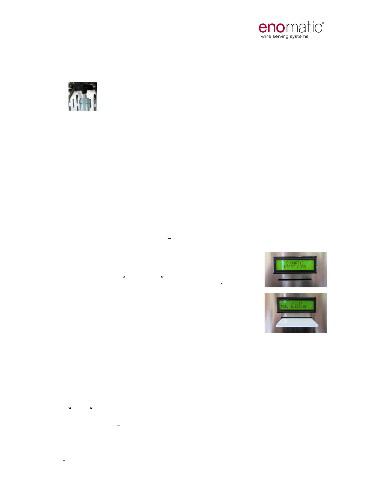
7.1
Inserting the Bottle Tube
Insert the Bottle Tube into the centre of each Tap by pushing it firmly to create
a secure fit (pic A).
PIC A
PIC B
The Bottle Tube has a filter (pic B) to prevent sediment from red wines entering
the Tap valve. The Bottle Tube should extend to the bottom of the bottle.
However, for
he
avy
sediment red wines, it is recommended to cut
the
tube shorter, in order not
to reach the bottom of the bottle; this is to
avoid the
sediment entering the tap.
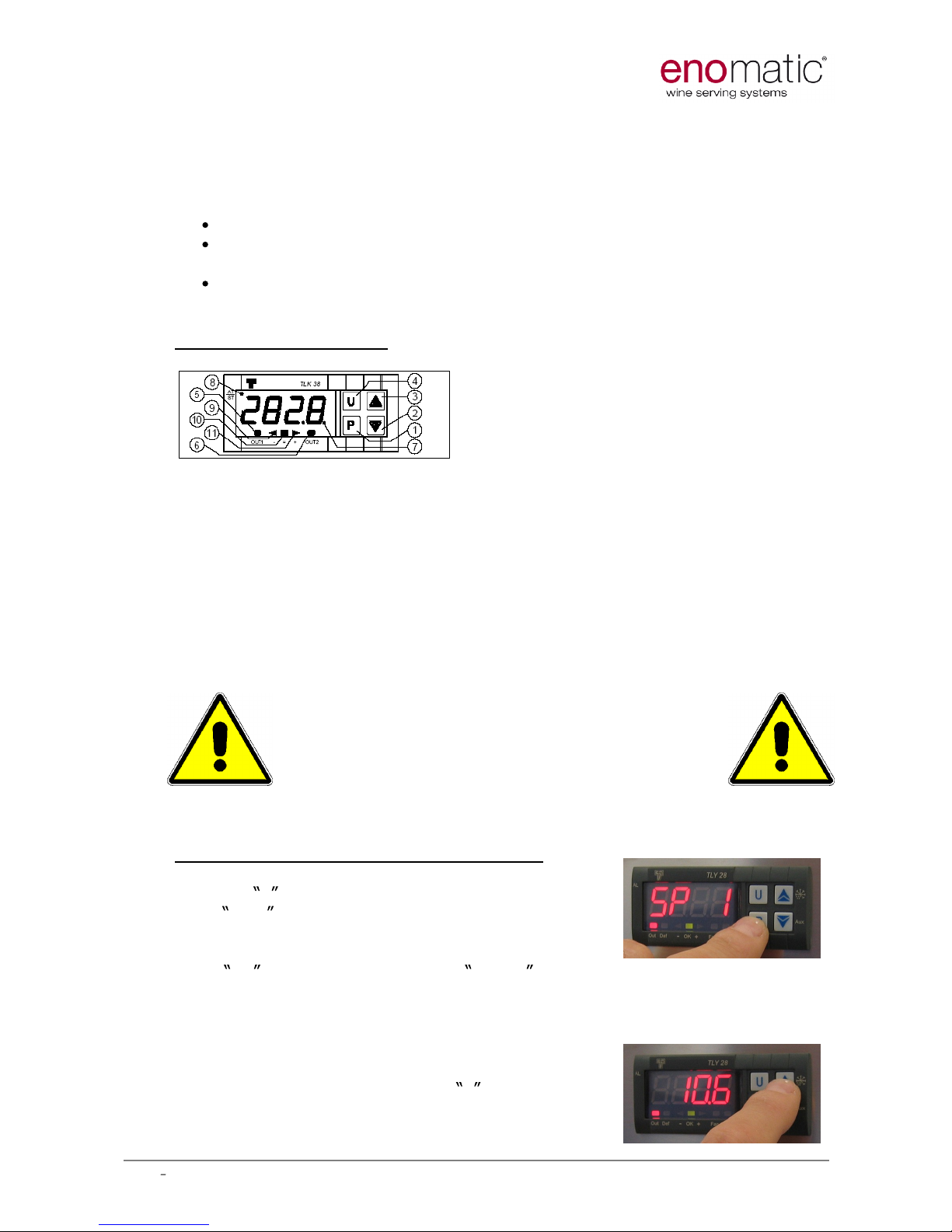
7.2
Loading the Bottle
Open the bottle, remove any eventual foreign object from bottle neck u
pper
part and slide the Bottle Tube inside the bottle while lifting the bottle towards
the tap. Place the bottle on the piston (pic C
).
Insert a Technical Card (*) into
the slot and firmly press the central button above the bottle you desire to
engage.
Th
e maximum bottle size is 360mm high. The Enomatic model is
supplied with plastic packers below the bottle piston covers. These packers can
be removed to fit the tallest bottles
, or added to fit shortest ones.
PIC C
UM.02
ENOLINEWINE CARD
Page
11
of
46
Rev 0
8,
Ma
y 20
10
Ensure that the neck of the bottle
lines u
p to
the conical neck of the Tap (
pic D
)
in order to enter it.
Some
bottles
may
feature
particular cork
-
necks
dimensions
;
should they be too large, please use the apposite large-
corks
-adapter (6510
item
code
).
PIC D
Once the bottle has been engage
d,
turn it lightly on its axis in order to increase
and improve air-tight on the neck seal. The lights above the bottle will flash.
Select a wine from Enosoft database to match to it
(*)
, and insert a User Card
with sufficient money on (*). Hold a glass be
neath
the Serving Spout
,
push the
Serving Button and verify the supply of the wine. Repeat the instructions above
for all bottle
s,
the same actions to lift down engaged ones. To calibrate
the
serve, insert the Technical Card and keep buttons #1 and #3 pressed (about
4sec); the display will show
Cali
and then 100. Hit central button to pour and
measure the serve, adjusting 100ml value on display by tapping buttons #1 (to
decrease) and #3 (to increase); repeat till 100ml are poured, then remove the
Technical
Card to store the value; repeat same procedure for all taps.
Please remember to remove the frontal Plexiglas panel only when
loading/replacing the bottle, and in any case no longer than strictly required
time. Please remember also to load in your Enomatic Wine Serving System
already cold white wines.
(*
): to get information about Technical C
ard
,
User Card and Enosoft in general
,
pleas
e refer to
manual
UM.13
enosoft 2.0
.
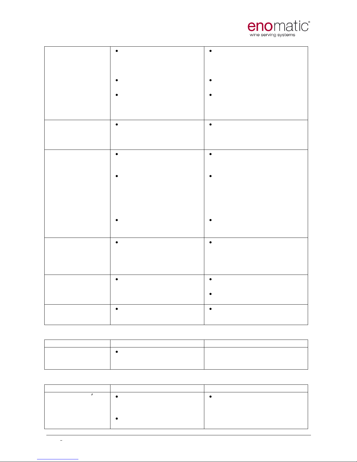
7.3
Use of the Enomatic Wine Serving System
When no card is inside the card slot, the name of the
installation and insert card are shown; that is the re
st
condition.
In order to activate a dispensing, it s necessary
to insert a card with a sufficient amount of money and hit
the desired volume/price button. The name of the selected
wine will be shown on main display.
The
system will
decrease relative price from your card balance and will pour
the wine. Remaining credit on the card is shown on main
display.
7.4
Replacing Bottles
In order to lower the Bottle Piston, insert a T
echnica
l
Card (*) and press firmly
central button related to the bottle you want to remove
.
Remove the empty bottle and the straw inside. Clean thoroughly the straw
under a flush of water.
Repeat procedure from 7.2 to engage another bottle. Press the central bu
tton
to confirm same wine indication when the display above the bottle will display
SAME , or remove the Technical Card to assign a new wine.
(*):
to get information about Technical Card and User Card, please refer to
manual
UM.13
enosoft 2.0
.
UM.02
ENOLINEWINE CARD
Page
12
of
46
Rev 0
8,
Ma
y 20
10
7.5
Change
the
Temperature
Set Point
(enoline temperature controlled models only)
If your enoline is a temperature controlled model it will typically be supplied
pre
-
programmed to:
8°C for refrigerated models (down to 7°C is possible), or
18°C for climate controlled models (between 7°C to 20°C range is
possible)
, or
8°C and 18°C for dual climate models.
If you wish to change these temperatures, please refer to the following
instructions.
Front Panel Description
1
- Key P : This is used to access the programming parameters and to confirm
selection.
2
-
Key DOWN
: This is used to decrease the values to be set and to select the
parameters. If the key is held down, the controls return to the previous
programming level until it exits the programming mode.
3
- Key UP : This is used to increase the values to be set and to select the
parameters. If the key is held down, the controls return to the previous
programming level until it exits the programming mode.
The other buttons and functions are not required to change the
temperature set
point.
Please settle the Enomatic Wine
Serving System in environments
with temperature range between
10°C and 30°C, and relative humidity
lower than 60%.
Programming
the Temperature Set Point
Push key P , then release it and the disp
lay will
show SP 1 . (If you
press the button
too
long it will
enter another menu;
to return to the SP mode, wait
for
10 seconds)
.
To modify t
he temperature value,
press
UP
key to increase it or the DOWN key to decrease it. These keys
change the valu
e one
-
by
-
one digit but if they are pressed longer than three
seconds, the value increases or decreases rapidly; after two seconds in the
same condition, the changing speed increases in order to allow the desired
value to be reached rapidly.
Adjust until the desired temperature value has been
reached.
Exit by pushing key P and after 15
seconds the set temperature will be displayed.

UM.02
ENOLINEWINE CARD
Page
13
of
46
Rev 0
8,
Ma
y 20
10
Programming the Temperature set points on dual climate models
Dual climate models involve two separated rooms where two diff
erent
temperatures can be set, in order to typically engage 4 red wine bottles and 4
white wine bottles. Red wine bottle space thermostat allows to modify the
temperature between 16°C and 20°C, whilst white wine bottle space thermostat
permits a settable range between 7°C and 20°C. Upper thermostat (TLK38)
refers to red zone bottle space, while lower one (TLY28) is about white wine
bottle space. White wine bottle space is the one closer to thermostat (right side
if your model is right hand compressor as in picture at page 7). White wines
must be already cold before being engaged into the dispenser, and the frontal
Plexiglas panel must be removed just for strictly necessary replacement bottle
time.
9
. Troubleshooting
This guide is to provide a quick support in case of faulty behaviours. I n case
the problems remain, please contact your local eno
matic
dealer.
Full list is available on www.enomatic.it
Trouble
Origin
Solution
There is a leak of
nitrogen
(or argon)
The bottle is not properly
engaged.
One
or more too short
bottle was engaged and
the sealing on the tap is
not correct.
If no bottle is engaged a
valve inside the tap
might be stucked.
Tank seal is missing (if
previewed).
Tank or pipes joints are
loose.
Check all the bottles triyng
to he
ar a whistle coming
from the necks or wet your
finger and surround them.
Check all the bottles are
pushed upwards and tight
against the seals.
Install cylindric adapter
(code 6012) between bottle
and piston.
Manually move the tap seal
downwards in order
to
release the valve anch for
leaks.
Puor cleaning
solutions.
Remove the manometer, fix
the seal and tight the bolt.
Check correct pipe fixing
and jointing.
Check manometer
tightening.
The machine
doesn t switch on.
Power failure.
Switch(es) is (are
) off.
Fuses are burned.
Plug the machine to a
power supply.
Switch on.
Change the fuses.
UM.02
ENOLINEWINE CARD
Page
14
of
46
Rev 0
8,
Ma
y 20
10
Bottle engagement
indicator led(s) is
(are) off.
Only some bottle
engagement
indicator leds are
on.
Bottle was engaged
while the machine was
off.
Bottle is m
issing.
Tap sealing is not
pushing the microswitch
behind the tap. (for off
ones)
Remove the bottle and
insert it while the machine
is on.
Engage the bottle.
Push manually upwards the
tap sealing checking the
click of the switch.
Bottle engagement
ind
icator led
switches off when
bottle is not empty.
Wrong operative
parameters.
Check parameter # 5 (full
bottle capacity) in
programmino mode.
Pouring is not
fluent.
Internal straw is not
properly inserted.
The filter at the bottom
of the internal straw i
s
stucked (especially with
sediment or aged
wines).
Tank is almost empty or
pressure is not enough.
Remove the bottle and fix it
properly.
Remove the bottle and
clean the filter.
Change the tank.
Wine drops falling
from the spouts.
Some wine sediments or
cork pieces are blocking
the dispensing valve.
Pour citric acid solution to
remove all the sediments
and foreign objects from the
valve.
Pistons fall down.
Loss or leak of pressure
on compressed
air/nitrogen supply pipe.
Check correct duty press
ure
(4 Bar).
Check the pipe not to be
pressed or pricked.
Wine bubbles in the
glass while pouring.
Wine is falling on the
bottom of the glass.
Lean the glass towards the
spout.
T
EMPERATURE CONTROLLED MODELS
Trouble
Origin
Solution
Set temperature is
n
ot reached.
Not enough air
circulation.
Check the free space aside the
compressor engine (300mm)
and provide it if missing.
WINE CARD MODELS
Trouble
Origin
Solution
Machine doesn t
react when a
winecard is
inserted.
The winecard is not
properly inserte
d.
The winecard reader is
not activated.
Insert the winecard with the
chip facing downwards.
Activate the
card reader
through Module Card.
UM.02
ENOLINEWINE CARD
Page
15
of
46
Rev 0
8,
Ma
y 20
10
10.
Maintenance and Cleaning
A frequent and
severe
dispensing taps cleaning is
necessary to maintain you
r En
omatic Wine
Serving System in full performances
and
to grant wine flavours preservation. If
you respect the maintenance
programme your Enomatic Wine Serving
System will be efficient fo
r
long time. For repairs and
maintenance, in case of faults or faulty o
perations, call
only an authorised after
-
sales service centre, or contact
your local Distributor.
10.1
Daily Maintenance
On a daily basis:
-
clean the drip tray with a damp sponge.
-
clean the Serving Spout by immersing it in water and then rinse thoro
ughly.
-
clean the
bodywork with a non
-
abrasive cloth.
10
.2
Bottle Tube and Tap Cleaning
Dispensing taps and internal straws must be cleaned EVERY 10 POURED
BOTTLES PER DISPENSING POSITION (please note the chart available at the
end of this manual to
be ticked at any bottle engagement for tracking)
. A
n ideal
time to clean the entire Bottle Tube and Tap is when a bottle is being changed
this is because a partly used bottle can not be reinstalled into the system (it will
contain air
, and preservation
won t be effective); act as follow:
replacing the wine with a bottle containing diluted citric acid (3-4
teaspoons each 750 ml of water
, ca. 15
-
20 grams of product
);
run some citric acid cleaning solution pours , wait 10 minutes and repeat
the
supply (serve approximately 300
mls
each time). Wait a few more
minutes and remove the bottle containing the cleaning solution;
insert
a bottle of clean water and flush the Bottle Tube and Tap with
the water (serve approximately 200mls);
replace the water with a new
bottle of the wine to be served and supply a
serve in order to fill the empty Bottle Tube.

UM.02
ENOLINEWINE CARD
Page
16
of
46
Rev 0
8,
Ma
y 20
10
10
.3
Extraordinary maintenance
An extraordinary maintenance must be run every six months in order to ensure
perfect cleaning on the ducts and to avoid wine sediments all over them.
Change the wine bottle with one containing chlorine based cleaner
non
smelling (diluted in clean water in accordance with the manufacturers
instructions);
supply a few serves of the chlorine based cleaning solution, wait 10
minutes a
nd
repeat the supply (serve approximately 100mls). Wait
5 minutes and remove the
bottle containing the cleaning solution;
replace the bottle with a bottle containing diluted citric acid (10 grams of
citric acid added to a wine bottle of clean water) and
serve approximately
150mls;
install a bottle of clean water and flush the Bottle Tube and Tap with
the water (serve approximately 200mls);
R
eplace the water with a new bottle of the wine to be served and supply a serve
in order to fill the empty Bottle
Tube.
Execute an intense cleaning before leaving your
Enomatic Wine S
erving System not
operative
longer than three days.
Please note that
dispensing
sweet
or
particularly aged
wines
may result
into
severe
wine
-
deposit inside the
d
ucts. Intensify cle
aning through
citric acid solutions in
case.

UM.02
ENOLINEWINE CARD
Page
17
of
46
Rev 0
8,
Ma
y 20
10
11.
Technical Characteristics
enoline 4
MODEL
enoline 4
rf/cc
enoline
8
enoline 8
rf/cc/4+4
Height
643
643
643
643
Width
530
750
970
1190
Size (mm)
Depth
200
200
200
2
00
Diameter
- - - -
Weight (kg)
25
40
45
65
Voltage (V)
110/220
110
220
110/220
110
220
Electrical
Frequency
(Hz)
50
/60
60
50
50
/60
60
50
Performance
Watts (W)
30
150
150
30
150
150
Fuses ( NOT
COVER BY
WARRANTY)
(Amps)
2 x
2 Amp
2 x
8
Amp
2 x
4
Amp
2 x 2
Amp
2 x 8 Amp
2 x 4
Amp
Nitrogen or Argon Gas
Supply Pressure (Bar)
4.0 single
4.0 single
0.16
0.16
Air Supply Pressure (Bar)
connection
connection
4.00
4.00
R-
134°=
96(80gr.dual)
Refrigerant
- R-
134°=80
gr
-
Electronic
Electronic
Refrigeration
Method to
change
temp.
-
Controller
- Controller
Details
Automatic
via
Automatic via
-
Electronic
-
Electronic
Defrost
method
Controller
Controller
Temp.
display
-
Digital
-
Digital

UM.02
ENOLINEWINE CARD
Page
18
of
46
Rev 0
8,
Ma
y 20
10
DECLARATION OF COMPLIANCE
Manufacturer:
eno
matic
Address:
Via di meleto 1/19 50027 Strada in Chianti Firenze Italy
Being the manufacturer, hereby declares within its own responsibility that the:
AUTOMATIC WINE SERVING SYSTEM,
m
odel
Enoline,Enomodule, Enoround, Enomove
To which this statement refers to, if used according to the Operating Manual, conforms to the
following CE legal standards:
CEI EN 60335
-1 -
modification A2, A13,
A14, A15, A16
Household and similar electrical appliances and similar . General
norm file n. 4196C
-
CEI EN 50081
-
1
Electro-Magnetic Compatibility general emissions standards Part
1:residential, commercial and light industry environments. File
3215 June 1997
-
CEI EN 50082
-
1
Electro-
Magneti
c Compatibility general immunity standards . Part
1: residential, commercial and light industry environments. File
4498 May 1998
-
CEI EN 61000
-3-2 Electromagnetic Compatibility EMC. Part 3: limits. Section 2:
limitations of voltage fluctuations and f
licker in low voltage supply
systems (appliances with rated current <16A per phase). File 4749
C
-
CEI EN 61000
-3-3 Electro-Magnetic Compatibility EMC .Part3: limits. Section 3
limiting in voltage fluctuation and of flickers in low voltage feeding
sys
tems for appliances with nominal current <16A . File 2650E
Also declares that it conforms with the requisite Directives:
-
Low Voltage Directive
2006/95
EC
( Directive: regulation concerning the approach of State
Members laws regarding the electric ma
terial destined to be used within certain voltage limits)
-
Electro
-
Magnetic Compatibility
2004/108
EC
(Directive regarding the approach of State
Members laws concerning about electro-
magnetic compatibility
Also declares that it is formally conformed
to all the Directives of the MACHINES REGULATION
CE 98/37as, following the comma 2 enclosed 1, the risk of the machine is to be considered
MAINLY electric, therefore is enough to fulfil the above regulations 2006
/95
EC
/ 2004/108 ce
eno
matic srl
08
________________________
the last 2 digit of the year of production
Via di Meleto 1/19
50027 Strada in Chianti
Firenze Italy
P.I. 01066310523

UM.02
ENOLINEWINE CARD
Page
19
of
46
Rev 0
8,
Ma
y 20
10
The
Enomatic
model
s
compl
y
with the provisions of the following community directive
s:
Low
Voltage
Directive
73/23
/EEC and Directive
93/68
/EEC
Machinery
Directive 98/37
/EEC
EMC Directive 89/336
/EEC and Directive 93/68/EEC
The
Enomatic
model
s
comply
with the following technical regulations:
EN 60335
-
1 2
a
Edition
EN 50081
-
1 1
a
Edition
E
N 50082
-
1 2
a
Edition
EN 610003
-
2 2
a
Edition
EN 610003
-
3 1
a
Edition
The Microprocessor
-
based Digital Electronic Controller
TLK38
complies with the following
technical regulations:
ECC directive EMC 89/336 (EN 61326), ECC directive
LV 73/23 and 93/68 (EN
61010
-
1)
C-
UL (file n. E206847)
The Microprocessor
-
based Digital Electronic Controller TLY28 complies with the following
technical regulations:
ECC directive EMC 89/336 (EN 61326), ECC directive LV 73/23 and 93/68 (EN
61010
-
1)
All Enomatic models desc
ribed
in this manual are
SUITABLE FOR DRY LOCATIONS ONLY
In accompliance to ISO
-
7000
Graphical Sym
bols for use on equipment

UM.02
ENOLINEWINE CARD
Page
20
of
46
Rev 0
8,
Ma
y 20
10
IMPORTANT
NOTICE FOR THE USER
As prescribed by Art.13 D.L
#151, July 25
th
2005:
Attuazione delle Direttive 2002/95/CE, 2002/96/CE e 2003/108/CE, relative
alla riduzione dell uso di sostanze perico
lose nelle apparecchiature elettriche ed
elettroniche, nonché allo smaltimento dei rifiuti
In respect of
2002/95/EC, 2002/96/EC and
2003/108/EC, about the reduction
of dangerous material use contained in electric and electronic equipments, and
about wast
e disposal.
The symbol showing a crossed litter, labelled on the device and/or on the
packing, is to mean the need to separately dispose the equipment from normal
domestic waste. User must therefore forward the dead equipment to an
authorized electric and
electronic waste collection, in order to ensure
environment respectful disposal. User can also forward the dead equipment to
an authorized dealer and ask for substitution in case of same machinery
purchase.
A correct disposal and treatment of expired equ
ipments will result into reduced
risks for population and increased environment respect. Recycling process will
be easier.
Illegal disposal is a crime persecuted by law.
This manual suits for next models
1
Table of contents
Languages:


