enphase HCS-40 User manual

HCS EVSE Installation
and Operation Manual
EN
VERSION 3.0
JANUARY
FOR PRODUCT FAMILIES:
HCS-
HCS-
HCS-
HCS-
© 2024 Enphase Energy Inc. All rights reserved. January 2024
1140-00277-03
2
HCS Installation and Operation Manual
Corporate headquarters contact information
Enphase Energy Inc.
47281 Bayside Pkwy, Fremont, CA 94538, United States
Ph: +1 (707) 763-4784
https://support.enphase.com/s/contact-us
To view the latest version of the product warranty, please visit:
https://enphase.com/warranty/us
To register your EV charger for warranty, please visit:
https://enphase.com/ev-chargers/warranty-registration
To view the latest version of this manual, please visit:
https://enphase.com/installers/resources/documentation/ev-chargers
© 2023 Enphase Energy. All rights reserved. Enphase, the e and CC logos, IQ, and certain other marks listed at https://enphase.com/
trademark-usage-guidelines are trademarks of Enphase Energy, Inc. in the US and other countries. Data subject to change.
Note:
This user manual includes the latest information at the time of printing. Enphase Energy, Inc. reserves the right to make
changes to this product without further notice. Changes or modications to this product by other than an authorized
service facility may void the product warranty.
Contact Enphase Support with any questions about the use of this product. 877-797-4743.
WARNING: This product can expose you to chemicals, including
Carbon Black, which is known to the State of California to cause
cancer. For more information go to: www.P65Warnings.ca.gov

© 2024 Enphase Energy Inc. All rights reserved.
January 2024
140-00277-03
3
HCS Installation and Operation Manual
Contents
Important Safety Information ................................................................................................................ 5
Instructions Pertaining to a Risk of Fire or Electric Shock ........................................................... 6
Additional Instructions for Plug-In EVSE Congurations..............................................................7
Additional Safety Instructions ...........................................................................................................8
FCC Information....................................................................................................................................... 9
Operation .................................................................................................................................................10
Front Panel LED Indications ............................................................................................................
11
Charge Cable Wrap Guidelines ............................................................................................................ 12
Installation - Service Connections.......................................................................................................13
Wiring Instructions (Hardwired)........................................................................................................... 17
Receptacle Instructions (Plug-In EVSE).............................................................................................. 18
Receptacle Safety Instructions (240V Plug Type EVSE)...............................................................19
Grounding Instructions ........................................................................................................................20
Hardwired EVSE Grounding .............................................................................................................20
Plug-In EVSE Grounding...................................................................................................................20
Mounting Procedures............................................................................................................................. 21
EVSE Mounting for Hollow-Wall Construction.............................................................................. 22
EVSE Mounting for Solid-Wall Construction................................................................................. 23
Mounting the
SAE J1772
Connector Holster ...................................................................................... 24
Moving & Storage Instructions............................................................................................................. 25
Optional Features for HCS ................................................................................................................... 26
Maintenance ...........................................................................................................................................27
Enphase Support ................................................................................................................................... 28
Specifications......................................................................................................................................... 29
Revision history......................................................................................................................................
31

© 2024 Enphase Energy Inc. All rights reserved. January 2024
1140-00277-03
4
HCS Installation and Operation Manual
Illustrations
Figures
1. Front panel LED connections ........................................................................................................
11
2. Drape the charge cable loosely around the enclosure.............................................................12
3. 220/240V single phase ..................................................................................................................15
4. 208V three-phase, wye-connected.............................................................................................15
5. 240V three-phase, delta-connected, with center-tap on one leg..........................................16
6. Wiring the EVSE in a junction box.................................................................................................17
7. Preferred orientation of the NEMA receptacles below the plug-in EVSE ..............................18
8. NEMA 6-50R/NEMA 14-50R..........................................................................................................19
9. Mounting the EVSE to a hollow-wall.............................................................................................22
10. Mounting the EVSE to a solid-wall ................................................................................................23
11.
Mounting the SAE J1772 Connector Holster using the exterior wood screws and washers
....24
12. Enclosure dimensions.....................................................................................................................30
Tables
1. Front panel LED information..........................................................................................................
11
2. Service connections for HCS by model.......................................................................................13
© 2024 Enphase Energy Inc. All rights reserved.
January 2024
140-00277-03
5
HCS Installation and Operation Manual
Important safety information
Read this rst
Carefully read these instructions and the charging instructions in your vehicle owner’s handbook before charging your electric
vehicle.
The following symbols may be found in this manual or on labels axed to the Electric Vehicle Supply Equipment (EVSE):
NOTE:
This means pay particular attention. Notes contain helpful suggestions.
CAUTION: This symbol means be careful. There is potential to do something that may result in damage to the
equipment.
WARNING: This symbol indicates danger. You are in a situation that could cause bodily injury. Before you work on any
electrical equipment, be aware of the hazards involved with electrical circuitry and standard practices for preventing
accidents.

© 2024 Enphase Energy Inc. All rights reserved.
6
HCS Installation and Operation Manual
November 2023
IOM-HCS-140-00277-03
Instructions pertaining to a risk of re or electric shock
When using the HCS, basic electrical safety precautions should be followed:
• Use this EVSE to charge electric vehicles equipped with an SAE J1772 charge port only. Consult the vehicle’s
owner manual to determine if the vehicle is equipped with the correct charge port.
• Make certain the EVSE SAE J1772 charge cable is positioned such that it will not be stepped on, tripped over, or
otherwise subjected to damage or stress.
• This product contains no user-serviceable parts. Consult the “Enphase Support” section in this manual for
service information. Do not attempt to repair or service the EVSE yourself.
• Do not operate your EVSE if it or the SAE J1772 charge cable is physically open, cracked, frayed, or otherwise
visibly damaged. Contact a Service Representative for service immediately. Consult the “Enphase Support”
section in this manual for information on the Service Representative in your area.
• Not for use in commercial garages where a COMMERCIAL GARAGE is dened as a facility (or portion thereof)
used for the repair of internal combustion vehicles in which the area may be classied due to ammable vapors
being present (such as from gasoline).
• Do not place ngers inside the coupler end of the SAE J1772 charge cable.
• Do not allow children to operate this device. Adult supervision is mandatory when children are in proximity to an
EVSE that is in use.

© 2024 Enphase Energy Inc. All rights reserved. 7
HCS Installation and Operation Manual
November 2023
IOM-HCS-140-00277-03
Additional instructions for plug-in EVSE congurations
•
240 V plugs are specically designed for occasional relocation, such as moving from one home to another home
.
•
For personal safety, the circuit breaker must be turned o prior to plugging in AND/OR unplugging 240 V
appliances (including this EVSE).
• A
high-quality industrial-grade dedicated NEMA outlet receptacle listed to UL 498 (US) and C22.2 No. 182.3-16
(Canada) standards must be used with your plug type EVSE.
• Before using, make sure the receptacle and plug t tightly.
• Do not use this EVSE with an extension cord or wall plug adapter. Plug this EVSE directly into the receptacle.
We recommend that plug-in EVSEs remain plugged into the receptacle.
• Have an electrician
verify all wiring to the outlet is correct and in compliance with local code requirements
before connecting the EVSE.
•
A worn or defective receptacle can cause the plug to overheat and become a re hazard. Periodically touch
the plug surface during the charge session to see if it is hot to touch. If so, we recommend an electrician check the
connection tightness and replace the receptacle.
•
Ensure that the EVSE is mounted to the wall or placed on a support so it does not hang from the
receptacle
.
Receptacle
s are not designed to support the weight of the EVSE.
•
The EVSE shall be installed so that the power supply cord does not contact the oor when plugged into the outlet.

© 2024 Enphase Energy Inc. All rights reserved. January 2024
1140-00277-03
8
HCS Installation and Operation Manual
WARNING: Turn o power to the EVSE at the circuit breaker panel before moving, servicing, or cleaning the unit.
WARNING: Always turn o input power to the EVSE at the circuit breaker panel prior to plugging into or unplugging
from a wall socket.
NOTE: VENTILATION - Some electric vehicles require an external ventilation system to prevent the accumulation
of hazardous or explosive gases when charging indoors. Consult the vehicle owner’s manual to determine if your
vehicle requires ventilation during indoor charging.
NOTE: Vehicles that conform to the SAE J1772 standard for communication can inform the charge station
that they require an exhaust fan. The EVSE is not equipped to control ventilation fans. Do not charge the vehicle with
the EVSE if ventilation is required.
CAUTION:
DO NOT CHARGE a vehicle indoors if it requires ventilation. Contact a Service Representative for information.
Save these instructions for future reference.
Additional safety instructions

© 2024 Enphase Energy Inc. All rights reserved.
January 2024
140-00277-03
9
HCS Installation and Operation Manual
FCC information
This device complies with Part 15 of the FCC rules. Operation is subject to the following two conditions: (1) This device
may not cause harmful interference, and (2) This device must accept any interference received, including interference
that may cause undesired operation.
Any changes or modications to the module or host not expressly approved by the party responsible for compliance
could void the user’s authority to operate the equipment.
This product has been designed to protect against Radio Frequency Interference (RFI). However, there are some
instances where high-powered radio signals or nearby RF-producing equipment (such as digital phones, RF
communications equipment, etc.) could aect operation.
If interference to the EVSE is suspected, the following steps should be taken before consulting an Enphase Sales or Service
Representative for assistance:
1. Reorient or relocate nearby electrical appliances or equipment during charging.
2. Turn o nearby electrical appliances or equipment during charging.
CAUTION: Changes or modications to this product by other than an authorized service facility may void
FCC compliance.

© 2024 Enphase Energy Inc. All rights reserved. January 2024
1140-00277-03
10
HCS Installation and Operation Manual
Operation
The HCS is a compact wall or pedestal-mounted EVSE that provides the Plug-in Hybrid or Battery Electric Vehicle (together
Plug-In Electric Vehicles, or “PEV”) user with a safe and manageable link between the power grid and the PEV. Both
hardwired and plug-in HCS versions are available.
To use the HCS, simply unwrap the charge cable and plug the SAE J1772 connector rmly into the vehicle's charge port.
Normally, the vehicle will immediately request a charge using a special communication line in the cable. Within a few
seconds, the Green “Charging” light on the face of the HCS will turn on, and the charging cycle will begin. After an average
driving day, the vehicle battery pack will require several hours to recharge completely. Charging overnight is the most
convenient way to maintain healthy batteries and ensure the vehicle’s full range will be available for the next day.
When the vehicle has stopped charging, the Green “Charging” light on the HCS will turn o. To remove the connector head
once a charge cycle has completed (or to interrupt a charge in progress), press and hold down the latch release lever on the
connector handle, then unplug the connector from the vehicle charge port.
© 2024 Enphase Energy Inc. All rights reserved.
January 2024
140-00277-03
11
HCS Installation and Operation Manual
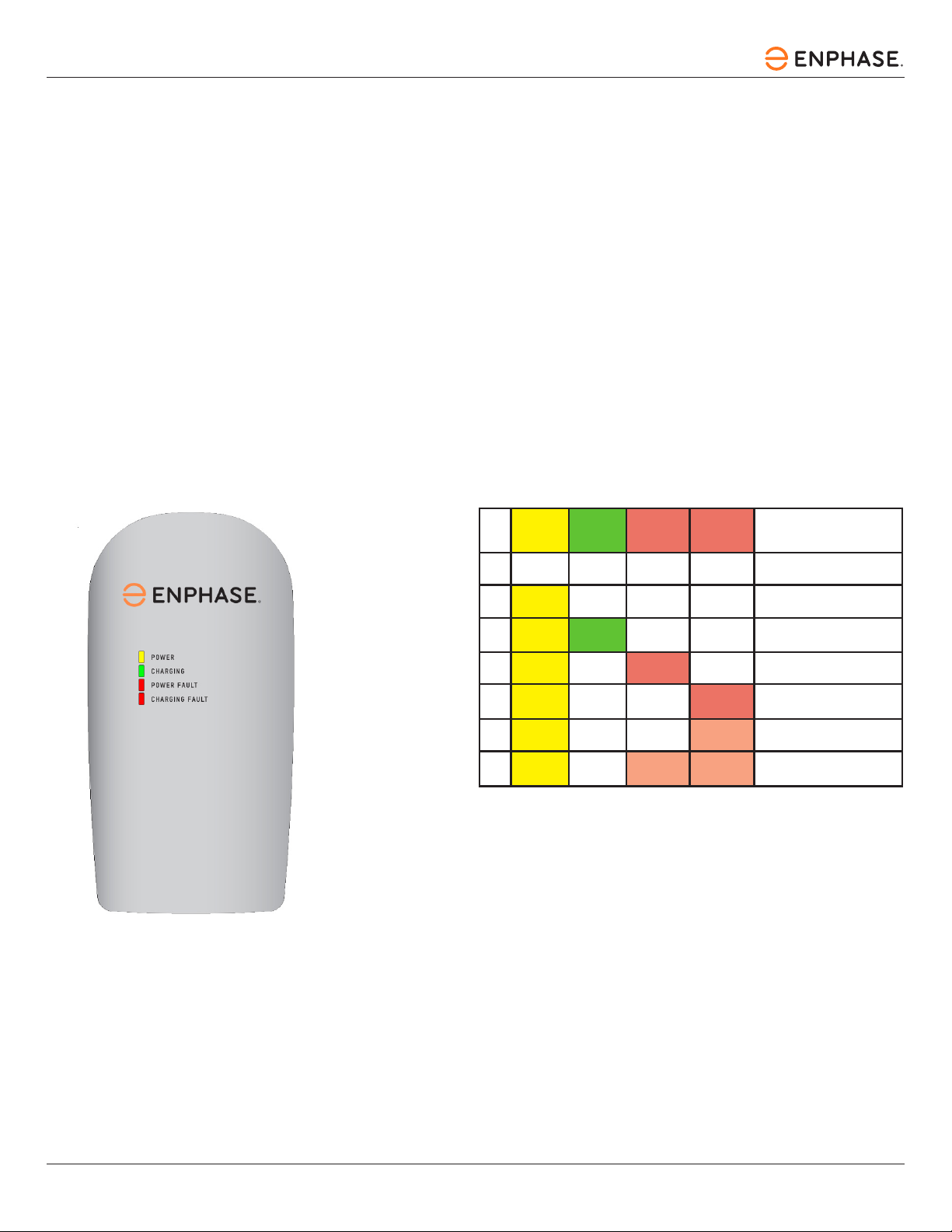
Front panel LED indications
The front panel on the HCS has four indicator lights, as shown in Figure 1.
Power (Amber) indicates that power is available on the EVSE.
Charging (Green) indicates that the vehicle is requesting a charge, and AC power is currently applied to the vehicle.
Power Fault (Red) indicates that the EVSE is not wired correctly. The problem can be due to improper grounding or a
missing Earth Ground. The wiring should be examined by a qualied electrician.
Charging Fault (Red) indicates that the EVSE is unable to communicate with the vehicle correctly, or a safety fault
condition has been detected by the unit.
Figure 1: HCS front panel
Table 1: Front panel LED information
NO POWER TO EVSE. CHECK
CIRCUIT BREAKER.
NOT PLUGGED INTO THE EV, OR
THE EV IS NOT READY TO CHARGE.
CHARGING ENABLED, POWER IS
APPLIED TO THE VEHICLE.
IMPROPER GROUNDING OR
GROUND IS NOT PRESENT.
PROBLEM WITH EV
COMMUNICATIONS.
DISCONNECT AND RESTART.
EV GROUND FAULT TRIP. CHECK
VEHICLE CONNECTION.
INTERNAL EVSE FAULT.
CALL FOR SERVICE.
1 OFF OFF OFF OFF
ON OFF OFF OFF
ON ON OFF OFF
ON OFF OFF
ON OFF OFF
ON OFF OFF BLINKING
ON OFF BLINKING BLINKING
ON - NOT
BLINKING
ON - NOT
BLINKING
AMBER
POWER
LED
GREEN
CHARGING
LED
RED
CHARGING
FAULT LED FAULT CONDITION
#RED
POWER
FAULT LED

© 2024 Enphase Energy Inc. All rights reserved. January 2024
1140-00277-03
12
HCS Installation and Operation Manual
Charging cable wrap guidelines
The HCS enclosure body is sculpted to allow the charging cable to be wrapped around it for convenient storage as well as to
keep the bulk of the cable o of the ground and out of the way. As the charge cable is comprised of a number of wires,
coiling the charge cable too tightly around the enclosure will result in the charge cable feeling warmer to the touch than
would ordinarily be the case.
To minimize this eect, it is recommended that the charge cable be loosely draped around the enclosure body with larger
loops. This will also permit greater convenience in “pulling o” additional loops if a longer charge cable reach is desired.
Figure 2: Drape the charging cable loosely around the enclosure
© 2024 Enphase Energy Inc. All rights reserved.
January 2024
140-00277-03
13
HCS Installation and Operation Manual
Installation - Service connections
CAUTION: To reduce the risk of re, connect only to a circuit provided with the appropriate maximum branch
circuit overcurrent protection in accordance with the National Electrical Code, ANSI/NFPA 70 (US), or the
Canadian Electric Code C22.1 (Canada).
Table 2: Service connections for HCS by model
HCS-40R HARDWIRED 40 A
HCS-40PR NEMA 6-50R 40 A/50 A
HCS-40PR NEMA 14-50R 40 A/50 A
HCS-50R HARDWIRED 50 A
HCS-50PR NEMA 6-50R 50 A
HCS-50PR NEMA 14-50R 50 A
HCS-60R HARDWIRED 60 A
HCS-80R HARDWIRED 80 A
HCS MODEL NO. CONNECTIONRECEPTACLE TYPE CIRCUIT BREAKER RATING

© 2024 Enphase Energy Inc. All rights reserved. January 2024
1140-00277-03
14
HCS Installation and Operation Manual
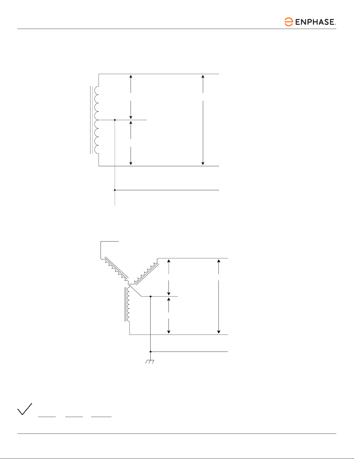
CAUTION: This is a single-phase device. Do not connect all three phases of a three-phase feed! You may use any
two phases of a three-phase wye-transformer feed. The center point of the three phases (usually used as Neutral)
must be grounded somewhere in the system. A Neutral connection is not required by the EVSE. Only Line 1, Line 2,
and Ground are required, as shown in Figure 3.
CAUTION: The two phases used must each measure 120 V to Neutral. Earth Ground must be connected to Neutral at
only one point, usually at the service entry breaker panel.
CAUTION: If a 240 V three-phase feed is from a Delta-connected secondary, the leg used must have a center-tap.
That tap must be Grounded. Only the two phases on either side of the center-tapped leg can be used. See Figure 4.
CAUTION: Warranty is void if this unit is not wired properly.
WARNING: Only a qualied electrician should perform the installation. The installation must be performed in
accordance with all local electrical codes and ordinances.
Only three wires are connected, but care must be taken that the service transformer secondary connection is denitely
known, and the three wires from the main circuit breaker panel are connected and labeled correctly. Figures 2, 3, and 4 show
the most common service transformer secondary wiring formats.
Notice that L1, L2, and Ground are labeled on each diagram. Those transformer outputs correspond to the same inputs
on the HCS. Also, each of the two three-phase diagrams shows an L3 output, which is not used. Do not connect all three
phases of a three-phase secondary to the EVSE. This is a single-phase device.
The Neutral at the service panel must be connected to Earth Ground somewhere in the system on any of the three
connection arrangements. Ground-fault protection is not possible unless the Neutral (center-tap on the service transformer)
is connected to an Earth Ground. If no Ground is provided by the electrical service, a grounding stake must be driven into
the Ground nearby, following local electrical codes. The grounding stake must be connected to the ground bar in the main
breaker panel and Neutral connected to the Ground at that point.
WARNING: Local electrical codes must always be followed when installing the grounding stake.
© 2024 Enphase Energy Inc. All rights reserved.
January 2024
140-00277-03
15
HCS Installation and Operation Manual
L1
L2
NEUTRAL
(NOT USED)
120 V
120 V
TERRE
240V
GROUND
Figure 3: 220 V/240 V single phase
The following diagrams illustrate the three service transformer secondary connections most
common in North America.
Figure 4: 208 V three-phase, wye-connected
L3 (NOT USED)
L2
L1
GROUND
NEUTRAL
(NOT USED)
120V 208V
120V
NOTE: With a wye-connected secondary, any two of the legs can be used to provide 208 V to the HCS. For example,
L1 & L2, or L1 & L3, or L2 & L3. Leave the unused leg open. Do not connect it to a Neutral bar or to Ground. Be sure
the center point is grounded to Earth somewhere in the system.

© 2024 Enphase Energy Inc. All rights reserved. January 2024
1140-00277-03
16
HCS Installation and Operation Manual
Figure 5: 240 V three-phase, delta-connected, with center-tap on one leg
CAUTION: With the delta connection, one leg must be center-tapped. Only the two phases on either side of the
center tap can be used. The two phases must both measure 120 V to Neutral. The third line (L3) of the delta is
208 V, with respect to Neutral, and is sometimes referred to as a “stinger”. Do not use this third line! Consult the
transformer manufacturer’s literature to be sure the single leg can supply the required power.
CAUTION: A three-phase delta-connected transformer secondary without a center-tap on one leg cannot be used
with the EVSE. No “Neutral” point is available to be connected to the ground for ground-fault protection. The EVSE
will not allow the contactor to close if it does not sense the presence of a Ground wire connected to a “Neutral”
point on the transformer secondary.
120 V
120 V
240 V
NEUTRAL
(NOT USED)
L1
L2
GROUND
L3 (DO NOT USE)
© 2024 Enphase Energy Inc. All rights reserved.
January 2024
140-00277-03
17
HCS Installation and Operation Manual
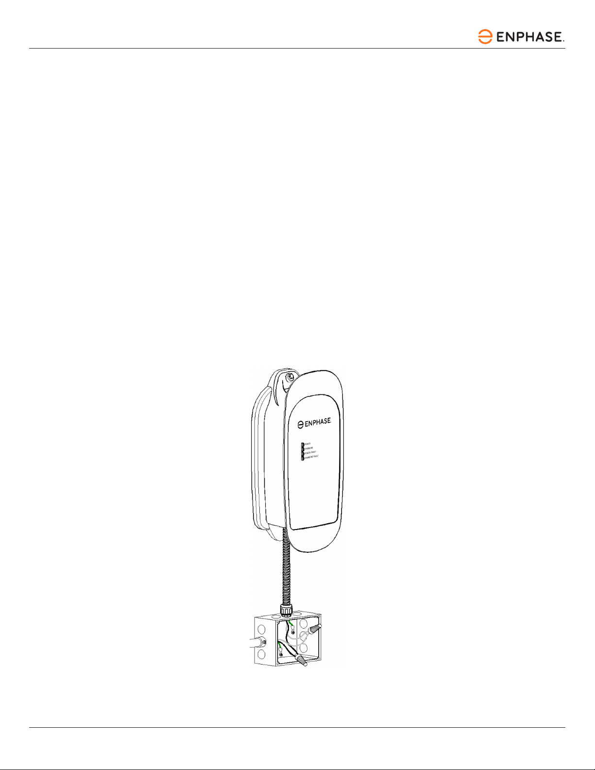
Wiring instructions (hardwired)
Route the HCS conduit to a nearby junction box. Use the included ½" trade size watertight conduit tting and sealing
washer to provide a moisture-resistant seal between the conduit tting and the junction box. If necessary, drill a ⅞" diameter
hole to accommodate the conduit tting. For outdoor installations, ensure the junction box is fully sealed using appropriate
electrical grade silicone sealant.
Before connecting the service conductors, please carefully read the section of this manual titled Installation - Service
connections. If unsure of the type of power provided at the service panel, please consult with the local utility or call a
Service Representative for assistance.
The three supplied HCS-40 service conductors use stranded 10 AWG 90°C copper wire.
The three supplied HCS-50, HCS-60, and HCS-80 service conductors use stranded 8 AWG, 90°C copper wire.
The insulation of each conductor is color-coded for standard 240 VAC installation:
Green: Ground
Black: Line 1 (120 VAC to Ground)
Red: Line 2 (120 VAC to Ground)
Figure 6:
Wiring the EVSE in a junction box

© 2024 Enphase Energy Inc. All rights reserved. January 2024
1140-00277-03
18
HCS Installation and Operation Manual
Receptacle instructions
(plug-in EVSE)
The plug-in HCS is tted with either a NEMA 14-50 or 6-50 plug extending from the bottom of the enclosure. The plug-in
EVSE must be mounted above the NEMA receptacle and must also be located within 12 in (305 mm) of it.
In both NEMA 14-50P and 6-50P congurations, the ground pin is located at the furthest point on the plug. It is
recommended that a NEMA 14-50R or 6-50R receptacle be oriented accordingly, such that the ground socket is at the
lowest point.
NOTE: For plug-type EVSEs, the provided 14-50R or 6-50R receptacle shall be installed by a qualied electrician
per local codes and standards and in accordance with the manufacturer’s instructions.
Figure 7: Preferred orientation of the NEMA receptacles below the plug-in EVSE

© 2024 Enphase Energy Inc. All rights reserved.
January 2024
140-00277-03
19
HCS Installation and Operation Manual
Receptacle safety instructions (240 V plug-type EVSE)
An EV Supply Equipment (EVSE) draws substantially more power than any average home load. For plug-type EVSE units,
the provided 14-50R or 6-50R receptacle shall be installed by a qualied electrician per local codes and standards and in
accordance with the manufacturer's instructions. If you require an additional or replacement receptacle, please contact
Enphase Support for assistance.
NOTE:
Installation of the receptacle shall be in accordance with local codes and the instructions provided with the
receptacle by a qualied electrician.
WARNING: Improper installation of receptacles may have an increased risk of overheating and may lead to re hazards.
It is also highly recommended that a qualied electrician inspects the premise wire connections on the back of a pre-existing
NEMA outlet before using it. Wire connection points behind the receptacle may become loose or oxidized if they were installed
many years ago and may cause the outlet to fail. Ensure that the receptacles are free of any physical damage or defects prior
to the installation of the EVSE.
If you believe the provided receptacle to be defective, please contact Enphase Support at 877-797-4743.
Figure 8: NEMA 6-50R/NEMA 14-50R
NEMA 6-50R NEMA 14-50R

© 2024 Enphase Energy Inc. All rights reserved. January 2024
1140-00277-03
20
HCS Installation and Operation Manual
Grounding instructions
This product must be grounded. If this product should malfunction, grounding provides a path of least resistance for electric
current to reduce the risk of electric shock.
Hardwired EVSE grounding
The hardwired HCS is equipped with three service conductors shielded by three feet of exible conduit. This product must be
connected to a grounded, metal, permanent wiring system, or an equipment-grounding conductor must be run with the circuit
conductors and connected to the ground lead on the product.
Plug-in EVSE grounding
The plug-in HCS is equipped with a supply cord having an equipment grounding conductor and a grounding plug. The plug
must be plugged into an appropriate receptacle that is properly installed and grounded in accordance with all local codes and
ordinances.
WARNING: Improper connection of the equipment grounding conductor may result in a risk of electric shock. Check
with a qualied electrician if doubt exists as to whether the product is properly grounded. Do not modify the plug
provided with the product – if it does not t the outlet, have a proper outlet installed by a qualied electrician.
Other manuals for HCS-40
1
This manual suits for next models
9
Table of contents
Languages:
Other enphase Automobile Batteries Charger manuals


