enphase HCS-D User manual

• • • • • • •
Model HCS-D
User Manual

HCS-D User Manual
2
To view the latest version of the product warranty, please visit
https://enphase.com/warranty/us
To view the latest version of this manual, please visit
https://enphase.com/installers/resources/documentation/
ev-chargers
© 2023 Enphase Energy. All rights reserved. Enphase, the e and CC logos, IQ, and cer-
tain other marks listed at https://enphase.com/trademark-usage-guidelines are trademarks
of Enphase Energy, Inc. in the US and other countries. Data subject to change.
Rev02/06-06-2023.
PLEASE NOTE
This user manual includes the latest information at the time of printing.
Enphase reserves the right to make changes to this product without
an authorized service facility may void the product warranty.
Contact a Customer Service Representative with any questions about
the use of this product. 877-797-4743
WARNING: This product can expose you to
chemicals, including Carbon Black, which is
known to the State of California to cause cancer.
For more information go to:

HCS-D User Manual
3
CONTENTS
IMPORTANT SAFETY INSTRUCTIONS........................................5
Instructions Pertaining to a Risk of Fire or Electric Shock 6
Additional Safety Information 8
FCC INFORMATION......................................................................9
OPERATION...................................................................................10
The HCS-D Front Panel 11
INSTALLATION - SERVICE CONNECTIONS.........................12
MOUNTING PROCEDURES .......................................................17
MOUNTING THE
CONNECTOR HOLSTERS......21
CHARGE CABLE WRAP GUIDELINES ...................................23
WIRING INSTRUCTIONS (Hardwired HCS-D) .......................24
RECEPTACLE INSTRUCTIONS (Plug-In HCS-D)..................25
RECEPTACLE INSTRUCTIONS (240V Plug Type EVSE)......26
GROUNDING INSTRUCTIONS..................................................27
HCS-D Hardwired EVSE Grounding 27
HCS-D Plug-In EVSE Grounding 27
USING THE PADLOCK................................................................28
MOVING & STORAGE INSTRUCTIONS.................................29
MAINTENANCE ...........................................................................30
CUSTOMER SUPPORT................................................................31
SPECIFICATIONS.........................................................................32

HCS-D User Manual
4
ILLUSTRATIONS
Figures
1. HCS-D Front Panel LED Information.......................................... 11
2. 220/240V Single Phase.................................................................14
....................................................14
4. 240V 3-Phase, Delta-Connected, w/Center-Tap on One Leg.......15
.......................................18
..........................................20
7. Mounting the SAE J1772 Connector Holsters Using the
.............................................38
8. Example of Installed HCS-D and Two Connector Holsters.........38
9.
Charge Cable Draped too Tightly Around the HCS-D Enclosure
....39
...........................................30
11. Preferred Orientation of the NEMA Receptacles Below
the Plug-in HCS-D .......................................................................32
12. Locking the SAE J1772 Connector with Padlock Included.........34
13. Charge Connector Secured with Padlock which Cannot
be Removed from Vehicle without Key.......................................34
14. Padlock Used in Combination with Connector Holster After .........
Charging .......................................................................................34
Tables
1. Front Panel Indicator Information................................................16
2. Service Connections for Standard and Ruggedized HCS-D ........17

HCS-D User Manual
5
IMPORTANT SAFETY INSTRUCTIONS
Carefully read these instructions and the charging instructions in
your vehicle owner’s handbook before charging your electric vehicle.
The following symbols may be found in this manual or on labels
NOTE:
This means pay particular attention. Notes contain
helpful suggestions.
CAUTION: This symbol means be careful. There is
potential to do something that may result in damage to the
equipment.
WARNING: This symbol means danger. You are in a
situation that could cause bodily injury. Before you work
on any electrical equipment, be aware of the hazards
involved with electrical circuitry and standard practices for
preventing accidents.

HCS-D User Manual
6
Instructions Pertaining to a Risk of Fire or Electric Shock
followed:
• Use this EVSE to charge electric vehicles equipped with an
SAE J1772 charge port only. Consult the vehicle’s owner
manual to determine if the vehicle is equipped with the
correct charge port.
• Make certain the EVSE SAE J1772 charge cable is
positioned so it will not be stepped on, tripped over, or
otherwise subjected to damage or stress.
• This product contains no user serviceable parts. Consult
the Customer Support section in this manual for service
information. Do not attempt to repair or service the EVSE
yourself.
• Do not operate your EVSE if it or the SAE J1772 charge
cable is physically open, cracked, frayed, or otherwise
visibly damaged. Contact a Service Representative for
service immediately. Consult the Customer Support
section in this manual for information on the Service
Representative in your area.
• Not for use in commercial garages where a
SAE J1772 charge cable.
• Do not allow children to operate this device. Adult
supervision is mandatory when children are in proximity to
an EVSE that is in use.

HCS-D User Manual
7
•
occasional
relocation, such as moving from one home to another home
.
•
prior to plugging in AND/OR unplugging 240V appliances
•
A high-quality industrial grade dedicated NEMA outlet
must be used with
your plug type EVSE.
• Do not use this EVSE with an extension cord or wall plug
recommend that plug-in EVSEs remain plugged into the
receptacle.
• Have an electrician
verify all wiring to the outlet is correct
and in compliance with local code requirements before
connecting the EVSE.
•
A worn or defective receptacle can cause the plug to overheat
during charge session to see if it is hot to touch. If so, we
recommend an electrician check the connection tightness and
replace the receptacle.
•
Ensure that the EVSE is mounted to the wall or placed on a
support so it does not hang from the
receptacle
.
Receptacle
s
are not designed to support the weight of the EVSE.
•
The EVSE shall be installed so that the power supply cord

HCS-D User Manual
8
Additional Safety Instructions
WARNING:
breaker panel before moving, servicing or cleaning the unit.
WARNING:
at the circuit breaker panel prior to plugging into or
unplugging from a wall socket.
NOTE: VENTILATION - Some electric vehicles require
an external ventilation system to prevent the accumulation
of hazardous or explosive gases when charging indoors.
Consult the vehicle owner’s manual to determine if your
vehicle requires ventilation during indoor charging.
NOTE: Vehicles which conform to the SAE J1772
standard for communication can inform the charge
station that they require an exhaust fan. The HCS is not
equipped to control ventilation fans. Do not charge the
vehicle with the HCS if ventilation is required.
CAUTION: DO NOT CHARGE a vehicle indoors if it
requires ventilation. Contact a Service Representative for
information.
Save these instructions for future reference.

HCS-D User Manual
9
FCC INFORMATION
This device complies with Part 15 of the FCC rules. Operation
any interference received, including interference that may cause
undesired operation.
This product has been designed to protect against Radio Frequency
operation.
If interference to the EVSE is suspected, the following steps
should be taken before consulting a Enphase Sales or Service
Representative for assistance:
1. Reorient or relocate nearby electrical appliances or
equipment during charging.
during charging.
CAUTION
by other than an authorized service facility may void
FCC compliance.

HCS-D User Manual
10
OPERATION
NOTE:
discussed in this manual; we recommend contacting
Enphase, Inc., as some units are not yet available.
The HCS-D EVSE is a compact wall or pedestal-mounted EVSE
that provides the Plug-in Hybrid or Battery Electric Vehicle
manageable link between the power grid and the PEV.
Simply unwrap the SAE J1772 charge cable and plug the connector
the EVSE makes 100% of its power available to that vehicle.
vehicle completes its charge, the other vehicle has access to 100%
of the power until it completes charging, is unplugged, or another
vehicle that requests power is connected to the HCS-D. The status
of each connected vehicle is displayed on the front panel of the
HCS-D.
Normally, the vehicle will immediately request a charge once the
charging cycle will begin. After an average driving day the vehicle
battery pack will require several hours to recharge completely.
Charging overnight is the most convenient way to maintain healthy
batteries and ensure the vehicle’s full range will be available for
the next day.
press and hold down the latch release lever on the connector
unplug the connector from the vehicle charge port.

HCS-D User Manual
11
The HCS-D Front Panel
The front panel on the HCS-D has six
indicator lights, as shown in Figure 1.
The three colored indicators - left and
right - display status for each of the
two vehicle connectors.
POWER
power is available to the HCS-D.
FAULT
Conditions in Table 1.
CHARGING
the vehicle is requesting a charge and
AC power is currently applied to the
vehicle.
Figure 1: HCS-D Front
Panel LED Information
Table 1: Front Panel Indicator Information
ON - not
blinking
ON - not
blinking
No power to the EVSE. Check circuit breaker.
EVSE has power, not plugged into PEV, or
PEV not requesting a charge.
Charging enabled, power is applied to the
vehicle.
Ground monitor trip, improper grounding or
ground is not present.
PEV Pilot communication out of spec,
disconnect from vehicle and reconnect.
PEV ground fault trip. Check vehicle
connection, disconnect and restart.
Internal EVSE Fault. Disconnect from vehicle, turn power
off and then back on. If fault persists, call for service.
Internal EVSE Fault. Disconnect from vehicle, turn power
off and then back on. If fault persists, call for service.
Internal EVSE Fault. Disconnect from vehicle, turn power
off and then back on. If fault persists, call for service.
Internal EVSE Fault. Disconnect from vehicle, turn power
off and then back on. If fault persists, call for service.
Amber
POWER Red
FAULT Fault Condition
#Green
CHARGING
2 ON
3 ON ON
4 ON
1 - blink
2 - blinks
3 - blinks
4 - blinks
5 - blinks

HCS-D User Manual
12
INSTALLATION - SERVICE CONNECTIONS
CAUTION:
circuit provided with the appropriate maximum branch
circuit overcurrent protection in accordance with the
HCS-D40R (Hardwired) 40A n/a
HCS-D40PR NEMA 14-50P 40A/50A NEMA 14-50R
HCS-D50R (Hardwired) 50A n/a
HCS-D50PR NEMA 14-50P 50A NEMA 14-50R
HCS-D Model Circuit Breaker Rating Receptacle Type
Table 2: Service Connections for Standard and Ruggedized
HCS-D
CAUTION: This is a single-phase device. Do not connect
all three phases of a 3-phase feed! You may use any two
phases of a three phase wye-transformer feed. The
must be grounded somewhere in the system. A Neutral
connection is not required by the HCS-D. Only Line 1, Line
2, and Ground are required, as shown in Figure 3.
CAUTION: The two phases used must each measure 120V
to Neutral. Earth Ground must be connected to Neutral at
only one point, usually at the service entry breaker panel.
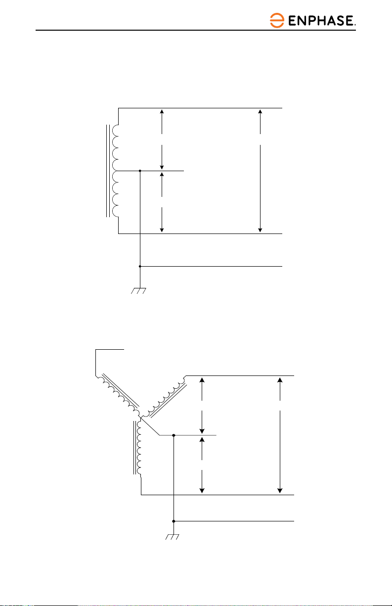
CAUTION: If a 240V 3-phase feed is from a Delta-
connected secondary, the leg used must have a center-tap.
That tap must be Grounded. Only the two phases on either
side of the center-tapped leg can be used. See Figure 4.
CAUTION: Warranty is void if this unit is not wired
properly.

HCS-D User Manual
13
WARNING
the installation. The installation must be performed in
accordance with all local electrical codes and ordinances.
Only 3 wires are connected, but care must be taken that the service
transformer secondary connection is known, and the
3 wires from the main circuit breaker panel are connected and
labeled correctly. Figures 2, 3, and 4show the most common
service transformer secondary wiring formats.
Notice that L1, L2, & Ground are labeled on each diagram. Those
transformer outputs correspond to the same inputs on the HCS-D.
Also, each of the two 3-phase diagrams shows an L3 output, which
is not used. Do not connect all three phases of a 3-phase secondary
to the HCS-D. This is a single-phase device.
The Neutral at the service panel must be connected to Earth
Ground somewhere in the system on any of the three connection
arrangements. Ground-fault protection is not possible unless the
Earth Ground. If no Ground is provided by the electrical service, a
grounding stake must be driven into the Ground nearby, following
local electrical codes. The grounding stake must be connected to
the ground bar in the main breaker panel, and Neutral connected to
Ground at that point.
WARNING: Local electrical codes must always be
followed when installing the grounding stake.
The following diagrams illustrate the three service transformer
secondary connections most common in North America.
HCS-D User Manual
14
Figure 3: 208V 3-Phase, Wye-Connected
L3 (NOT USED)
L2
L1
GROUND
NEUTRAL
(NOT USED)
120V208V
120V
L1
L2
NEUTRAL
120V
120V
GROUND
(NOT USED)
240V
Figure 2: 220/240V Single Phase

HCS-D User Manual
15
Figure 4: 240V 3-Phase, Delta-Connected, w/Center-Tap on
One Leg
120V
120V
240V
NEUTRAL
(NOT USED)
L1
L2
GROUND
L3 (DO NOT USE!)
NOTE:
the legs can be used to provide 208V to the HCS-D. For
example, L1 & L2, or L1 & L3, or L2 & L3. Leave the
unused leg open. Do not connect it to a Neutral bar, or
to Ground. Be sure the center point is grounded to Earth
somewhere in the system.
CAUTION: must be
center-tapped. Only the two phases on either side of the
center tap can be used. The two phases must both measure
with respect to Neutral, and is sometimes referred to
Do not use this third line! Consult the
transformer manufacturer’s literature to be sure the single
leg can supply the required power.

HCS-D User Manual
16
CAUTION: A 3-phase delta-connected transformer
secondary without a center-tap on one leg cannot be
used with the HCS-D
be connected to ground for ground-fault protection. The
HCS-D will not allow the contactor to close if it does
not sense the presence of a Ground wire connected to a

HCS-D User Manual
17
MOUNTING PROCEDURES
Locate the wall mounting location for the EVSE:
• On the hardwired HCS-D, the three service conductors are
unit. The HCS-D must be positioned such that this conduit
can reach a nearby junction box.
• On the plug-in HCS-D, the NEMA plug head is connected
bottom side of the HCS-D. The plug-in HCS-D must be
positioned such that this plug can safely be inserted into a
wall-mounted NEMA socket. Do not allow the power supply
• Position the bottom of the EVSE at a comfortable height and
front panel indicators of the EVSE can clearly be seen by
the user of the device.
• The HCS-D has two vertically aligned mounting holes
Use a ruler or template to mark hole locations on the
mounting surface.
WARNING:
EVSE at the circuit breaker panel prior to plugging it in or
breaker prior to unplugging it or disconnecting the unit from
the service lines.

HCS-D User Manual
18
HCS-D EVSE Mounting for Hollow-Wall Construction
• Place the unit such that both mounting holes can take
advantage of solid structural framing inside of the wall or a
strong wall surface such as plywood.
•
HCS-D to a wooden structure. Pre-drill appropriately sized
pilot holes to allow the lag screw to grip the wooden structure
while preventing the wood from cracking or splintering while
the screw is fastened.
• The included plastic angle washers can be oriented to allow
the lag screws to be fastened at an angle while still providing a
•
plastic angle washer and the head of the lag screw.
• If either mounting hole does not have a solid mounting
necessary to use proper anchoring hardware such as drywall
toggles or molly bolts.
Figure 5: Mounting the HCS-D to a Hollow-Wall
Note Diagonal Mount
Washer is marked with
an “O” shape
Longer
Shorter
Diagonal
Screw Mount Perpendicular
Screw Mount
”

HCS-D User Manual
19
HCS-D EVSE Mounting for Solid-Wall Construction
• To secure the unit in concrete, pre-drill appropriately sized
holes and use multi-set or wedge anchor hardware at both
mounting points.
• To secure the unit in brick or stone, pre-drill appropriately
sized holes and use sleeve anchors at both mounting points.
• The included plastic angle washers can be oriented to allow
bolts to be fastened either at an angle or perpendicular to
the mounting surface. NOTE
plastic angle washers included. Select those washers that best
orient them accordingly.
•
• NOTE that if the head of the mounting hardware is smaller
washer will need to be placed between the plastic angle washer
and the mounting hardware.
•
recommended. The HCS-D plastic angle washer hole size is
Place appropriately sized washers between the screw heads and

HCS-D User Manual
20
Figure 6: Mounting the HCS-D to a Solid-Wall
Longer
This manual suits for next models
1
Table of contents
Languages:
Other enphase Automobile Batteries Charger manuals


