HYPERVOLT Home 3.0 User manual

Home 3.0
Quick
Start
Guide
IMPORTANT - PLEASE READ
This is a basic guide, it must not be used as a
substitute for the full manual which should be
consulted before installation.
This Guide MUST be handed to the end user.

Overview Internal Layout Overview Key Components
32
1
2
6
7
9
3
5
11
13
4
12
8
10
1Incoming Supply Connections - LIVE, NEUTRAL & CPC (Earth)
We recommended using stranded cables with ferrules. Tighten to 2 Nm.
2Tethered Cable Connections - This is where the tethered car charging cable is
connected. If you replace this cable remember to put the Blue & Brown wires back
through part , not the Green & Yellow.
3CP Connection - This is where the control pilot from the car charging cable is
connected. It goes in the right side, push the tab to insert.
4CT Connection - The CT clamp supplied should be connected here, extend the
cable as necessary using HyperConnect or CAT cable. Use the Left plug for ALM, The
Right Plug is for Additional monitoring (see main manual).
5RJ45 Connection - For a hardwired internet connection plug in here. You only need
to use the Orange & Green pairs of a CAT cable in the standard T-568B conguration.
7Derating DIP Switches - For hard setting the Maximum charging limit (See page 6).
Soft set in the App. (Factory set to 32A)
8Sensing Device (RCD-DD) - Internal 6mA DC sensor. You must t an external AC
Sensing “A” Type RCD.
10 Cut for Rear Entry Gland - Drill out if required, 25mm Max Ø, seal accordingly.
Original entry hole must be sealed if this one is used.
6ALM Adjustment Dial - For setting the Automatic Load Management. (See page 6).
9LED Front Plate Connection - This is where the LED lights plug in.
11 Additional Cable Entry - Drill out for Band 1 Cables, 20mm Max Ø.
12 Main Brain - Where all the HyperMagic happens.
13 HyperConnect Cable - Live, Neutral & CPC + CAT 5 (4mm or 6mm).
Available directly from Hypervolt.
8

4 5
Installation Electrical Safety
Your Hypervolt comes with built-in safety protection. It is imperative
to understand and include the additional external safety protection all
electric vehicle charging points require.
Hypervolt installations must only be done by quali ed, registered
electricians. All installation work for safety & preservation of warranty
must be compliant with BS7671 as amended.
External Equipment Required
Residual Current Device
The Hypervolt Home 3.0 shall be protected by an external RCD device. This should
as a minimum be an Individual Type “A” Double Pole Device. Only one external
RCD should be inline and never a Type “AC” .
Overcurrent Protection
The Hypervolt Home 3.0 shall have external overcurrent protection no greater than
40A. This can be in the form of an RCBO or if using a separate RCD this can be an
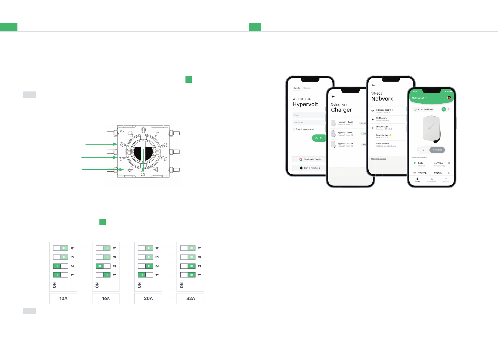
MCB. We recommend using a 40A device when the Hypervolt is used on it’s
maximum output setting (factory set)
Surge Protection Device (SPD)
We recommend that all Hypervolt’s shall be protected by an external SPD to prevent
transient overvoltages causing the built-in safety services to fail.
Consideration dependant on external factors should be given as to if a Type 1 or
Type 2 device would be more suitable.
Built In
PEN Fault Protection
The Hypervolt Home 3.0 comes with built in PEN fault protection for additional
safety, should a fault occur with the electrical distributors network. It eliminates the
need to install an earth rod.
Residual DC Device
The Hypervolt Home 3.0 has a built in DC RCD-DD ( ) that can protect against DC
fault currents over 6mA.
8
Installation Connect the supply
Connection to an Electrical Supply (230V)
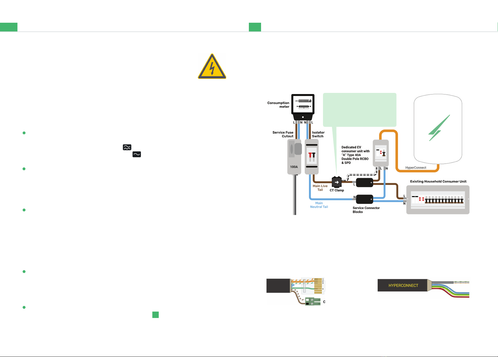
HyperConnect
Below is the most commonly used & recommended method of connecting your
Hypervolt to an electrical supply.
We recommend using HyperConnect cable for installing Hypervolt EV Chargers, it
contains power, data and CT connection wires in one neat easy to t cable.
We do not recommend the use of NYY-J Cable.
4 & 6mm Non & SWA Live, Neutral,
CPC & Cat 5e
The White Wire from the CT goes in the Left &
Black in the right. Extend as necessary, a Brown
pair of a CAT cable is used in this example.
CT Plug
RJ45 Plug
(T-568B)
CT Plug
The CT clamp must be installed
to measure the total supply load
with the arrow pointing in the
direction of current fl ow.

7
Using the Charger Connecting Online
To adopt your Hypervolt charger to an App account and get it online, rst download
the Hypervolt App (QR Code on back page) then follow these 4 steps:
Sign Up / Sign In To start you will need to create a Hypervolt user account via the
‘Sign Up’ tab and then use the ‘Sign In’ tab to login.
1.
Adopt Next you need to ‘adopt’ your charger by choosing an ‘Available’ Hypervolt on
the ‘Select your charger’ page.
2.
Connect to your Wi-Fi Next select your Wi-Fi connection and enter the
password.
3.
Success ! Once your Hypervolt has connected the pulsing white ring around the
edge of the cover will turn solid blue. You can now use the App with all its great
features.
4.
Hypervolt Trusted Installers have access to an Installers App for this process.
6
Installation Setting ALM and Current
Adjust the ALM
Hard setting the current limit
The ALM (Automated load management) is used to provide protection to the incoming
supply by preventing charging above 6A at an upper limit set by dial ( ).
The hard current limit sets the maximum current the Hypervolt will charge a
vehicle at. Set the dip switches ( ) accordingly. The switches come factory set
to 32A (All ‘off ’ to the right).
The dial is small so double check you have set it correctly, The arrow in the picture below
shows where the dial is pointing, 5 in this case.
Note:
The current limit can be soft set in the App, a hard set overrides a soft set.
6
8: 100A
7: 80A
6: 60A
7
Note:

Installation LED Statuses
* If your Hypervolt is continually displaying a red fault status please contact our support team.
The LED coloured light status show what action your charger is performing. After your Hypervolt charger has been installed and setup, below are the diff erent
charging options that you can choose to suit your needs and get you started:
If you have selected an LED Mode or dimmed to 0% the status colour will show briefl y before
returning to 0% or the mode colours.
Your Hypervolt comes with a pre-set
default schedule (23:00 - 06:00). On the
App Home page tap on
to swap to Plug and Charge mode.
If you have solar panels change the
charging mode to best suit your needs.
Standby
Plug & Charge
Not Online
(Pulsing White Ring with
Solid Blue Bolt)
Paused (Pulsing)
Stopped (Flashing)
Delayed Start
(Random Start On)
Charging Standby
Schedule Charge
Waiting to
Schedule Charge
LockedWaiting for Solar
(Super Eco Mode)
Unauthorised Use
(Flashing)
*Fault
Using the Charger How to charge
98
Plug and Charge
Scheduled Charging
Simply plug the charging cable into
your EV. When you want to stop
charging tell your car to unlock the
cable then unplug.
You may want to only charge at
speci c times, maybe to take
advantage of cheaper electricity
tariff s.
You can do this using the ‘schedule
charge’ activation mode.
Edit the schedule to match your
prefered charging times and tap
save. Your Hypervolt will turn purple.
Now when you plug your EV in it will
only charge within your set times.
App Home page tap on
Note:
Note:

10
Smart Charging Regulations What you need to know
Default Schedule
Random Start
The latest UK ‘Electric Vehicle Smart Charge Points Regulations’ (No. 1467) help to
manage the increased electrical demand as more people move to the advantages of
electric transportation. In line with these regulations the Hypervolt comes out of the
box with two default settings.
Here’s what you need to know:
Your Hypervolt will come with a pre set off peak
schedule to encourage charging during lower
demand times (23:00 - 06:00).
You can opt out by either changing the schedule,
choosing Plug and Charge or unselecting “Default
Schedule” on the ‘Your Hypervolt’ page.
Your Hypervolt will come pre set to random start every
time a charging session begins in Boost Mode, whether
that be from a Schedule or a straight Plug and Charge.
The charge will be delayed anytime up to 10 minutes.
The charging indicator will show as “Waiting” with a delay
countdown above.
You can opt out of this by unselecting it on the ‘Your
Hypervolt’ page.
11
Smart Charging Regulations What you need to know
How cyber secure is my device?
How long will your Hypervolt device be supported for?
How to delete your
personal data from
the device
The Hypervolt Home 3.0 uses state of the art encryption both on the device and
embedded in our software, resulting in a very cyber secure product. There are no
additional steps you need to take to ensure your device is secure apart from the
standard actions such as not sharing your Hypervolt account login details.
Hypervolt will issue updates to your Home 3.0 for a minimum of 3 years from the
date of purchase.
Whilst a Hypervolt Home
3.0 does not store personal
details about yourself, it does
store information about how
you use your charger, wi
credentials and other
information that the charger
needs to support its features
and maintain functionality.
You can delete any data
stored on your charge point
by going into your app then
settings -> ‘Wipe Device Data’.

12
Need more support?
Your installer must register the installation to start the Hypervolt warranty.
Contact us
Go to hypervolt.co.uk/support for
lots of additional support materials.
Hypervolt Home 3.0 Quickstart guide Version 2.0. Please note this Quick Start guide is subject to change.
0333 090 3093
support@hypervolt.co.uk
www.hypervolt.co.uk
30 Churchill Pl, London E14 5RE,
United Kingdom
Your Hypervolt’s details
Register
Scan me to register
your Hypervolt and
start your warranty
App
Want to Control your
charger with the app,
Scan me.
Full Manual
Scan me to Download
the Full Manual
Other manuals for Home 3.0
3
Table of contents
Other HYPERVOLT Automobile Batteries Charger manuals