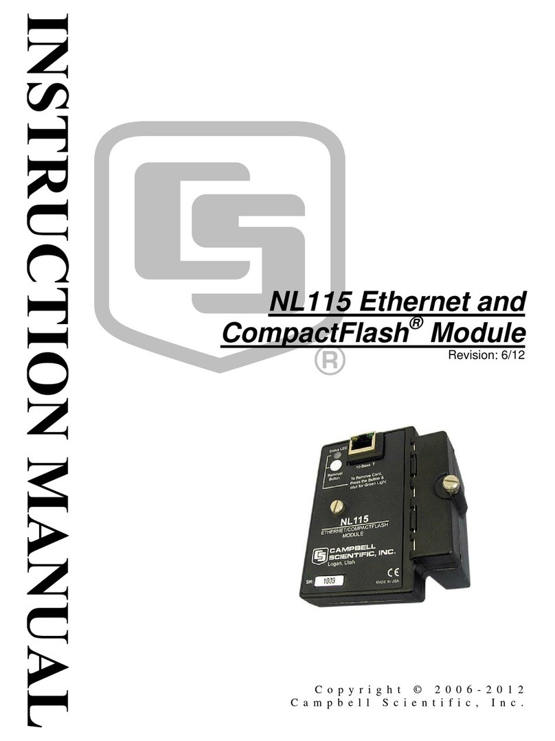
Ensemble Designs Avenue Express Control Panel Instruction manual

Avenue™
Express Control
Panel
Data Pack
Revision 2.0 SW 2.2.0
Express Panel-1
INTRODUCTION
This data pack provides detailed installation, configuration and operation information for
the Avenue Express Control Panel as part of the Avenue Signal Control System.
The module information in this data pack is organized into the following sections:
• Express Control Panel Overview
• Express Control Panel Application
• Express Control Panel Installation
• Express Panel Controls Overview
•Express Panel Configuration
• Channel Select Configuration and Operation
• Warranty and Factory Service

Avenue Express Control Panel
EXPRESS CONTROL PANEL OVERVIEW
The Avenue Express Control Panel is excellent for use in satellite receiving, ingest areas,
and remote trucks. The Avenue Express Control Panel has the following overall features:
•Elegant control for the 7500, 8400, and 8500 Video Processing Frame Sync
modules as well as other Avenue modules
• Dedicated knobs for video, chroma, pedestal, and hue
• Adjust audio levels for multiple groups
•Control all parameters of all Avenue modules
• Easily adjust video levels, timing, audio delay and other parameters
• Intuitive user interface
•Compact 1 RU design
•Easy to install
• User Levels for security
•Module lock out for critical paths
•Use any combination of Touch Screen, Express Panels or PCs for control and
monitoring
While it can be used to control any Avenue module, the Express Panel really shines when
used with the Signal Acquisition system, the 7500, 8400, and 8500 Video Processing
Frame Sync modules.With dedicated video, chroma, pedestal, and hue knobs, live shading
is easy. The continuous rotation velocity sensitive knobs are responsive and dependable.
Audio levels for multiple groups are easily accessed as well. All other parameters,
including timing and audio delay, are accessed through an intuitive menu interface.
One Express Panel can control most modules in your Avenue system. Refer to the manual
data pack for particular modules that cannot be controlled by the Express Panel.
Alternately you can have as many Touch Screen and Express Panels as you like in your
Avenue system. Customize the control system for your needs. Any number of 1 RU and 3
RU Avenue frames can be connected together through the AveNet interframe LAN bus to
create an Avenue network. These networks can then communicate over Ethernet using
the AveNet over IP feature (AVIP). The frames can be controlled by a single control panel
or any number of control panels installed on the network.
Remote control of Avenue frames is provided through a series of menus for system config-
uration and for setting parameters for each module installed in the frames. A series of
menus allow you to set AveNet and IP Addresses, enable AveNet Over IP (AVIP), name
and monitor modules, frames and groups of frames, and set module parameters in the
system.
To configure and use the Express Panel, follow the instruction starting with Express
Panel Configuration.
Express Panel-2
Avenue Express Control Panel

Avenue Express Control Panel
Express Panel-3
EXPRESS CONTROL PANEL APPLICATION
In the illustration below, an Avenue Express Control Panel is used in a satellite receiving
area and interfaced to a complete Avenue system via AveNet. Any number of frames,
Touch Screens, and Tabletop or Express Control panels can be connected via AveNet using
twisted pair cable. PCs connect to any frame serially or via Ethernet.
Avenue Express Control Panel Application

Avenue Express Control Panel
Warning
Rick of electric shock. Qualifed service personael should only access
power supply after frame has been unplugged from power.
EXPRESS CONTROL PANEL INSTALLATION
The 1 RU Avenue Express Control Panel is designed to be installed in a standard 19 inch
rack with four customer-supplied standard rack screws. This section explains any physical
installation and cabling instructions necessary for using Avenue Express Control Panels.
After physical installation, network configuration of the Express Panel and System
parameter such as LED brightness can be set up using the Local controls in the Express
Panel menus. Refer to the Configuration section of this data pack.
Cabling
Network connection of an Express Panel is made on the rear of the panel as illustrated
below. The Express Panel can Avenue frames through via Ethernet, through an AveNet
connection, or with a serial interface.
AveNet:
AveNet is the Avenue control bus that allows communication between frames by the
System Control modules in each frame. Up to 20 frames can be connected on each
individual AveNet network. Any number of AveNet networks can then be connected
together via Ethernet. AveNet connection between frames requires looping between
Express Panel–4
Express Control Panel Rear Connectors
AveNet RJ11 Connector Pinout

Express Panel–5
the standard RJ11 LAN connectors of each frame with standard phone cable or
custom-made simple twisted pair LAN cable. The unused connectors must be
terminated with 100 ohm LAN terminations at the first and last frames in the group.
Pinouts of the RJ11 connector and termination are shown below.
Each Avenue device on the AveNet LAN network must have a different AveNet
address. The address is set using the Status menu functions on the front of the
5030/35 Control module in each frame. Refer to the Express Panel Networking
section for detailed information.
Avenue Express Control Panel
Serial Connector Pinout

System Overview–6
EXPRESS PANEL CONTROLS OVERVIEW
The Express Control Panel is divided into two main control areas: the Channel controls
and the Configuration controls.
Channel Controls
The Channel controls on the Express Panel are shown in the figure below. The 10 Channel
Select pushbuttons, the Video and Audio pushbuttons, and the read-out display on the left
side of the panel are the main Channel controls.
AChannel is defined as a set of video and audio processing control parameters from any
Avenue module connected to the Express Panel. The video and audio can be from different
modules if desired. Video and audio parameters are configured to a Channel Select
pushbutton with the Configuration controls as described in detail later in the Channel
Configuration section of this data pack. When a configured Channel is recalled by
selecting a Channel Select pushbutton, each proc amp parameter or audio level can be
changed using the four knobs under the display.
Channel Control Overview on Express Panel
Channel Select pushbuttons
Audio pushbutton for
saving/recalling audio
parameters assigned to
highlighted Channel
Select pushbutton.
Parameter display
window.
Parameter control knobs
for adjusting Video and
Audio proc controls
assigned to highlighted
Channel Select
Video pushbutton for
saving/recalling video
parameters assigned to
highlighted Channel
Select pushbutton.
Avenue Express Control Panel

Ethernet:
Avenue frames may be controlled by a Express Panel connected to a 10BaseT
Ethernet network. The IP Address for each frame in the network is set on the System
Control module in each frame or frames connected to the Ethernet network. The
Avenue backplanes have a standard RJ45 connector for Ethernet interface.
Each Avenue device on the Ethernet network must have a different IP Address,
including the Express Panel. The address for the frame is set using the Status menu
functions on the front of the 5030/35 Control Module in each frame or a Touch Screen
or Express Panel. Refer to the Express Panel Networking section for detailed
information.
Serial Control:
If using a serial interface connection from the Express Panel to remotely control a
frame (or series of frames connected via AveNet), connect a 9-pin D to 9-pin D cable
(pinout is shown in the pinout diagram below) from the Serial Control port on the
rear of the Express Panel to the serial port on an Avenue frame with a 5030/5035
Control module installed.
Power:
Connect the AC power adapter included with the panel to the power connection on the
Avenue Express Control Panel
Express Panel–7
Configuration Control Overview on Express Panel
Configuration Display
Control Knob for changing
values in the configuration
display and also for moving
in and out of configuration
menus when pushed in.
Select Config pushbutton
to enable configuration
User Level pushbutton
(not active)
Load/Save pushbutton
for defining channels.
Menu Select arrow
pushbuttons to move in
and out of configuration
menu levels.
CLR (Default) pushbutton
to return Channel parame-
ters to defaults.

far right of the rear panel. Tighten the protective cap to hold the power connection in
place. As soon as power is connected, the panel will be powered up. After reviewing
the control overview next, proceed to the Express Panel Configuration section.
Avenue Express Control Panel
Express Panel–8

Configuration Controls
The main configuration controls present on the Express Panel are shown in the figure
below. These controls and the read-out display on the right side of the panel are used to
configure the panel itself, configure frames on the panel network, modules in the frames,
and the 10 available channels on the left side of the panel.
Operation of each of these controls is described in more detail in each configuration
section (Express Panel, Frames, Modules, and Channels).
Avenue Express Control Panel
Express Panel–9
Express Panel Networking Menu Tree

Avenue Express Control Panel
Express Panel–10
EXPRESS PANEL CONFIGURATION
Express Panel configuration is done as described in the following steps:
• Express Panel Networking
• Express Panel System Configuration
Express Panel Networking
The first step in Express Panel configuration is to connect the Express Panel to an
Avenue network. The panel can communicate through an Ethernet or AveNet connection
to an existing Avenue network or be the central controller of a separate network. Please
refer to the Avenue System Overview that accompanies every Avenue frame for complete
details on interfacing Avenue control devices to a network. There are a number of ways to
configure the panel in a network.
Begin Express Panel network configuration by entering the Configuration mode. Use the
instructions below and refer to the graphical representation of the menu tree given on the
following page.
1. Enter the Configuration mode by selecting the Select Config pushbutton. It will
illuminate red to indicate you are now in Configuration mode.
2. The first configuration menu to come up in the Configuration display will be the
Choose Frame by Knob. If no networking parameters are set up for the panel,
only ajLocal frame will be listed (this panel).
3. Enter the jLocal mode by selecting the Right Arrow pushbutton or push in the
Configuration knob.
4. The jLocal mode has three choices: Network,Channels (not active), or System.
Use the Configuration knob to place the indicator carat next to the Network
selection and enter the mode by selecting the Right Arrow pushbutton or push in
the Configuration knob.
5. The Network mode will have the following network parameters that can be set for
this panel depending on how it is being interfaced into an Avenue network. (This is
explained in more detail in the Avenue System Overview Networking section as
mentioned earlier.)
• Panel Name
• Panel Group
• AveNet Address
• IP Address
• AVIP Enable
6. Use the Configuration knob to move the indicator carat to each of the selections,
then enter each selection by selecting the Right Arrow pushbutton or push in the
Configuration knob.
7. For each panel networking parameter, use the Left and Right Arrow pushbut-
tons to scroll to each letter or number in the parameter. For example, to assign a
panel name, use the Right Arrow pushbutton to scroll to the first letter in the
default panel name. To change this letter, rotate the Configuration knob until you
reach

the desired letter. Move to the next letter with the Right Arrow pushbutton and
use the Configuration knob to select the second letter of the name.
8. Once you have finished assigning a panel name, use the Left Arrow pushbutton
to leave this menu and return to the main Network menu. Use the Configuration
knob to put the indicator carat on the next parameter you wish to set.
After setting a parameter, you must exit the menu back to the last main menu
then use the Configuration knob to move to the next selection.
9. Continue to assign parameters in the list as required. Exit out of the Network
menu to the System menu. Note that the Channels selection is not active at this
time.
Avenue Express Control Panel
Express Panel–11
Express Panel System Parameters Menu Tree

Express Panel System Parameters Configuration
The next step in Express Panel configuration is to configure the System parameters for
the panel. This includes LED brightness, LCD contrast and other panel characteristics.
Read-only status information and System Reset controls are also available from this
menu.
Continue the configuration by moving the indicator carat to the System selection and
enter this menu. Use the instructions below and refer to the graphical representation of
the System menu tree given on the following page.
1. The System menu will have the following parameters that can be set for this
panel to determine panel characteristics as follows:
•LED Brightness
•LCD Contrast
• Software Version
•Reset EEProm
•System Reset
•Panel Test
2. Use the Configuration knob to move the indicator carat to each of the selections,
then enter each selection by selecting the Right Arrow pushbutton or push in the
Configuration knob.
3. For panel system parameters requiring a value such as LED Brightness and LCD
Contrast, use the Configuration knob to scroll through the values to reach the
value desired.
4. The Software Version is a read-only field describing the software version running
on this panel.
5. The Reset EEProm and Reset System are activated by pushing in the
Configuration knob.
6. A Panel Test is included which will report the name of the control as you activate
it. Each knob, pushbutton and LED can be tested and will be reported on the
display. The following panel controls will be reported when activated:
•Left and Right arrow pushbuttons
• Knobs 1-4 and Knob 5 (Configuration)
• Clear, Save, and User pushbuttons
•Channel pushbuttons 1-10
Avenue Express Control Panel
Express Panel–12

Avenue Express Control Panel
System Overview–13
Frame Parameters Menu Tree

Frame and Module Control and Configuration
Now that the Express Panel is set up in the Avenue network and configured for use in
your environment, you can access frames on the network and individual modules in each
frame and use the panel for the controls described in this section.
Frame Control and Configuration
To access the available frames on the Avenue network, follow the steps below.
1. Enter the Configuration mode by selecting the Select Config pushbutton. It will
illuminate red to indicate you are now in Configuration mode.
2. The first configuration menu to come up in the Configuration display will be the
Choose Frame by Knob. The list of available frames will be shown as illustrated
in the Frame Configuration tree on the following page.
3. Use the Configuration knob to move the indicator carat to a frame and enter the
frame menu by selecting the Right Arrow pushbutton or push in the
Configuration knob.
4. The first selection is jFrame Info. Enter this menu and move the indicator carat
to View Status and enter the menu for a list of read-only frame status items and
configurable parameters such as IP Address as shown in the menu tree on the next
page.
To view each Status item, move the carat to the item and enter the menu. Exit
back to the last menu and move the carat to the next item.
5. You may edit the Frame Name and the Frame Group if desired. To edit either of
these parameters move the indicator carat to the desired function and select Enter
by using the Right Arrow pushbutton or pushing in the Configuration knob.
Edit the Frame Name or Group by moving the carat to each letter or number and
rotating the Configuration knob to the desired letter or number.
Avenue Express Control Panel
Express Panel–14

Avenue Express Control Panel
Express Panel–15
Module Parameters Menu Tree

While in a Frame menu, move the carat to a module present in the frame and enter the
module to set the following module parameters with the Express Panel. Slots with no
module with be indicated as - empty -.Refer to the Module Menu Tree on the next page.
Module Control and Configuration
To access the available modules in each frame on the Avenue network, follow the steps
below.
1. The first module configuration menu to come up in the Configuration display will
be jModule Config. Below this will be a list of available modules in the frame.
2. Enter the jModule Config menu by selecting the Right Arrow pushbutton or
push in the Configuration knob.
3. The first selection is View Status. Move the indicator carat to View Status and
enter the menu for a list of read-only module status items as shown in the menu
tree on the next page.
To view each Status item, move the carat to the item and enter the menu. Exit
back to the last menu and move the carat to the next item.
4. You may edit the Module Name and the Module Group if desired. To edit either of
these parameters move the indicator carat to the desired function and select Enter
by using the Right Arrow pushbutton or pushing in the Configuration knob.
Edit the Module Name or Group by moving the carat to each letter or number and
rotating the Configuration knob to the desired letter or number.
5. The last selection in the jModule Config menu, Module Lock, is not active at
this time.
6. The next items in the Module menu are the available menus for the selected
module. All of the menus available for the selected module are listed. Enter each
menu and adjust parameters if active. Some parameters may not be available for
adjustment. Refer to the specific module data pack for a list of all module menus
and parameters. These menus are different for every Avenue module.
Avenue Express Control Panel
Express Panel–16

CHANNEL SELECT CONFIGURATION AND OPERATION
To.configure and use the Channel Select pushbuttons to recall Video proc amp and Audio
levels controls for easy adjustment with the Express Panel knobs on the left of the panel,
refer to the instructions below. This functionality is best utilized on the 7500, 8400, and
8500 modules.
Channel Select Configuration
1. Enter the Configuration mode by selecting the Select Config pushbutton. It will
illuminate red to indicate you are now in Configuration mode.
2. Enter the Choose Frame by Knob selection and move the carat to the frame
containing the module you wish to use for the Video or Audio selection for a
channel.
3. Move the carat to the desired module and enter the module menus.
4. With the Select Config pushbutton still enabled, select the Load Save pushbut-
ton, then the Video pushbutton. Push a Channel Select pushbutton to assign the
Video parameters from the selected module in the Configuration display into this
selected channel.
When the Video parameters have been saved to a channel, the corresponding
Channel Select pushbutton will illuminate green when pressed. The
Configuration Display will now show what module is assigned to the Video
pushbutton and the Parameter display on the left of the panel will show the proc
amp controls (Video, Chroma, Hue, and Pedestal) for this module.
5. Now assign the Audio parameters to the same channel if desired. You must return
to the Configuration display and repeat the steps above to enter the same module
or choose another module in the list and assign the Audio parameters in the same
manner.
When the Audio configuration is complete, the The Configuration Display (shown
below) will now show what module is assigned to the Audio pushbutton and the
Parameter display on the left of the panel will show the audio level controls (Ch 1,
Ch 2, Ch 3, and Ch 4) for this module.
6. Do this for each Channel Select pushbutton.
Avenue Express Control Panel
Express Panel–17

Avenue Express Control Panel
Channel Select Operation
To use the Channel Select pushbuttons to recall Video proc amp and Audio levels, refer
to the instructions below.
1. With the Config Select pushbutton turned off, select a Channel Select pushbut-
ton. If this pushbutton has been configured, it will illuminate green. The
Configuration display will show what module has been assigned to the Video and
Audio pushbuttons for this channel and the video or audio parameters will appear
in the Parameter window on the left of the panel.
2. Select the Video or Audio pushbutton and use the four knobs to adjust the desired
parameters for this channel.
3. You may return any of the four video or audio parameters to the module defaults
by selecting the CLR pushbutton then pushing in the knob corresponding to the
parameter you wish to reset.
Express Panel–18

Express Panel–19
SOFTWARE UPDATING
Software upgrades can be downloaded onto your PC and then Avenue PC will
distribute the update to the control panel. (Refer to the Avenue PC documentation
for more information) Periodically updates will be posted on our web site. I
WARRANTY AND FACTORY SERVICE
Warranty
This module is covered by a five year limited warranty, as stated in the main Preface
of this manual. If you require service (under warranty or not), please contact
Ensemble Designs and ask for customer service before you return the unit. This
will allow the service technician to provide any other suggestions for identifying
the problem and recommend possible solutions.
Factory Service
If you return equipment for repair, please get a Return Material Authorization
Number (RMA) from the factory first.
Ship the product and a written description of the problem to:
Ensemble Designs, Inc.
Attention: Customer Service RMA #####
870 Gold Flat Rd.
Nevada City, CA. 95959 USA
(530) 478-1830
Fax: (530) 478-1832
http://www.ensembledesigns.com
Be sure to put your RMA number on the outside of the box.
Table of contents
Other Ensemble Designs Network Hardware manuals
