Ensemble Designs Avenue 5450 Instruction manual

This data pack provides detailed installation, configuration and operation information for
the 5450 Digital Video Frame Synchronizer as part of the Avenue Signal Integration
System.
The module information in this data pack is organized into the following sections:
• Module Overview
• Applications
• Installation
• Cabling
• Module Configuration and Control
°Front Panel Controls and Indicators
°Avenue PC Remote Control
°Avenue Touch Screen Remote Control
• Troubleshooting
• Software Updating
• Warranty and Factory Service
• Specifications
5450-1
Model 5450
Digital Video Frame
Synchronizer
Data Pack
Revision 2.1 SW v1.0
ENSEMBLE
DESIGNS

MODULE OVERVIEW
The 5450 Digital Video Frame Synchronizer accepts a serial digital signal for frame syn-
chronization and timing with full 10-bit processing. Four serial outputs, one active loop-
through and two composite monitors outputs are provided, in addition to a reference
input.
The serial input can be non-synchronous, making the 5450 ideal for incoming satellite
feeds, studio signals and for timing sources into a router or switcher. The serial output
timing signal can be set anywhere within one frame of the selected input reference, which
can be the module’s external BNC reference or the frame’s master timing reference.
A composite monitor output is provided through two identical BNCs on the rear of the
5450 module to allow for signal monitoring.
Upon loss of signal or detection of TRS or EDH errors, the 5450 can be set for an interpo-
lated field freeze or blanking to black until the signal is recovered. Internal black and
color bar generators are present on the module. In freeze mode, audio can be muted or
passed as desired. Additionally, a field or frame freeze can be triggered manually or with
GPIs.
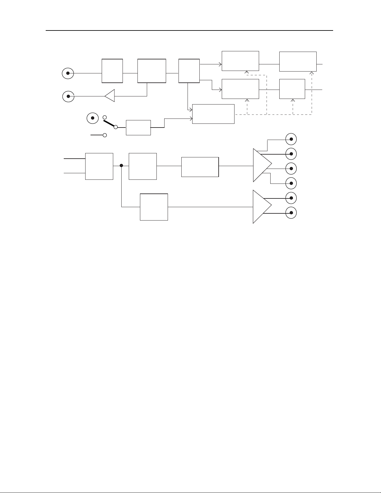
As illustrated in the block diagram on the following page, the serial input to the module
enters a receiver circuit where cable equalization is processed and reported. The signal
then moves through a reclocking and EDH detection circuit where the serial steam is
deserialized, descrambled and EDH monitor detection is performed.
The serial output is sent through cable drivers to the reclocked Serial Out BNC. The
10-bit data stream passes through frame synchronizer memory circuitry where it can be
delayed to one frame. Memory control in this section detects TRS and/or EDH errors and
uses them to determine if an automatic freeze should be performed.
The output from the Frame Synchronizer circuitry is then passed to timing and interpola-
tion circuitry which generates output timing and detects presence of audio ancillary data.
This section also generates the internal black and color bars signals which can be inserted
in the data stream upon loss of signal if desired.
This data stream is then sent to a serial encoder and serializer and EDH is inserted and
updated before going to the four serial output BNCs. The same output is also sent to the
composite encoder where the data stream is converted to composite for viewing on the
monitor outputs.
Power is derived from the ± 12 volt frame power. It is regulated to +5 volts for the module
by on-board regulator. The module is fused with a resettable fuse device. If the fuse opens
due to an overcurrent condition, the module will lose power. After pulling the module, the
fuse will reset automatically requiring no replacement fuse.
Module configuration can be set remotely or locally. The status can be read from the
remote interfaces (Avenue PC or a Touch Screen) or from the LEDs on the front of the
module as explained later in this data pack.
Model 5450 Digital Video Frame Synchronizer
5450-2

Model 5450 Digital Video Frame Synchronizer
5450-3
Serial
Inputs
Serial
Loop-through
Serial
Outputs
Cable
EQ
EDH
Insert
Reclock
& EDH
Detection
Genlock
Input
Master
Internal
Reference
Composite
Encoder
Digital
Sync
Detect
Video
Memory
Embedded
Audio
Memory
Interpolator
Audio
Strip
Control
PLL
Reformat Serializer
Monitor
Output
5450 Digital Video Frame Synchronizer Block Diagram
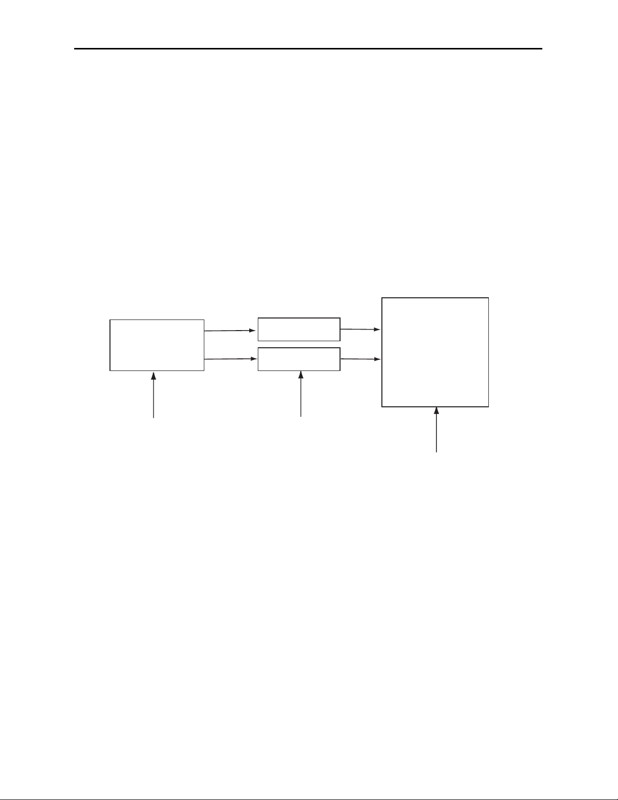
APPLICATIONS
The 5450 Digital Video Frame Synchronizer is ideal for applications where serial (601)
inputs to a device such as a router or switcher require retiming. Serial signal sources such
as satellite feeds, studio signals and timing sources that are not synchronous or are out of
time with the facility can be brought into time and made useful for destinations that have
limited input timing capability or auto-timing windows.
The application below shows the output of a DVE device being retimed in the 5450 to
meet the auto-timing window requirements of a digital production switcher.
The 5450 can also be set to freeze the serial data stream or insert black into it when TRS
or EDH errors occur. This can help overcome frame drops and repeats from unstable
sources. A freeze can be also performed manually or from a GPI contact closure.
The delay value being used on the module can be accessed from the remote interface and
utilized in conjunction with audio delay tracking on another module.
Model 5450 Digital Video Frame Synchronizer
5450-4
5450
5450
DVE
DIGITAL
PRODUCTION
SWITCHER
HOUSE
REFERENCE
HOUSE
REFERENCE
HOUSE
REFERENCE
5450 Retiming Inputs to Production Switcher

Model 5450 Digital Video Frame Synchronizer
5450-5
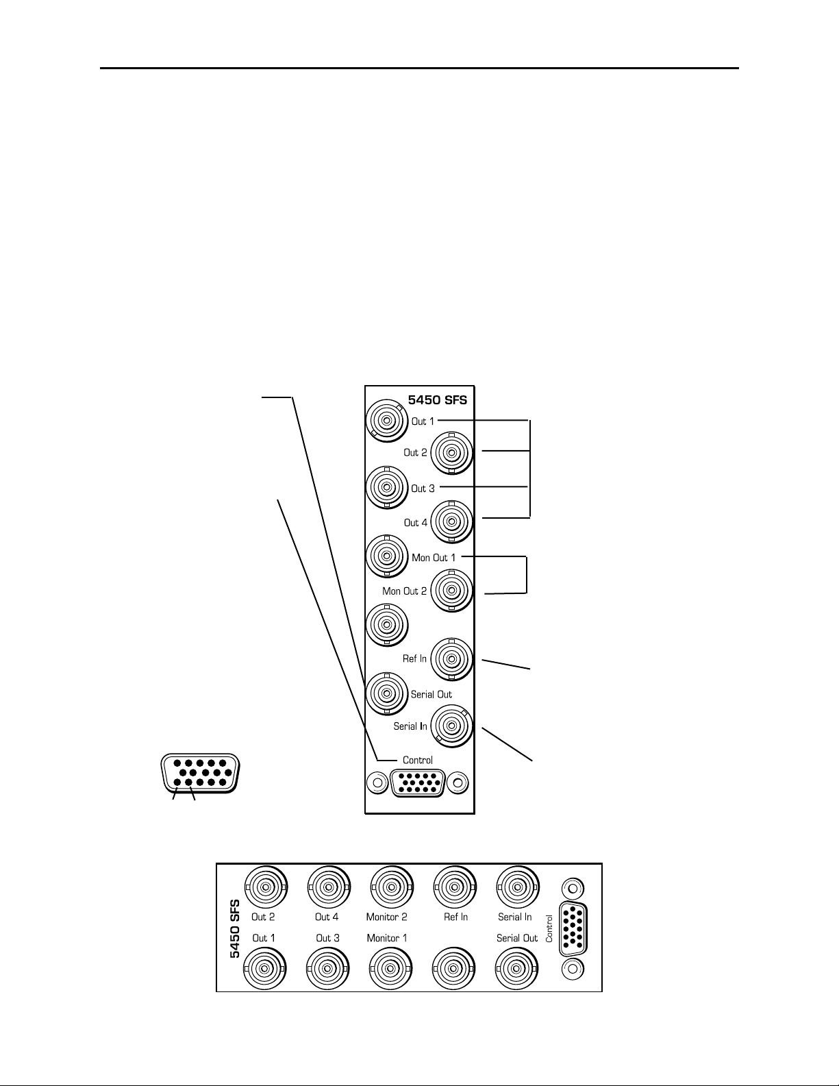
The Control connector can
be connected to an external
GPI device to control image
freezes.
This contact can be triggered
by one of four different states
as configured in the GPI
Mode display in the remote
control Freeze menu. See the
Avenue PC or Touch Screen
sections of this manual.
Connect pin 15 to the external
control output and pin 14 to
ground.
Connect serial
digital destinations
to output BNCs
Out 1 – Out 4.
3 RU Backplane Diagram
1 RU Backplane Diagram
Connect monitor output
BNCs Mon Out 1 or
Mon Out 2 (duplicate
monitor, non-looping
outputs) to a composite
video monitors to view
the signal output.
Connect a video
reference signal to
the Ref In BNC if
using an external
timing reference.
Connect a serial input to
be retimed to the Serial In
BNC. This input can be
non-synchronous.
Use the reclocked serial
input loop-through BNC
Serial Out for looping to
another device.
INSTALLATION
Plug the 5450 module into any one of the slots in the 1 RU or 3 RU frame and install the
plastic overlay provided onto the corresponding group of rear BNC connectors associated
with the module location. Note that the plastic overlay has an optional adhesive backing
for securing it to the frame. Use of the adhesive backing is only necessary if you would
like the location to be permanent and is not recommended if you need to change module
locations. This module may be hot-swapped (inserted or removed) without powering down
or disturbing performance of the other modules in the system.
CABLING
Refer to the 3 RU and 1 RU backplane diagrams of the module below for cabling
instructions. Note that unless stated otherwise, the 1 RU cabling explanations are
identical to those given in the 3 RU diagram.
Pin 15 Pin 14

Model 5450 Serial Frame Synchronizer
MODULE CONFIGURATION AND CONTROL
The configuration parameters for each Avenue module must be selected after installation.
This can be done remotely using one of the Avenue remote control options or locally using
the module front panel controls. Each module has a REMOTE/LOCAL switch on the
front edge of the circuit board which must first be set to the control mode you will be
using.
The configuration parameter choices for the module will differ between Remote and
Local modes. In Remote mode, the choices are made through software and allow more
selections. The 5450 Parameter Table on the following page summarizes and compares
the various configuration parameters that can be set remotely or locally and the
default/factory settings.
If you are not using an remote control option, the module parameters must be configured
from the front panel switches. Parameters that have no front panel control will be set to a
default value. The Local switches are illustrated in the Front Panel Controls and
Indicators section following the 5450 Parameter Table.
Avenue module parameters can be configured and controlled remotely from one or both of
the remote control options, the Avenue Touch Screen or the Avenue PC Application. Once
the module parameters have been set remotely, the information is stored on the module
CPU. This allows the module be moved to a different cell in the frame at your discretion
without losing the stored information. Remote configuration will override whatever the
switch settings are on the front edge of the module.
For setting the parameters remotely using the Avenue PC option, refer to the Avenue PC
Remote Configuration section of this document.
For setting the parameters remotely using the Avenue Touch Screen option, refer to the
Avenue Touch Screen Remote Configuration section of this data pack following
Avenue PC.
5450-6

Model 5450 Digital Video Frame Synchronizer
5450 Parameter Table
Max Cable
Reference Source
Frame Sync
Horizontal Time
Vertical Time
Freeze (manual)
Freeze Mode
Freeze Audio
GPI Mode (Freeze)
LOS Mode
LOS Audio
Setup
Test Signals
0 – 350 meters
External Reference
Master Reference
On
Bypass
±1700 Clocks
±625 lines
On
Off
Field1
Field2
Frame
Mute When Frz
Pass When Frz
Off
High
Low
Toggle High
Toggle Low
Blk on TRS
Blk on TRS32
Blk on EDH
FldFrz on TRS
FldFrz on EDH
Pass on LOS
Mute on LOS
On
Off
Off
Bars
Black
300 meters
External Reference
Switch 1: On
Bypass
0
0
Switch 2: On
GPI
Switch 3: Field1
Frame
Pass
Low
Switch 4: Freeze
Black
Pass
Switch 6: On
Off
Switch 7: Bars
Off
300 meters
External Reference
On
0
0
N/A
Field1
Pass
Off
Blk on TRS32
Pass
On
Off
CONTROL REMOTE
LOCAL DEFAULT/FACTORY
5450-7

Front Panel Controls and Indicators
Front panel controls and indictors for the 5450 module are explained in the diagram
below.
Model 5450 Digital Video Frame Synchronizer
Remote/Local switch:
Set to the mode you
will be using.
In OK green LED:
On indicates the input signal
is present and the equalizer
has detected it.
Pwr green LED:
Indicates the presence (ON)
or absence (OFF) of power
(+5V).
Run green LED:
OFF:
A power fault of halted CPU
ON:
A halted CPU
FAST BLINK:
CPU Run error
SLOW BLINK:
System OK. (If SPI control is
active from the main frame
System Control Module, all
Run indicators will be syn-
chronized.).
5450-8
Frame Sync switch:
On (left) enables frame sync
function. Bypass (right)
disables frame sync.
Freeze switch:
On (left) enables a manual
freeze. GPI (right) enables GPI
control of freeze state.
Field/Frame switch:
Set to Field (left), freeze will
consist of Field 1 and interpo-
lated Field 2. Set to Frame
(right), freeze will consist of the
entire frame.
Freeze/Black switch:
Set to Freeze (left) for image to
freeze when loss of input
signal. Set to Black (right) for
image to go to black when loss
of input signal.
Setup switch:
When On (left) composite
monitor output has setup. Off
(right) no setup on monitor out.
(NTSC only)
Bars switch:
When On (left) internal color
bar generator enabled. Off
(right) color bar generator
disabled.
525 Lock green LED:
On indicates the input deseri-
alizer has locked to a 525 line
rate signal.
625 Lock green LED:
On indicates the input deseri-
alizer has locked to a 625 line
rate signal.
Ref Lock green LED:
On indicates the frame syn-
chronizer is locked to the
selected reference, external
BNC or master.
EDH green LED:
On indicates EDH ancillary
data has been detected on
the input serial stream.
Audio green LED:
On indicates audio ancillary
data has been detected on
the input serial stream.
Freeze red LED:
On indicates frame synchro-
nizer is in freeze mode from
either LOS or manual freeze.
EDH Error red LED:
On indicates EDH error
detected in input data stream.

Avenue PC Remote Configuration
The Avenue PC remote control menus for these modules are illustrated and explained
below. Refer to the 5450 Parameter Table for a summary of available parameters that can
be set remotely through the menus illustrated. For more information on using Avenue PC,
refer to the Avenue PC Control Application Software data pack that came with the option.
5450 Avenue PC Menus
The Input menu shown below allows you to set the following parameters:
•Max Cable – set the maximum amount of cable to be equalized.
•Ref Source – set the input reference to either Master Ref if you are using the
frame reference or External Ref if using the external BNC.
The following displays will report module status:
•Input – gives status of input signal to module.
•Cable Length – reports the amount of cable being equalized.
•EDH Present – indicates presence of ancillary EDH data in the serial data
stream.
•EDH Error – indicates presence of EDH errors in the serial data stream.
•Audio Present – indicates presence of audio ancillary data in serial data stream.
•Reference – indicates the status of the reference as 525/625 Lock, Not Present,
Present not locked, or Present bypass.
5450-9
Model 5450 Digital Video Frame Synchronizer

Use the FrmSync menu shown below to set the following parameters:
•Frame Sync – turn the frame synchronizer function on or off. When on, the output
stream will be timed with the selected reference signal.
•Hor Timing – set the amount of horizontal timing in clocks.
•Ver Timing – set the amount of vertical timing in lines.
The total amount of delay through the module in lines will be reported in the Delay
display. This value may be used in conjunction with other modules to match required
delays.
Model 5450 Digital Video Frame Synchronizer
5450-10

The Freeze menu allows you to determine the freeze functions of the module as listed
below:
•Freeze – allows an instantaneous manual freeze. When the box is checked, the
contents of the frame synchronizer memory are frozen with the attributes chosen in
the other freeze menu displays described below.
•Freeze Mode – select the type of freeze mode either Field1, Field 2 or Frame, a
freeze of the entire frame.
•Freeze Audio – set whether audio is passed or muted during a freeze.
•GPI Mode – determines the operating state of the GPI control connected to the
Control connector on the rear of the module.
The GPI can be configured for High (freeze when pin 15 high), Low (freeze when
pin 15 low), Toggle High (freeze when pin 15 toggles from low to high) or Toggle
Low (freeze when pin 15 toggles from high to low).
The Status window reports the state of the freeze state, either Normal,Freeze, LOS
Mute, LOS Black,orLOS Freeze.
Model 5450 Digital Video Frame Synchronizer
5450-11

The LOS menu shown below allows you to determine the action of the module upon loss of
signal. Set the following parameters from the menu:
•LOS – turn the loss of signal function on or off.
•LOS Mode – set the type of action when there is a loss of signal. You may choose
to replace the signal with black on any TRS error, a TRS error that continues for
32 lines, or an EDH error. Or, you may choose to freeze the video on Field 2 when
either a TRS or EDH error occurs.
•LOS Audio – determines the action to take on the audio channel when a loss of
signal occurs.
The Status display will report the freeze status of the module as either Normal, Freeze,
LOS Mute, LOS Black, or LOS Freeze.
The Monitor menu below allows you to enable or disable setup on the monitor output
(525 line rate only). Select the box for setup on.
Model 5450 Digital Video Frame Synchronizer
5450-12

The Output menu below allows you to set the internal test signal generator to the state
listed below. The test signal passes through the frame synchronizer so the output remains
in the same timing relationship as the chosen reference.
•Off – turns the internal test signal generator off.
•Bars – turns the internal color bars signal on as the module output.
•Black – turns the internal black test signal on as the module output.
Model 5450 Digital Video Frame Synchronizer
5450-13

AVENUE TOUCH SCREEN CONFIGURATION
The Avenue Touch Screen remote control menus for these modules are illustrated and
explained below. Refer to the 5450 Parameter Table for a summary of available parame-
ters that can be set remotely through the menus illustrated. For more information on
using Avenue Touch Screens, refer to the Avenue Touch Screen data pack that came with
the option.
5450 Avenue Touch Screen Menus
The Input menu shown below allows you to set the following parameters:
•Max Cable – set the maximum amount of cable to be equalized.
•Ref Source – set the input reference to either Master Ref if you are using the
frame reference or Ext Ref if using the external BNC.
The following displays will report module status:
•Input – gives status of input signal to module.
•Cable Length – reports the amount of cable being equalized.
•EDH Present – indicates presence of ancillary EDH data in the serial data
stream.
•EDH Error – indicates presence of EDH errors in the serial data stream.
•Audio Present – indicates presence of audio ancillary data in serial data stream.
•Reference – indicates the status of the reference as 525/625 Lock, Not Present,
Present not locked, or Present bypass.
Model 5450 Digital Video Frame Synchronizer
5450-14

Use the FrmSync menu shown below to set the following parameters:
•Frame Sync – turn the frame synchronizer function on or off. When on, the output
stream will be timed with the selected reference signal.
•Hor Timing – set the amount of horizontal timing in clocks.
•Ver Timing – set the amount of vertical timing in lines.
The total amount of delay through the module in lines will be reported in the Delay
display. This value may be used in conjunction with other modules to match required
delays.
Model 5450 Digital Video Frame Synchronizer
5450-15

The Freeze menu allows you to determine the freeze functions of the module as listed
below:
•Freeze – allows an instantaneous manual freeze. When the box is checked, the
contents of the frame synchronizer memory are frozen with the attributes chosen in
the other freeze menu displays described below.
•Freeze Mode – select the type of freeze mode either Field1, Field 2 or Frame, a
freeze of the entire frame.
•Freeze Audio – set whether audio is passed or muted during a freeze.
•GPI Mode – determines the operating state of the GPI control connected to the
Control connector on the rear of the module.
The GPI can be configured for High (freeze when pin 15 high), Low (freeze when
pin 15 low), Toggle High (freeze when pin 15 toggles from low to high) or Toggle
Low (freeze when pin 15 toggles from high to low).
The Status window reports the state of the freeze state, either Normal,Freeze, LOS
Mute, LOS Black,orLOS Freeze.
Model 5450 Digital Video Frame Synchronizer
5450-16

The LOS menu shown below allows you to determine the action of the module upon loss of
sync. Set the following parameters from the menu:
•LOS – turn the loss of signal function on or off.
•LOS Mode – set the type of action when there is a loss of signal. You may choose
to replace the signal with black on any TRS error, a TRS error that continues for 32
lines, or an EDH error. Or, you may choose to freeze the video on Field 2 when
either a TRS or EDH error occurs.
•LOS Audio – determines the action to take on the audio channel when a loss of
signal occurs.
The Status display will report the freeze status of the module as either Normal, Freeze,
LOS Mute, LOS Black, or LOS Freeze.
The Monitor menu below allows you to enable or disable setup on the monitor output
(525 line rate only). Select the box for setup on.
Model 5450 Digital Video Frame Synchronizer
5450-17

The Output menu below allows you to set the internal test signal generator to the state
listed below. The test signal passes through the frame synchronizer so the output remains
in the same timing relationship as the chosen reference.
•Off – turns the internal test signal generator off.
•Bars – turns the internal color bars signal on as the module output.
•Black – turns the internal black test signal on as the module output.
Model 5450 Digital Video Frame Synchronizer
5450-18

TROUBLESHOOTING
As a troubleshooting aid, the input and reference signal, EDH, audio, freeze, EDH error,
power and CPU status can be easily monitored from the front panel of this module using
the LED indicators explained earlier.
If using the Remote mode, the following status items can be monitored using the Avenue
Touch Screen Control Panel or PC Application:
• Input, EDH, Reference and Audio present status
• EDH error status
• Loss of signal (LOS) status
• Slot ID, Software Version and Board Revision
Refer to the overall troubleshooting tips given below for the 5450 module:
No status lights are lit on front panel:
• Check that frame power is present (green LED{s} on frame power supplies).
• Check that module is firmly seated in frame. Try removing it and plugging
it in again.
Can’t control module:
• Check status of CPU Run green LED. Should be blinking slowly and in
unison with other modules if System module is present. If not, try removing
it and plugging it in again.
• System module may not be working properly if installed.
• Check that the Local/Remote switch on the front of the module is set to the
correct operating mode.
No signals out of module:
• Check status of In OK green LED. Should be lit. If not, check the input
signal for presence and quality.
• Check for presence and locking of reference signal.
• Enable test signal from local or remote control to test signal path.
• Check cabling to input of module.
• Check remote cable equalization by switching the module to Local using
the front panel switch.
You may also refer to the technical support section of the Ensemble or Graham-Patten
web sites for the latest information on your equipment at the URLs below:
http://www.ensembledesigns.com/support
http://www.grahampatten.com
SOFTWARE UPDATING
Software upgrades for each module can be downloaded remotely if the optional System
Control module is installed. These can be downloaded onto your PC and then Avenue PC
will distribute the update to the individual module. (Refer to the Avenue PC documenta-
tion for more information) Periodically updates will be posted on our web site. If you do
not have the required System Control Module and Avenue PC, modules can be sent back
to the factory for software upgrades.
Model 5450 Digital Video Frame Synchronizer
5450-19

WARRANTY AND FACTORY SERVICE
Warranty
This Module is covered by a five year limited warranty, as stated in the main Preface of
this manual. If you require service (under warranty or not), please contact Ensemble
Designs or Graham-Patten Systems and ask for customer service before you return the
unit. This will allow the service technician to provide any other suggestions for identifying
the problem and recommend possible solutions.
Factory Service
If you return equipment for repair, please get a Return Material Authorization Number
(RMA) from the factory first.
Ship the product and a written description of the problem to:
Ensemble Designs, Inc.
Attention: Customer Service RMA #####
870 Gold Flat Rd.
Nevada City, CA. 95959 USA
(530) 478-1830
Fax: (530) 478-1832
http://www.ensembledesigns.com
Be sure to put your RMA number on the outside of the box.
OR
Graham-Patten Systems, Inc.
13366 Grass Valley Avenue
Grass Valley, CA 95945
(800) 422-6662 or (530) 273-8412
Fax: (530) 273-7458
http://www.grahampatten.com
Model 5450 Digital Video Frame Synchronizer
5450-20
Table of contents
Other Ensemble Designs Recording Equipment manuals
Popular Recording Equipment manuals by other brands

Linear Acoustic
Linear Acoustic MetaMAXLA-5180 Operation manual

Panasonic
Panasonic NV-HD610EG Service manual

ASL INTERCOM
ASL INTERCOM WS-19 user manual

Mackie
Mackie SDR24/96 quick start guide

myMix
myMix Networkable personal audio mixing and recording... owner's manual

Sonoclast
Sonoclast MAFD 2hp user manual