16
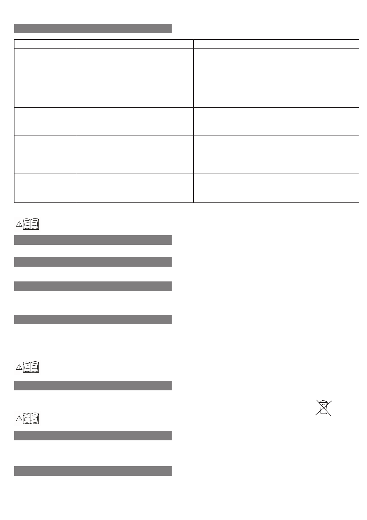
3. Failure Delection
Breakdown
Fluid is leaking
The analog isn't giving
signal or it's giving the
incorrect value.
Housing or body broken
There is an Unstable
work in the signal.
The thread is stripped.
Probable cause
-Hole in the body metarial.
-The socket may not contact
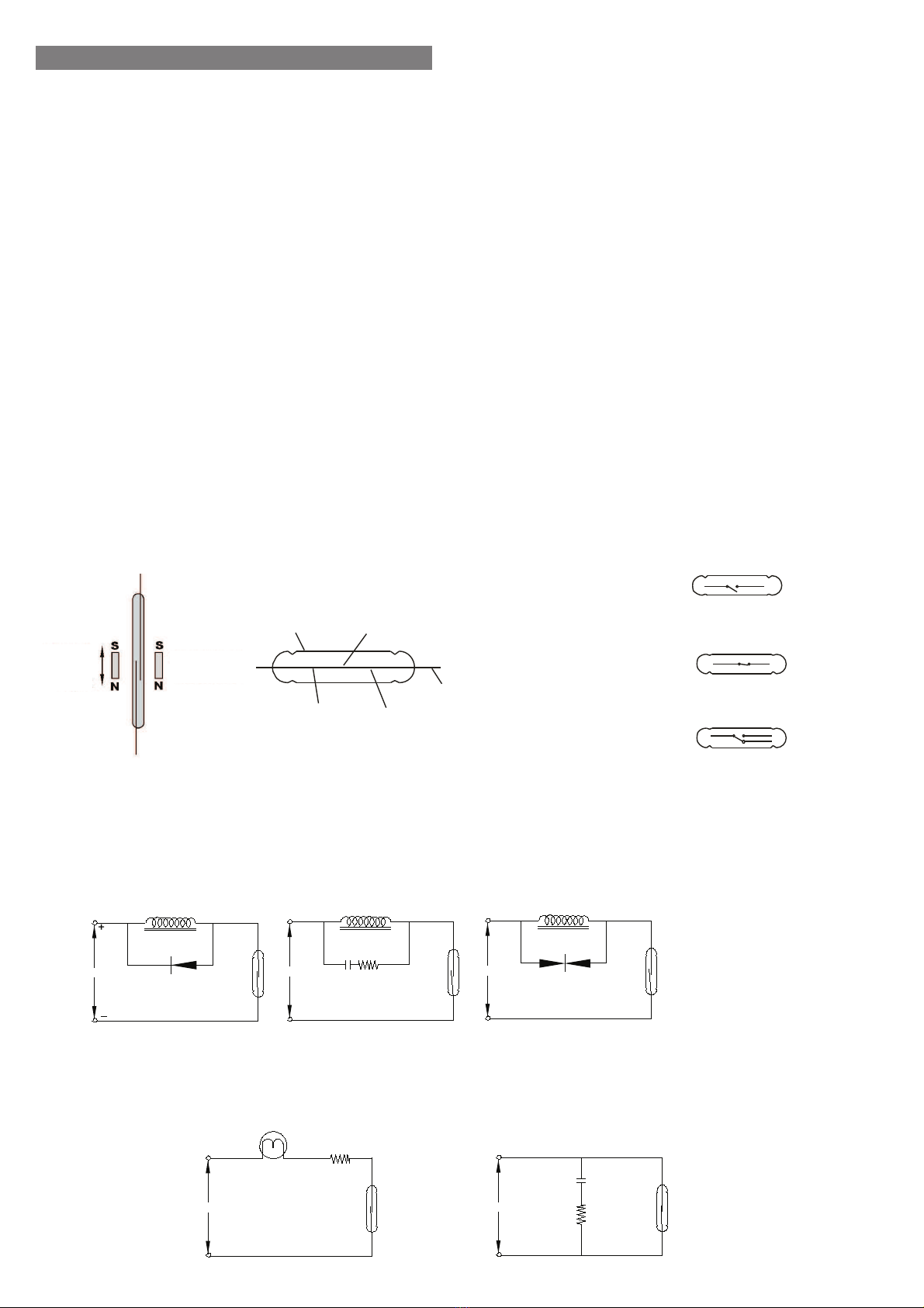
-The product has been exposed in a mangetic
ambient.
-Angle of connection is not right.
-Applied voltage above the value.
-Over tightening the screws during installation
-Product falling or impact from outside.
-The product has been left in a magnetic ambient.
-The product has been exposed in a vibration.
-Product exposure in high temperature.
-Been tightend with torks more than specified
during installation.
Failure detection\correction
-Check if their working under favorable conditions ,
contact the manufacturer.
-Check the socket connections.
-The magnetic field element must be removed or isolated.
-Fix the angle of the montage.
-Report to authorized service.
-Report to authorized service.
-The magnetic field element must be removed or isolated.
-Vibrations must be blocked from that will effect the product or must
connect where there is no vibration.
-Use in suitable temperature.
-Report to authorized service.
If you find an error, try to eliminate it by using this table or send the instrument to our service address for repair.
The instrument should be repaired only by authorized service! Serial number shall be indicated to the authorized service center.
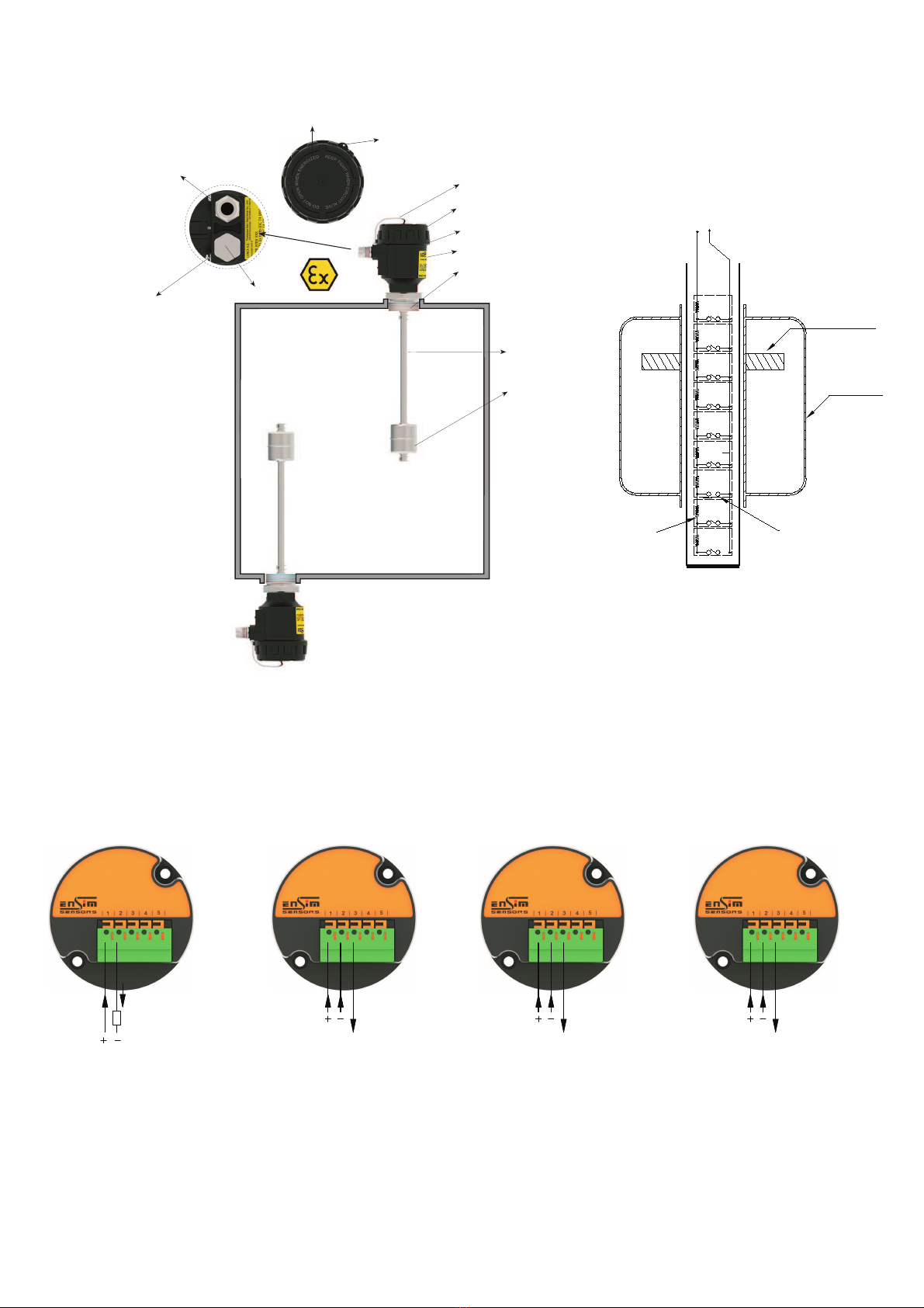
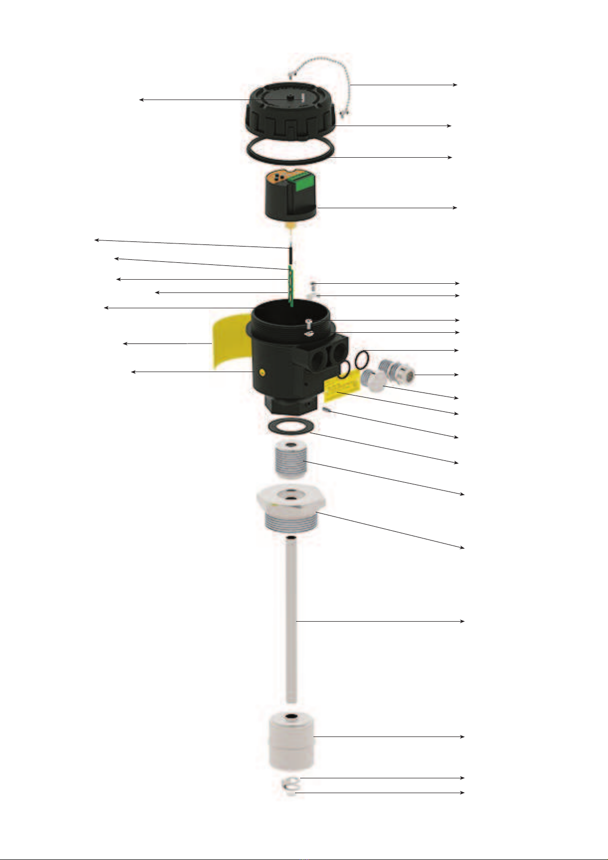
4. Disassembly of Instrument
Instrument should be disassembled while feeding and pressure is not available!
5. Service
6. Re-Calibration
During long period usage of level switch, there might be deviations on measurements. In those cases, recalibration is recomended. Re-calibration could be made by your
technical staff or you could send to manufacturer company. According to IEC 60017, ex proof devices must be go through detailed inspection every 3 year from purchase
date.Respobsibility of inspections are belong to the user ( IEC: International Electrotechnical Commission)
7. Repair Manufacturer Address
If irreparable breakdowns occur, the instrument should be sent to us for repair purpose. Before this, the instrument should be cleaned carefully and packaged
so as not to be broken. Furthermore, you should also add a detailed explanation which describes the breakdown while instrument is sent. If your instrument
contacts with harmful substances, decontamination report should be also sent additionally. In the event that instrument does not have any decontamination
report or our service department has doubts about instrument, repair process will not start until an acceptable report is sent.
8. Disposal
The instrument should be disposed according to 2002/96/EC and 2003/108/EC European Directives (waste electrical and electronic instruments).
Waste electrical and electronic equipment should not be mixed with domestic wastes!
If the instrument has contacted with harmful substances, special attention should be paid for its disposal!
9. Terms of Warranty
The instrument has warranty legally for 24 months after delivery date. Warranty demands are not accepted in case of inappropriate operation, damage on the
instrument or any modification on the instrument.
10. Terms of Return
In the return of materials, user should send an open list related to damage or problem, malfunction of the material to be returned or its operation in the different
modification, with the instrument. If it is required to return the material, used in the dangerous, corrosive or toxic fluid, in this case, used part should be cleaned
very carefully. Security of personnel should be ensured. All products to be returned should be sent to our company address, which
we have stated.
The instrument does not require maintenance. If it is desired, residue accumulated inside should be blown according to kind of fluid and instrument can be cleaned
with soft cleaning solutions. Measures should be taken during the disassembly.
If the instrument contacts with hazardous substances, necessary measures should be taken for decontamination!
Service -Manufacturer Company Name and Address:
LONCA PAZ. MAK. SAN. TÝC. A.Þ.Ferhatpaþa Mah. Gazipaþa Cad. No:104A - P.K. 34888 Ataþehir - ÝSTANBUL - TÜRKÝYE
Phone:+90
216
50
50
555
Pbx
-
Fax:+90
216
515
45
84
E-Mail:
[email protected] Web:
www
.ensim.com.tr