ENSIM SENSORS EGW Series User manual

1
OPERATING
MANUEL GUIDED RADAR (TDR) TYPE LEVEL TRANSMITTER
EGW
Model :
Model : 80-2021-001
Information in this manual is reviewed and completely reliable. esponsibility is not assumed due to any typing error.
Products in this manual are available only for information purpose and they may be changed without notice.
Important Notes:
Used Symbols :
: Caution : Note : Disposal
Please read this manual carefully before installation of the Guided Radar (TRD) Type Level Transmitter. User is responsible
for accidents and losses arising from failure to comply with the warnings in this manual.
In the event that Guided Radar (TRD) Type Level Transmitter is broken, take measures in order to prevent accidents and l
osses which can occur in its system.
There is not any fuse and circuit breaker on the instrument; they should have been added to the system by the user.
This manual should be stored in an easily accessible place for subsequent use.
The manufacturer's liability cannot exceed the purchase price of the device according to the law.
Do not make any modification on the instrument and do not try to repair it. eparation should be made by authorized service staff.
Do not operate the system before making assembly in compliance with the assembly chart related to the instrument.
Products which do not contain label and serial number are considered to be excluded from the warranty scope.
The instrument's useful life, determined and announced by the ministry, is 10 years.
Table of Contents :
General Information...........................................................................................................................................................................
Installation .........................................................................................................................................................................................4
Failure Detection.............................................................................................................................................................................. 3
Disassembly of Instrument ............................................................................................................................................................ 3
Service ............................................................................................................................................................................................. 3
Recalibration.................................................................................................................................................................................... 3
Repair................................................................................................................................................................................................ 3
Disposal ........................................................................................................................................................................................... 3
Terms of Warranty .......................................................................................................................................................................... 3
Terms of Return ................................................ 3
1.
.
3.
4.
5.
6.
7.
8.
9.
10.
Models :
EGW 04, EGW 05
EGW 0 , EGW 03
EGW 01, EGW 07
EGW 0S

1. General Information :
1.1. Material Acceptance
Check that there is no damage on the packages during the transportation immediately after the material acceptance. If packages are
damaged, open the packages immediately and check whether products are affected or not, if there is any damage, send your
complaint report to the transporter company and its photocopy to the address of our company.
1. . Information about Areas of Use
Volatile liquids, foamy liquids, viscous liquids, boiling and foaming liquids, crude oil vessels.
Misusage :
Incorrect or improper use may impair the performance of the device or cause damage to the device or personnel, for example due to improper
installation or adjustment, the installation of a non-corrosive device for the corrosive environment, the field condition does not comply with the
technical specification limit value of the device. The manufacturer is not responsible for damage caused by incorrect or improper use.
We do not recommend using this device when the device is operated incorrectly or misevaluates the echo caused by special mounting conditions.
In the event that the user violates the warning, the manufacturer is not responsible for the relevant damage.
The Device Fullfills the equirements of the Following Directive.
. Low Voltage Directive 2006/35/EC
. EMC Directive 2004/30/EC
. EN 61010-1
. EMC specification acc. to EN 61326/1
Advantages :
In compact structure
Easy to commission
Durable mechanical structure
High temperature versions are available
Ambient Conditions; elative Humidity:5-98 % H Ambient temperature: 60°C (not used below -40 °C)
1.4. Label Information :
Grounding Label
:
:
:
:
:
Type : EGW 204-500-0-0010-19-702-066-001-00/0
Power Supply
Output
Process Temp.
T (Ambient)
Serial Number
TDR RADAR LEVEL TRANSMITTER
24VDC +/- %10
4-20mA Two Wire
-40 / +200 °C
-20...+60 °C
IE18040002-0001
www.ensim.com.tr
MADE IN TURKIYE
Warning
Symbols
Manufacturer
Website
1.3. Working Princible
Microwave pulses emitted by the antenna of the radar move at the speed of light and as part of its energy, reflected by the surface of the medium
to be measured, recieved by the same antenna. The time between the emission and the arrival of the pulses (flight time) is proportional to the available
distance between the antenna and the surface of the medium to be measured.
The electromagnetic wave travels at a very high speed (nanoseconds) so it is difficult to describe it. Guided adar (T D) Type Level transmitter
determine the emission and corrected capacity of pulses and consequently the level measurement with a suitable demodulation tehcnology that enables
them to detect the between them, thanks to their integrated management systems. The alphanumeric display not only allows the user to input data for level
measurement, but also separates false echoes.
Model
Serial Number
Ambient Conditions
Supply
Output
Working Temperature
Product Label
Approval SignManufacturer Brand Product Name

1.5. Technical Specifications and
Material Information:
3
Technical Specifications
Cover Setscrew
Cover
Cover Seal
Housing Body
Product
Label
Grounding
Label
Connection
ecord
Probe
Electronic Unit
Indicator
Cable Gland
Tapa
Grounding
Terminal
Liquid , Solid Particulate Materials, Agressive Liquids
32 m. ope Probe
6 m. od Probe
4 m. Coaxial Probe
English
± 3 mm
± 1,5 mm
1 mm
(-)1...(+)40bar , Opt. Max. 100bar
(-)40...(+)200°C , Opt. Max. 450°C
(-)20...(+)60°C
106 MHz - 1,8 GHz
Min. 1,4 (Different intervals can be selected.)
<2 sec.
16 Hz
<0,5 W
15...36 VDC Two-wire version ( esolution 1,6 micron A)
4-20mA Two-wire + HA T
20,5 mA , 22mA , 3,9 mA (Adjustable)
500 W
0...90 sec.
Aluminium Injection AISi2Fe Black ( AL9005) / Plastic (PP)
Stainless Steel (Std.), Ops. 316 Stainless Steel
PTFE (Std.), Ops. PEEK, Ceramic
LCD Display
M20 x 1,5 mm
With Terminal
IP66 (EN60529)
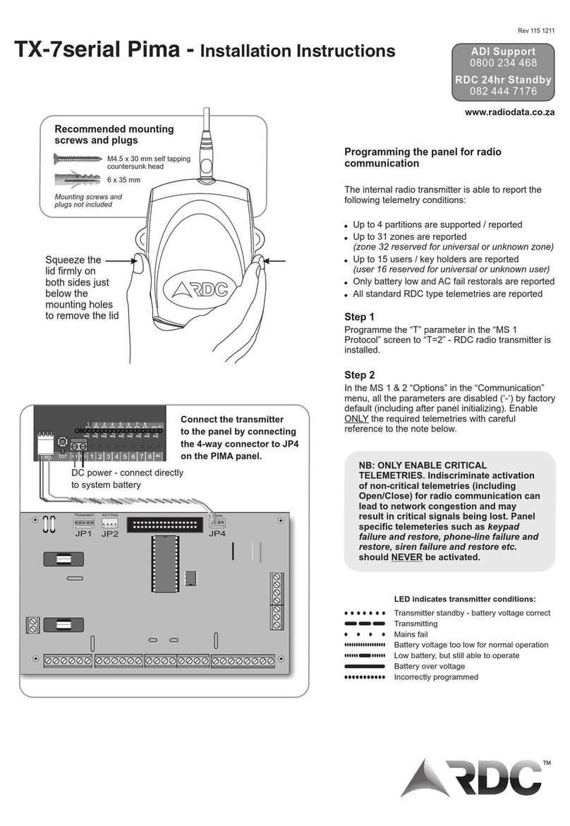
EGW 205, (For L=1000mm ) ... kg
Material to be Measured
Measurement Field
Setting Menu Language
Sensitivity
epeatability
esolution
Working Pressure
Working Temperature
Ambient Temperature
Frequency
Dielectric Constant (E)
esponse Time
Sampling Frequency
Power Consumption
Supply Voltage
Output Signal
Fault Signal
Max. Load esistance
Damping Time
Housing Material
Connection and Probe
Material
Insulation Material
Indicator and Adjustment
Cable Input
Electrical Connection
Protection Class
Weight
Tapa
Aluminium Housing
Grounding Terminal
(Max1,5 mm²)
ecommended cable (5x1,5 mm²)
Cable Fitting
(Suitable cable diameter: Ø 6-12mm)
DO NOT OPEN THE COVE WHEN
ENE GY IS AVAILABLE
KEEP IT CLOSED WHILE OPE ATING
M3
In damp and humid areas, cable fittings should
be tightly tightened, replace at regular intervals,
and in order to prevent water leakage into
the sensor body in case of deformations that
may occur over time, the cable should be left
in a downward sloping position at the gland inlet.
Damp-proof
1.6. Housing :
B21x
a
b
MATERIAL PROTECTION
CLASS TEMPERATURE
(°C)
TYPE
B21x Aluminium IP 66 (-) 40...(+) 200
SIZE
a x b (mm)
140 x 104
ORDER
CODE
702
B20p Plastic (PP) IP 66 (-) 40...(+) 150 132 x 104103

.1. General Notes
The installation of the device should only be carried out by qualified personnel.
Do not apply force to the device during installation!
Do not use the Guided Radar (TRD) Type Level Transmitter at higher pressure than the recommended one.
Do not forget that the contact setting of the device is sensitive, handle it carefully and prevent it from getting damaged.
It must be guaranteed that there are no magnetic particles.
. . General Installation Stages
* emove Guided Radar (TRD) Type Level Transmitter from the box carefully
*Check whether gasket is appropriate for fluid or not. If is not appropriate, contact with the producer.
*Then, apply below mentioned explanations according to structure of the design.
.3. Special Notes
*Please make sure that there is no mechanical stress on the shaft after installation. Such a situation will lead to a shift in the characteristic curve.
*Guided Radar (TRD) Type Level Transmitter should be placed in a vertical position on the line.
*If the device is installed outdoors and there is a danger of lightning or overpressure, we recommend to install an effectively sized overpressure
protection between the supply cabinet and the device.
*Under operating conditions, the Level Transmitter may be hot depending on the condition of the fluid, in this case, do not touch the transmitter,
your skin may be damaged.
.4. Installation For Mechanical Connections
*Use appropriate O-ring or seal for sealing.
*Make sure that its surface is clean and smooth.
*Install the device manually.
*Tighten the key as shown in the figure.
(Max. 20 Nm. For stainless models)
4
2. Installation:
.5. Apparatus :
Cooler :
Malzeme : 304 Stainless Steel
Welded manufacturing
Applicable to all models except for EGW 20S.
Process temperature max. for 250°C
105
Protection Cover
:
Material : 304 St. steel
Welded manufacturing
Open Close Hinged
To protect the switch against
external conditions.
By-Pass Tube
304 Stainless Steel
Welded manufacturing
1.7. Target Group
This user manual has been prepared for qualified technical personnel.
1.8. Safety Notes
The following notes should be taken into account to avouid hazards to the operator and its surroundings.
The installation, use and maintenance of this device should only be carried out by people who have read the user manual and have knowledge
of work safety!
Work safety, accident prevention regulations and national installation standards must be complied with.
The product should only be used within the stated specifications!
You can only mount the device when there is no pressure!
1.9. Package contents :
Please check whether you have taken delivery of below listed content completely or not and check its conformity with criterions
in your order:
* Guided adar Type Level Transmitter
* This operating manual

The measurements maximum level, is the thread seal position or flanges bottom surface.
When the liquid or solid level is full, enter the dead zone correctly otherwise the instrument will not be able to measure the level effectively.
Mounting site selection
K1
XX
K3
K2
.6. Mounting Requirements
During the installation , while the tank is empty, false echo detection should be made and the surfaces that create faulty echo should be
recorded by the sensor. In this way, the sensor does not detect these points as a level and the measurement continues properly.
Care should be taken that the product entering the tank does not pass over the signal line of the sensor when filling through the silo or tank.
There is a blind area that cannot be measured by the sensors and known as the dead zone just below the antenna, which does not exceed
5 cm according to the sensor. It is important that the product does not pass over the sensors dead zone during filling, in which case
the sensor will fail or the measurement values may remain constant.
Hooter
S 485
4...20 mA / 0...10 V / 1 - 5 V /..
1 / 2 / 3 / 4
A B CD
Min 50mm
E
%100
%0
L= Measurement Site
A
B
C
D
E
:
:
:
:
:
Min. Dead Zone
Max. Dead Zone
Max. Level Min. Measuring Distance
Min. Level Max. Measuring Distance
Datum Plane
For K1 (mm);
Flat metal wall > 50 mm
Plastic wall > 300 mm
Flat wall > 500 mm
For K (mm);
ope Probe > 150 mm
od Probe > 10 mm
Coaxial Probe > 10 mm
For K3 (mm);
Connection Sleeve : min 100mm
Support may be required if the probe lenght is more then 3 meters.
5

6
Mounting site selection
Safe Rope Probe
You can fix the probe with the outer tube
to prevent the rope probe from shaking.
Safe Rod Probe
Support is required when the probe
length is more than 3m. However,
in strong fluctuating conditions,
the probe tip should be fixed to the bottom
of the vessel with a special device.
Safe Coaxial Probe
You can fix the probe with the outer tube
to prevent the coaxial probe from shaking.
Funnel Type Flange
When the head height is more than
200 mm, the vessel wall will affect
the measurement. Use metal funnel
flange to reducee impact.
Large Diameter Head
1- Auxiliary signal plate with a
diameter of 100 to 150.
2- Auxiliary signal plate
3-Mounting head face and
auxiliary plate face must be
aligned.
Extension Rod and Boundary Ring
For long mount hood, extend the probe
or rope antenna so that it protrudes into
the vessel and fix it to prevent shaking.
Non-metal chamber mounting
1 Metal plate or metal flange
2 Non-metal vessel wall (plastic, glass or wood).
To ensure the reliability of the measurement ,
the guide radar level transmitter requires a metal
surface at the process connection. When mounted
in a non-metallic vessel such as a plastic vessel
or a glass vessel, use a flange and position a metal
plate under the process fitting. Make sure that the
plate is in direct contact with the process fitting.
1
2
1
3
2
1
2
Extension Rod or
Rope
Line Ring
1

7
Guide radar level transmitter tube recommendation:
For boat setup and turbulent conditions, the sensor should be mounted with a guide tube.
The material must be metal.
Constant diameter
Mark the polarization on the sensor.
Guide tube diameter should be larger than antenna diameter.
The diameter difference between the coaxial tube and the inside diameter of guide radar level transmitter tube is as small as possible.
Weld seam as smooth as possible and in line with the slit.
The slot width or hole diameter is less than or equal to 5 mm, it is smooth.
Length and number have no effect on the measurement.
The antenna diameter of the sensor should be suitable for the inner diameter of the pipe.
The inner wall of the guide wave tube should be straight and without a weld seam.
Since the sensor only measures the inner level of the tube, the waveguide tube should descend to the desired level.
Threaded Connection Mounting
The sleeve length should not be less than 100 mm.
The inner diameter of the sleeve must be at least 1 1/2'BSP
Dalga kýlavuzu tüpüne montaj
For boat setup and turbulent conditions, you can mount the sensor with the waveguide tube. For best measurement,
he diameter of the antenna should be close to the diameter of the waveguide tube.
What should a waveguide be like ?
-The material must be metal.
-The diameter must be constant.
-Polarization must be marked on the sensor.
-Waveguide tube diameter should be larger than antenna diameter.
-The diameter difference between the outer diameter of the radar antenna and the inner
diameter of the waveguide tube should be as small as possible.
-The source point should be as smooth as possible and on the same axis.
-Duct width or hole diameter less than or equal to 5 mm, without burrs. Length and number have no effect on the measurement.
-The antenna diameter of the sensor should be suitable for the inner diameter of the pipe.
-The inner wall of the guide wave tube should be smooth and there should be no welding seams.
-The guide tube length should not be more than the sensor antenna length.

8
Mixer Application;
Correct
If there is a mixer in the vessel where the sensor will measure the level,
the sensor should be mounted at a point away from the filling line and
as far as possible from the mixer that blocks the signals.
False signals reflected from the propellers of the mixer in the vessel
may reach the sensor and cause the sensor to make an incorrect evaluation.
In such cases, when the vessel is empty, erroneous signals must be detected
and false signal suppression must be applied. Thus, the sensor is prevented
from making incorrect measurements in case of faulty signals.
Installation Site Selection
Correct: Mount the sensor as far from the filling point as possible.
In terms of its lifetime, use protectors to keep it away from snow,
rain, sun and similar factors when necessary.
Wrong: Do not place the sensor on the fill line. The signal line
must see the surface to be measured.
CorrectWrong
By-Pass Application
If there are difficult physical factors such as mixer, ladder,
vessel reinforcement metals in the vessel where the sensor
will measure, By-Pass Application is required. In this way,
accurate and reliable measurement is provided .
Correct
Ø50mm rod antenna
For best measurement, the tip of the antenna should protrude
at least 15 mm outside of the vessel.
>15mm

9
HA T Communication, with Hand Terminal
Power Supply
4VDC
HA T
Hand Communicatior
esistance 50 W
.7. Electrical Connection
DC energy between 1436V is required as the power supply. The outer diameter of the cable bringing the energy should be between
59mm, with at least two wires and, if necessary, shielded type to protect it from electromagnetic fields. 420mA analog output
signal is also received through the same cable.
Two-wire 4... 0mA HART protocol
4 VDC Supply
4-20 mA
1
Load resistance diagram (Two-wire version)
14 19
50
800
1100
4 6 8 30 3 34 36
Supply Voltage
HA T
Load
Load Cable esistance + HA T esistance + Load esistance
Voltage Limit
W
15 18

10
For mounting the display and adjustment module;
1 emove the housing cover.
2 Position the display and adjustment module in the target position.
3 Screw on the housing cover.
.8. Display and Adjustment Module
-Switch between menus
-Change values, switch between values
-Move the enlarge wave edge logo to the left.
-Change Numbers / Values
-Switch between menus
-Swþtch between values
-Move the enlarge wave edge logo to the right
-Switch between steps
ESC -Back to the next upper menu
-Back to the main menu
-Switch to the graphic display
OK
-Enter the main menu
-Enter the selected menu
-Save the values
-Edit parameter
.9. Setting Options
adar Level Transmitter Display can be adjusted with the following adjustment media:
a) With local display and adjustment module
b) Tank side monitor
c) Setting software on upper monitor
d) HA T communication
e) OSEMOUNT 375 / 475 (only for hart common position)

11
Quick Setup
Basic Setup
Display
System
Linearization
Security
Communication
Diagnosis
System Info
ecord Curve
A - QUICK SETUP
Min. 0.00%
20.000 m
Min. 0.00%
25.000m
Max. 100%
0.0000 m
Maz. 100.00%
0.5000m
Min. and Max. Level Adjustment
A - QUICK SETUP : Level Confirm
Level Confirm
3.3
2.2
1.1
0.00 0.00 6.00 12.00
V1.05 16.67 6.500
1- Select Quick Setup menu item and confirm with OK.
Select Level Confirm and confirm with OK.
Echo trend will be displayed as follows:
Cable Lenght :
20.000m
A - QUICK SETUP:
B - BASIC SETUP :
C - DISPLAY :
D -SYSTEM :
E - LINEARIZATION :
F - SECURITY :
G - COMMUNICATION :
H - DIAGNOSIS :
I - INFORMATION :
J - RECORD CURVE :
The radar sensor can measure the level accurately for most field conditions with quick setup.
You can set the maximum level, minimum level and level confirmation.
Settings, eg. Damping time, Dielectric constant, Max. Dead zone, Min. Dead zone, Speed change, Magnification times
Settings, eg. Display value, Unit, LCD contrast, Language
Settings, eg. Echo decision, Current caliber, Distance caliber, Distance coefficient, Mapping setting
Settings, eg. Distance linearity selection, Distance linearity regulation, atio linearity selection, atio linearity regulation
Settings, eg. Echo loss adjustment, Skip processing, Current output, Parameter protection
Settings, eg. Address type
Information, eg. Distance record, Number of restarts
Information, eg. Production date, Serial number, Part number, Version number
Information, eg. Echo curve , Measurement curve
The device is adapted to the application conditions through parameter adjustment. Parameterization is carried out via a settings menu.
The main menu is divided into ten seconds with the following functions:
.10. Operation Menu Structure and Function
1 - Select the menu item Quick Setup and confirm with OK.
Min. 0.00% Press the OK button to change the distance value,
use the arrow keys to change the values.
Confirm the determine value with OK.
Enter the appropriate distance value in m for the full tank
Max. Level is the distance from the farthest point of the antenna
part to the tank max. level. It cannot be more than the min. level distance.
2 - With switch to Max. Level Adjustment menu.
Press OK button to change Max. % 100,00 Distance value,
Use the arrow keys to change the values.
Confirm the determined value with OK.
Enter the appropriate distance value in m for the full tank.
Max. Level is the distance from the farthest point of the antenna part to the tank max. level. It cannot be more than the min. level distance.
3- With select Cable Length menu. Confirm with OK.
Value can be adjusted between 0.1000 ~ 32.000 m. Save the adjusted value with OK.

1
B - TEMEL KURULUM (Basic Setup) :
2- Press OK key, the menu is as follows:
Zoom X: Extend the X plane for better observation
Zoom Y: Extend the Y plane for better observation.
No zoom: estore planes.
Setting range: You can select the Start , End, Confirm points to adjust the displayed range.
X zoom in
Y zoom in
No zoom in
Display range
Min. dead zone
Max. dead zone
Change Speed :
0.4000m/s
Min. Dead Zone:
25.000m
Quick setup
Basic Setup
Display
System
Damping Time :
0.5S
Dielectric Constant:
2.5-4
Max Dead Zone:
0.0000m
Magnification Times:
15
1- Temel Kurulum menü öðesini seçin ve OK ile onaylayýn
7- With switch to the Magnification Times menu confirm
with 'OK. Select and save the value between 0 and 80. 15
is the standard value.
2- Extinction Time menu is displayed. Press the OK key to jump from
cursor to value. You can set the suitable value between 0 ~ 99S.
Save the value with OK. It is used to determine the range of variation
of measurement values. Time can be kept high in fluctuating tanks.
3- With change to the menu Dielectric Constant with OK.Confirm with OK.
Select the appropriate range of values for the Dielectric Constant in accordance
with the measured liquid or solid. Save with OK.
There are six options : >7, 4 ~ 7, .5 ~ 4, 1.9 ~ .5, 1.6 ~ 1.9, 1.4 ~ 1.6.
4- With change to the Max. Dead Zone menu confirm with OK
Enter the appropriate value according to the application. Confirm with OK.
5- With change to the Min. Dead Zone menu with OK.
Set the appropriate value.
6- With change to the Change Speed menu with OK. Set the appropriate
value according to the application. Confirm with OK. Enter the appropriate
value according to the level filling speed. Save with OK.

13
D -SÝSTEM (System): Yanký Seçimi (Echo Judge)
Quick setup
Basic Setup
Display
System
Display Value :
Level
Display Unit :
Meter
LCD Contrast:
Do you adjust?
Language:
English
Echo Judge
Current Calibr
Distance Calibr
Distance Coeff
Mapping AdjustQuick setup
Basic Setup
Display
System
Largest
Foremost
Sucession
esolution
Superiority
0.0300V
Comfirm Time
10,000s
Min. esolution
0.2000V
Logic Select
1- Select the Display menu and confirm with OK
2- You can select the values to be seen on the screen from the Display Content.
Login with OK. Select one of the options of Level, Current, Distance, Percent
and Mapping and confirm with OK.
3- Select the Display Unit menu with key and enter with OK. Unit selection
is made for Level and Distance in this field. Make a selection with the
arrow keys and confirm with OK.
4- Select the menu LCD Contrast with the key and enter with OK.
Make the setting with the keys . Confirm with OK.
5- Select the menu Language with the key and confirm with OK. Available in English only.
C - DISPLAY :
1- Select the menu System with the key
and confirm with OK. Enter the submenu and
select the Wave Logic menu and confirm
with OK.
2. Select the Largest (Std.) option to read the largest value. This should be chosen
in order not to see false echoes occurring in the environment. Select First to
see the first read echo value. Confirm with OK.
*Other options are for the manufacturer only.
4- With enter the Superiority, confirm with OK. Adjust the value between
-3 ~ 3to increase or decrease the distance between two echoes.
Save the value with OK.
5- With enter the Confirm Time, confirm with OK. Set the value between
0 ~ 90,000. Save the value with OK. It affects the resolution time of the sensors
measured data.
6- With enter the Min. esolution, confirm with OK. Adjust the value between
0 ~ 2. Save the value with OK.

14
1- Select Current Calibration and press OK. The submenu is as follows:
Distance Calibration Distance Calibration
D -SÝSTEM (System): Mapping Coefficient
E - LINEARIZATION :
D -SÝSTEM (System): Distance Coefficient
Setup out: 0.0000mA
4mA 4.0000mA
18mA 18.0000mA
Calibration Comfirm
Setup out: 0.0000mA
4mA 4.0000mA
18mA 18.0000mA
Calibration Comfirm
Setup out: 0.0000mA
4mA 4.0000mA
18mA 18.0000mA
Calibration Comfirm
Max. Mapp : 0.0000m
Min. Mapp : 0.0000m
Max. Mapp : 0.0000m
Min. Mapp : 0.0000m
Linearization
Securty
Communication
Diagnosis
Dist linearity select ?
Yes
Dist linearity select ?
No
Dist linearity select ?
Yes
eality Measure
1:0.0000m 0.0000m
2:0.0000m 0.0000m
Calibr Distance
eality Measure
1:0.0000m 0.0000m
2:0.0000m 0.0000m
Calibr Distance
Zero : 0.0000m
atio : 1.0000
Zero : 0.0000m
atio : 1.0000
D -SYSTEM : Current Calibration
2- Select the appropriate current and adjust the value according to the field
condition. Save the selection with OK.
3- With enter the Calibration Confirm, confirm with OK. The setting above will be saved.
1- Select Distance Calibration and press OK button, the submenu is as follows:
2- Select the appropriate distance and adjust the value according to the field
condition. Save the selection with OK.
3- With use toenter Calibrated Distance, confirm with OK.
The edit will be saved.
1 - Select Distance Coefficient and press OK, the submenu is as follows:
2- Select the appropriate distance and adjust the value according to the field
condition. Save the selection with OK.
1- Select Mapping Setting and press OK, the submenu is as follows:
2- Select the appropriate value and adjust it according to the field condition. Save the selection with OK.
1- Enter Linearization with OK. You can choose yes or nor depending on the
field condition.
2- It should be choosen as Yes to activate Distance Linearity Calibration.

15
4- Set the value and then save with OK.
6- With enter Select-Change
Distance Linearity (Modify)',
confirm with 'OK. Change the value
and save with 'OK. You can also
delete the linear selection.
Echo lost operate
Jump operate
Current output
Parameter protect
Hold
Alarm
Trend
Appoint
Echo lost operate :
Hold
Echo lost operate :
Hold
F - SECURITY : Running Echo Loss
F - SECURITY : Jump Setting
Dist linearity select ?
Delete
00 :
0.0000% 0.0000%
Dist linearity select ?
Modify
Dist linearity edit ?
Add
Dist linearity select ?
Add
eality Measure
01 : 1.0000m 0.0000mA
eality Measure
01 : 1.0000m 0.0000mA
atio linearity edit?
Add
eality Measure
01 : 1.0000% 0.0000%
5- With enter '1cPercent Linearization'1d, confirm with
OK. New adjustment can be added with Add.
3- When using the 'Appoint' option, enter the appropriate distance value. The signal is output at the distance determined by this setting.
Wait
Direct
Trend
Appoint
Jump Way :
Wait
Jump Way :
Wait
Echo Lost Setting
Jump operate
Current output
Parameter protect
Waiting Time :
60.000s
Jump Distance :
0.0600m
Jump Speed :
0.5000m/s
3- After selecting the desired mode,
enter the appropriate values according to
the field conditions. Save the selection with
OK.
3- With enter Distance Linearity Edit, confirm with OK.
New parameter can be added with Add.
New parameter can be added with Add.
2- You can choose Delay, Direct, Trend,
With Speed for Jumping Mode.
1- Enter Jump Setting menu with OK.
1 -Enter Security menu, the submenu is as follows:
2- Enter Echo Lost Settings with OK.
You can choose Delay, Alarm for
Echo Lost Setting. Other options are for the
manufacturer.

16
1- With enter Parameter Protection, confirm with OK.
You can set up a user password. Confirm with OK.
2- With you can enter Write Parameter and esume Factory Parameter .
1-Enter 'Communication with OK.
Enter the admin password. Change the
Address value between 00 ~ 99.
2- With enter Method. You can select the communication type as
Standardor 'Polling.
Address : 99
Type : Standard
Address : 99
Type : Polling
Linearization
Securty
Communication
Diagnosis
Address : 99
Type : Standard
Address : 99
Type : Standard
F - SECURITY : Current Output
F-SECURITY: Parameter Protection
G-COMMUNICATION:
4- With enter ' estart Current. Confirm with OK. There are four options:
Hold, 22mA, 20.5mA, 3.5mA. You can select the suitable one according to the field conditions.
Echo Lost Setting
Jump operate
Current output
Parameter protect
4-20mA
20-4mA
Current Direction
4-20mA
Current Direction
4-20mA
Hold
22mA
20.5mA
3.5mA
Alarm Output:
Hold
Alarm Output:
Hold
Hold
22mA
20.5mA
3.5mA
Boot Current
Echo Lost Setting
Jump operate
Current output
Parameter protect
Set user password
00000
Write para to meter
00000
esume factory para:
esume?
Save factory para:
00000
esume default para:
esume?
2- You can choose 4-20mA or 20-4mA
for Current Direction.
1- Enter Current Output with OK.
3- With enter Alarm Output, confirm with
OK. There are four options. Unchange,
22mA, 20.5mA, 3.5mA. You can choose
one depending on the field condition.
3- With you can enter Write to Instrument or estore Factory Parameter.

17
1- Enter Diagnosis with OK, You can set the max. and min. values.
I - INFORMATION :
Echo Curve Jump echo
Del record
Whole echo
Del record
Information
ecord Curve
Event Manage
Jump echo
Del record
Whole echo
Del record
Jump echo
Del record
Whole echo
Del record OK
System info
ecord Curve
Event Manage
Date of manufature :
00000000
Seraial number :
0000000000
Part number :
000000000000000
Version number :
307.204
H - DIAGNOSIS :
J - RECORD CURVE : Echo Curve Record
Linearization
Securty
Communication
Diagnosis
Distance record
Maximum : 0.140 m
Minimum : 0.139 m
eboot Count
00
00
1 - Enter System Info with OK, information
about the device will be displayed.
You can check Date of manufacture,
Serial number, Part number, Software version
1 - Enter ecord Curve with OK, select
Echo Curve, enter Jump Echo,
curve will be displayed.
2 - With select Delete ecord. You can delete jump echo.
3 - Enter Whole Echo with OK. You can control or delete whole echo.

18
Before programming, the user must have certain parameter values for the application as in the example below.
.1 . Programming Example
.11. Troubleshooting
>200 mm
B
0.1 m
A
5 m
C
0.2 m 100 %
0 %
(20mA)
(4mA)
D
4 m
9.8 m
E
Error Code Probable Cause
E040 Hardware error
E013 No echo curve
E022 Storage error
E031 Ultra high
E032 Ultra low
E0027 Active code wrong more than one time
E001 Ultra range
Before checking all the features of the sensor available in menus and submenus, 5 m. Lets make a simple but complete adjustment of the
level measurement made on a tank at height.
This example shows the features of the setup that should be
considered in programming the sensor.
B Mounting neck height (0,1 m)
A Total empty height (5m)
C Max. adjustment (0,2 m) (Generally dead zone)
D Min. adjustment (4 m)
As mentioned, the height of the tank (total) is 5 m, but it is not possible
to measure the usable height completely due to the dead zone 3 as
shown in the picture. However, if desired, in terms of easy calculation,
the full height of the tank is max. It can enter the sensor as occupancy.
In this case, 100% value will never be taken, if the dead zone is exceeded,
the sensor will fail.
eference Line
-Maximum Vessel Height A (m)
This value is the distance between the reference line and the lowest point of the vessel, in this example it is 5.00 m.
-Mounting Thread Height B (m)
This value is the distance between the reference line and the inner ceiling of the vessel, in this example it is 0.1 m.
-Maximum Level C ( 0 mA)
This value with reference line max. is the distance at the height of the liquid. In this example it is 0.2 m. In other words,
it is the 100% point where 20mA will be taken. This point should not be within the dead zone of the sensor. If the sensors
dead zone is 0.3 m, do not set this value to 0.2 m.
-Minimum Level D (4mA)
This value is min. is the distance at the height of the liquid. In this example it is 0.4 m. In other words, it is the 0% point where
4 mA will be taken. Inside the vessel min. and max., the points are determined by the user and the shape of the operation.
The lowest point of the vessel can be selected as 0% or a safety filling can be left under the vessel. Thus, the last 1 m to full
discharge. It can also be set to 0%. This point is the empty point of the vessel where 4 mA will be taken.
With a simple calculation, the max. measuring range can be calculated.
-Empty vessel height = actual height = 5 m
-Empty value = 0% = 4 mA = 4 m from the liquid surface to the reference line
-Filled value= 100% = 20mA = 0.2 m from the liquid surface to the reference line
Example. When the sensor sees a gap of 4 m below the reference line, it will output 4.00 mA (0%), at a liquid height of 3.8 m, and 20.00 mA (100%)
when the reference line is 0.2 m.
The basic principle is to always measure the empty distance between the sensor and the product surface. All radar ultrasonic and microwave sensors
based on the signal transmission and retrieval time only measure the gap from the sensor to the surface. Level, volume, weight, height and other similar
measurement units are obtained by calculating distance measurements and the values frecorded during the programming of the sensor.

19
.13. Mechanic Dimensions:
EGW 04 EGW 05 EGW 0 EGW 03 (Max. 450 °C)
For Aggressive Media
EGW 04
EGW 05
EGW 0
EGW 03
EGW 0S
EGW 01
EGW 07
1 1/ BSP
1 1/ BSP
1 1/ BSP
1 1/ BSP
BSP
1 1/ BSP
1 1/ BSP
Ø4 , Ø8
Ø8
Ø 1
Ø38
Ø38
Ø10
Ø6 , Ø10
Max. 3 m.
Max. 6 m.
Max. m.
Max. 4 m.
Max. 4 m.
Max. 6 m.
Max. 3 m.
155
155
155
155
155
155
155
MODEL CONNECTION
BSP (mm)
Ød
(mm)
L
(mm)
L1
(mm)
200
Ød
BSP
L1
L
ØdØ40
46
22
Ød
Ød
BSP
L1
L
Ød
46
22
Ød
L
EGW 0S
L1
BSP
206
Ød
Ød
EGW 01 EGW 07
BSP
L1
L
Ød
22
PFA / PTFE
Covered
PFA
Covered

0
.14. Order Type
Order Form :
Please consider sample models when coding.
OPSÝYONEL
No........................................................................................../ 0
By-Pass Tube....................................................................... / T
Protection Cover - 304 ust For Outside Tank. Steel......./ K6
Cooler Apparatus............................................................../ H
Special................................................................................/ x
13
PROBE TYPE (MAXIMUM LENGTH)
Single Probe - Coaxial (Max. 4 m.) Ø 38................................2
Single Probe - Thin Coaxial (Max. 1 m.), Ø 21.......................3
ope - Non-insulated (Max. 32 m.).........................................4
Single Probe - Non-isolated (Max. 6 m.).................................5
Single Probe - High Temperature (Max. 4 m.)....................6
ope - Insulated (0...32 m)..................................................7
Ceramic Insulated Probe (Max. 4 m.).................................S
Special..................................................................................x
INSULATION MATERIAL
9
PTFE...................................................................................066
PEEK...................................................................................068
Ceramic............................................................................070
Special..................................................................................x
ELECTRICAL CONNECTION
Klemensli...............................................................................00
12
Special..................................................................................x
EGW 204 - 500 - 0 - 0010 - 19 - 702 - 066 - 001 - 00/0
Guided adar , L=500 mm , 1 1/2BSP , 4-20 mA + HA T , PTFE Insulation
EXAMPLE
HOUSING
8
Aluminum Housing , B21x (Std.) ....................................702
Special..................................................................................x
Plastic Housing , B20p .......................................................103
IMMERSION LENGTH (L)
.............................................................................................mm
4
CERTIFICATE
None.
.......................................................................................0 (EN10204-3-1) Material Certification...................................1
Special..................................................................................x
4-20mA Two Wire (Std.) + HA T....................................19
OUTPUT
Std. Type.
...............................................................................2
EGWMODEL
PROCESS TEMPERATURE
(With Peek Insulation) 230 °C ............................................1
(With Ceramic Insulation) 450 °C ......................................2
5
(with PTFE Insulation) 200 °C................................................0
6
CONNECTION
Thread (ISO 228-1) Clamp (ISO 2852) ISO Flange (1092-1) ASA Flange (B16.5)
1 1/2BSP (Std.)...0010
2 BSP(Std.).......0012
DN 50 - PN 16...0504
DN 65 - PN 16...0505
DAI Y
DN 50 - PN 16...0505
DN 80 - PN 16...0507
DN 100 - PN 16...0508
DN 50 - 150lb...1005
DN 65 - 150lb...1006
DN 80 - 150lb...1007
DN 100 - 150lb...1008
ISO Flange (1092-1)
DN 50 - PN 40...0705
DN 80 - PN 40...0707
DN 100 - PN 40...0708
CONNECTION MATERIAL
11
304
Stainless Steel
............................................................001
316
Stainless Steel
............................................................002
Special..................................................................................x
ELECTRODE INSULATION MATERIAL
10
None (Std.)..............................................................................0 PTFE................................................................................066
PFA.................................................................................087
This manual suits for next models
7
Other ENSIM SENSORS Transmitter manuals
