EnSmart ELV-F Series User manual

ELV-F Series Flour Mounted
Lithium Battery
Models 15kWh-20kWh
User Manual
User Manual
1 / 23
About This Product
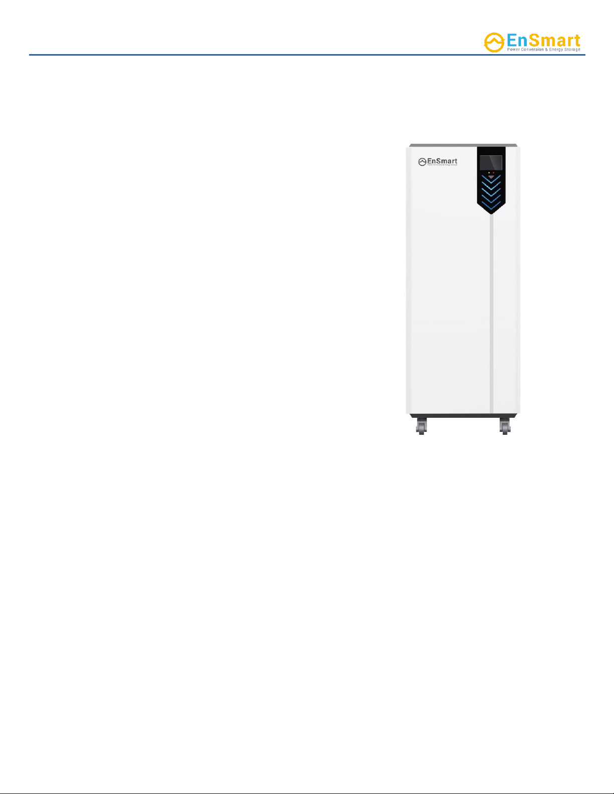
ENSMART ELV-F Series Battery utilizes most
environmentally LiFEPO4 cells, which eliminates operating
temperature constraints, and the risk of thermal runaway
and fire. The built-in smart Battery Management System
(BMS) integrates multilevel safety concepts: Overcharge
and Over-discharge Protection; Temperature Observation;
OverloadMonitor,and Cell balancing.
ENSMART ELV-F Series Battery are manufactured according
to UL1973&UL9540A&IEC62619. Its materials meet the
flame-retardant requirements. And theBMS is designed
with redundant protection.
It comes with a smart USB Logging function (with optional
USB flash disk) and supports WIFI platform Monitor. It
supports up to 20 units in parallel, so that composes a large
commercial Energy Storage System with 300~400kWh
energy.
This installation manual contains information concerning
important procedures and features of Lithium batteries.
Read all the instructions in this manual before installation,
operation, transportation, storage and maintenance.
Rev.1.0 _2022.10.10

User Manual
2 / 23
Content
1.
SAFETY ATTENTION................................................................................................................................................... 3
2.
TRANSPORTATION, HANDELING AND STORAGE...................................................................................................... 5
2.1
Transportation and Handling........................................................................................................................... 5
2.2
Storage............................................................................................................................................................. 5
2.3
Response to emergency situations................................................................................................................. 5
3.
PRODUCTINTRODUCTION........................................................................................................................................ 7
3.1
Product Name.................................................................................................................................................. 7
3.2
Technical data................................................................................................................................................... 7
3.3
Product pictures............................................................................................................................................... 8
4.
INSTALLATION........................................................................................................................................................... 9
4.1
Installation Preparation ................................................................................................................................... 9
4.2
Installation Steps............................................................................................................................................ 11
4.2.1
Mounting and securing the battery............................................................................................................ 11
4.2.2
Connecting the battery to the Charge Controller and/or Hybrid Inverter ................................................ 11
4.2.3
Using Communication Port......................................................................................................................... 12
4.2.4
Grounding................................................................................................................................................... 13
4.2.5
System Commission.................................................................................................................................... 13
4.2.6
Parallel Connection..................................................................................................................................... 13
4.3
Wire the battery cables ................................................................................................................................ 17
4.4
Final Connection of the Installation............................................................................................................... 18
4.5
Turn off the Unit............................................................................................................................................. 18
4.6
Cut off the Unit............................................................................................................................................... 18
5.
OPERATING ............................................................................................................................................................. 19
6.
DIAGNOSTICGUIDE................................................................................................................................................. 21
7.
TROUBLESHOOTING Guide..................................................................................................................................... 22
Contact US................................................................................................................................................................... 23

User Manual
3 / 23
1.
SAFETY ATTENTION
❖All types of breakdown of the product may lead to a leakage of electrolyte or
flammable gas.
❖During installation of the battery, the utility grid, solar input must be disconnected from
the Battery Pack wiring. Wiring must be carried out by qualified personnel. Battery Pack is
not user serviceable. High voltage or current is present in the device.The electronics inside
the Battery Pack are vulnerable to electrostatic discharge. Observe the following
precautions:
❖Risks of explosion
➢Do not subject the battery pack to strong impacts.
➢Do not crush or puncture the battery pack.
➢Do not dispose of the battery pack in a fire.
❖Risks of fire
➢Do not expose the battery pack to temperatures in excess of 122 ℉(50℃).
➢Do not place the battery pack near a heat source such as a fireplace.
➢Do not expose the battery pack to direct sunlight.
➢Do not allow the battery connectors to touch conductive objects such as wires.
❖Risks of electric shock
➢Do not disassemble the battery pack
➢Do not touch the battery pack with wet hands
➢Do not expose the battery pack to moisture or liquids
➢Keep the battery pack away from children and animals.
❖Risks of damage to the battery pack
➢Do not allow the battery pack to come into contact with liquids.
➢Do not subject the battery pack to high pressures.
➢Do not place any objects on top of the battery pack.
The Lithium Batteries must always be installed with a charge controller and the appropriate
settings to protect the batteries from open PV voltage and other highvoltage charging sources.
The Battery Management System (BMS) alone will not protect the batteries from these extreme
electrical phenomena. Failure to adhere touser manual will void the Warranty.

User Manual
4 / 23
Most batteries pose some risk of shock or sparking during the installation and initial wiringand
connection process. Wearing insulated gloves, clothing and footwear and using electrically insulated
tools are required when working with Lithium Batteries. Cover, restrain or remove jewelry or conductive
objects (metal bracelets, rings, belt buckles, metal snaps, zippers, etc.) when working with any electrical
or mechanical device. Cover or restrain long hair and loose clothing when working with any electrical or
mechanical device.
CAUTION!
➢Verify polarity at all connections before energizing the system. Reverse polarity at the battery
terminals will void the Warranty and destroy the batteries. Do not short circuit the batteries.
➢Do not combine this type of Lithium Batteries with others.
➢Do not disassemble or modify the battery. If the battery housing is damaged, do nottouch
exposed contents.

User Manual
5 / 23
2.
TRANSPORTATION, HANDELING AND STORAGE
2.1
Transportation and Handling
Do not knock, drop, puncture, or crush the battery;
Do not expose battery to flames, incinerate or direct sunlight;
Do not open battery enclosure or disassemble the battery;
Do not lift battery by the terminal cables;
Do not vibrate battery;
Do not expose battery to water or other fluids;
Do not expose battery to open flame;
Do not place the product nearby highly flammable materials, it may lead to fire or explosion in caseof
accident;
Move batteries in the required direction. Do not place a battery upside down or tilt it;
A ventilated area is strongly recommended for handling the product.
2.2
Storage
Do not expose battery to high temperatures and direct sunlight under;
Store at cool and dry place. Storage Temperature (Min. /Max.): 41°F/5°C
–
95°F/35°C. Relative
Humidity (Min./Max.): 5%~75% RH;
Do not store in greenhouses and storage areas for hay, straw, chaff, animal feed, fertilizers,
vegetables or fruit products;
Do not store in a high temperature and humidity environment;
Store the product on a flat surface;
Store the product out of reach of children and animals;
Store the product where it should be minimal dust and dirt in the area;
Systems should be put into storage at 60% SOC and checked monthly to ensure the system SOC does not fall
below 20%. At 20% SOC the battery will self-discharge in approximately 2 months. Also check the voltage
every 3 months and recycle every 6 months if the battery is not use for long time.
2.3
Response to emergency situations
The battery pack comprises multiple batteries that are designed to prevent hazards resulting fromfailures.
However, ENSMART cannot guarantee their absolute safety.

User Manual
6 / 23
❖Leaking Batteries
If the battery pack leaks electrolyte, avoid contact with the leaking liquid or gas. If one isexposed
to the leaked substance, immediately perform the actions described below:
➢Inhalation: Evacuate the contaminated area and seek medical attention.
➢Contact with eyes: Rinse eyes with flowing water for 15 minutes and seek medical
attention.
➢Contact with skin: Wash the affected area thoroughly with soap and water, and seekmedical
attention.
➢Ingestion: Induce vomiting, and seek medical attention.
❖Fire
In case of fires, make sure that the extinguisher is available near the battery pack. Ifpossible, move
the battery pack to a safe area before it catches fire.
Note: Fire extinguisher
➢Water, carbon dioxide, dry chemical powder and foam are the most effective means to
extinguish a Lithium Ferrous Phosphate (LFP) battery fire.
➢Use ABC Fire extinguisher, if the fire is not from battery and not spread to it yet.

User Manual
7 / 23
3.
PRODUCTINTRODUCTION
3.1
Product Name
ELV-F 51 XXX A-TB-00
3.2
Technical data
1. Label changes/software parameters
2. Stands for ENSMART
3. Version iteration updates material numbers (sorted alphabetically)
4. Nominal Capacity XXXAh
5. Nominal Voltage 51.2V
6. Cabinet -mounted
7. Residential Storage
Items
ELV-F51300
ELV-F51400
Total Energy
15.36kWh
20.0 kWh
Usable Energy
14.7 kWh
19.2 kWh
Recommend Charge Current
90A
120A
Max. Charge Current (Continuous)
150A
180A
Max. Discharge Current Continuous)
180A
180A
Nominal Capacity
300 Ah
400Ah
Nominal Voltage
51.2 V
Charging Temperature
0℃~45℃(32~113F)
Discharging Temperature
-20℃~60℃(-4~140F)
Dimension [W*D*H]
498*408*1234.5mm
Weight
~200kg
~240kg
Enclosure Protection Rating
IP55 (indoor unit)
Scalability
Up to 20units
High Current Circuit Breaker
250 A
Battery Efficiency
>98%
Self-discharge rate (Sleep mode)
Capacity:≤3%/month;≤20%/years

User Manual
8 / 23
3.3
Product pictures
➢Product dimension (Unit:mm):
➢LCD:
LCD can display Voltage, Residual Energy, Power, SOC, Cycles, Temperature. User also canbrowse battery
factory information, and select inverter protocol, battery parallel Address and Temperature unit.
Note:
User can click "Temperature unit" on the LCD screen to switch the temperature unit.

User Manual
9 / 23
4. INSTALLATION
Safe and reliable installation requires trained and certified technicians. The following discussion of Battery
configurations is a basic primer. Due to the variety of systems and components in the field, all possible scenarios
are not covered. This is not the purpose of this section of the manual. Refer to professional installers regarding
your system and its components and specifications. We encourage you or your installer to contact us with
any specific questions for technical support. We arecommitted to working with you and your installation team
to achieve a safe, reliable storage system that will provide years of maintenance free service.
Lithium Batteries are designed for parallel operation only. Do not design for seriesconnection for
increased voltage. Series connection of this product can result in damage to Lithium Batteries and
will void warranty!
4.1
Installation Preparation
1)
Environment Requirement
Application scenarios
Residential & commercial energy storage
systems
Operating Environment
Indoor and place away from strong
electromagnetic radiation
Recommended salt spray
An area 2km from the coast
Ambient Temperature
-10~40℃(14~104℉)
IP grade
IP55
Storage Temperature
Short time(≤1month): -20~45℃(-4~110℉)Long
time (≥1month): 5~35℃(41~95℉)
Operating Humidity
0 ~ 85%
Install Altitude
≤4000m
Case Ground requirement
Use at least 6mm² copper wire with the
resister ≤1Ω.
2)
Tools & Materials
The following insulated tools and materials are required:
➢Positive and negative battery cables. We recommend copper cables AWG 3/0. The battery power cables
are not included. Please refer to the published Battery Cable Sizing Chart for the proper size, based on
your system specification.
➢Positive and Negative Terminal luge recommendation: M10*1.5 (diameter: 10mm or 3/8in).
➢Screwdriver.

User Manual
10 / 23
➢RJ45 cable.
➢Wall Mount hangers.
➢OHSA(Occupational Health and Safety Administration) approved personal protective equipment
Insulated gloves
Safety Glasses
Safety Shoes
3)
Check the packing list
Check the battery package, type, quantity, appearance and other components.
Parts
QTY
Phot
o
Battery parallel communication
cable_RJ45_ RJ45
1pcs
Expanding screw M8*60, fix
rack on the floor
4pcs
Inverter communication
cable_RJ45_Gray*
Optionnal
L-shaped support foot
2pcs
* Note: Usually user equip inverters of different brands, which need prepare different kinds of
communication cable. The dealer can inform us the inverter brand which this battery support, such as
Schneider, Deye, Sol-ark, Megarevo, SMA, Victron, Growatt. Before installation, connect the matching
inverter with thedealer to avoid the mismatch of the inverter in the installation process.
Check if there is any damage on the battery box.
Check the battery terminals and connections to make sure they are clean, free of dirt,fluids
and corrosion.
All battery cables and their connections should be tight, intact, and NOT broken or
frayed.
Check torque on terminal bolts.
Replace any damaged batteries and cables.
IMPORTANT NOTE: Please inform us of any problems within 7 days of receipt ofgoods. Otherwise,
we deem that clients have no objection to the goods.

User Manual
11 / 23
4)
Installation Location
The battery pack must be installed indoors. Make sure that the installation location meets thefollowing
conditions:
The area is completely waterproof.
The floor is flat and level (Inclination < 15°).
There are no flammable or explosive materials.
The optimal ambient temperature is within the range from 59 ℉(15℃)
to 95 ℉(35℃).
The temperature and humidity are maintained at a constant level.
There is minimal dust and dirt in the area.
IMPORTANTNOTE: The ambient temperature exceeds the operating range, the batterypack may stop
operating to protect itself. Frequent exposure to harsh temperatures
may deteriorate the performance and life of the battery pack.
4.2
Installation Steps
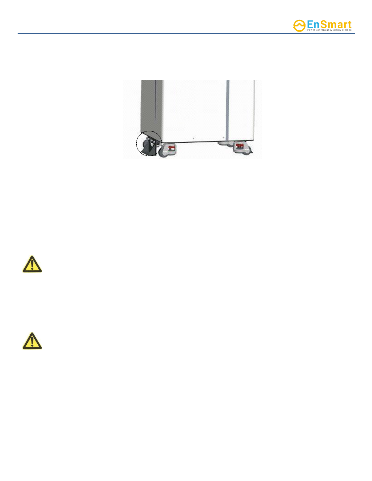
4.2.1
Mounting and securing the battery
The ELV-F Series Battery is designed to stand on the floor with 4 wheels on the bottom. If desired to
strengthen Anti earthquake ability, the rack should be fixed on floor with expanding screw and L- shaped
holder prepared in wooden case. We recommend putting the batteries on platform to avoid flooding. Please
refer to the Lithium Battery Data Sheet for weight and dimension. Lock the wheels on the battery pack.
4.2.2
Connecting the battery to the Charge Controller and/or Hybrid Inverter
The battery terminals are positioned under the top cover. Please make sure the breaker on theleft side
of rack is in the OFF position. Please install the positive cable first and the negative
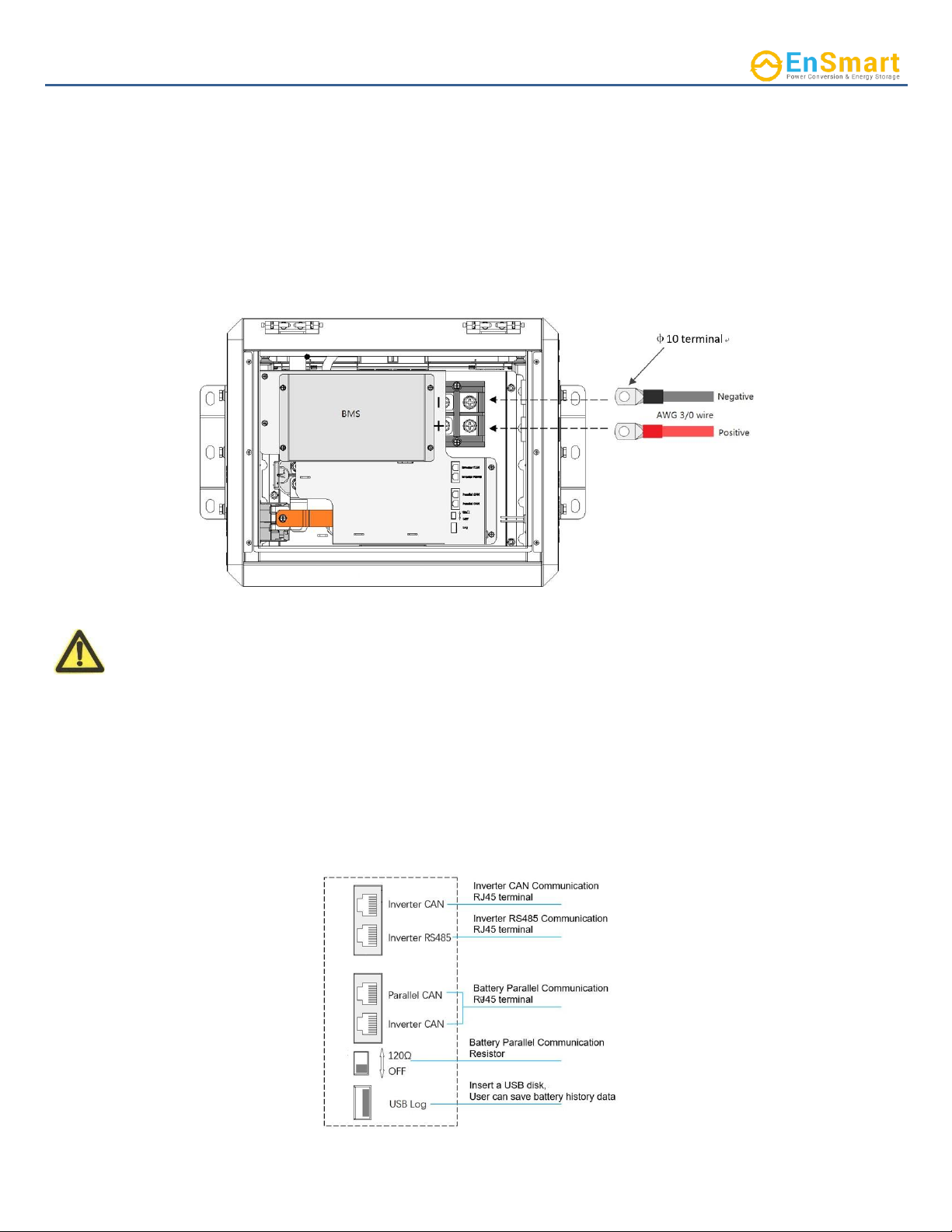
User Manual
12 / 23
cable second. Please do not cross the positive and negative terminals; also, ensure the terminals
are not
connected to any metal mounting, fixture, or body part. Recommended terminal torquerange is 10.0 –
19.1 N·m (7.4
–
14.1 ft.lb)
The Lithium Batteries are equipped with two M10 threaded terminals with a lock washer and nut. 10mm
ring terminals along with proper size wiring cables are required to connect battery to inverter/charger.
Positive use red wire and connect to “+” electrode; negative use black wire and connect to “-”electrode.
Do not reverse polarity to void warranty.
Top View
NOTE! Withoutexception,productsexperiencingterminalburnoutwillnotcoveredunderthewarranty.
4.2.3
Using Communication Port
ELV-F Series Battery has a self-managed Battery Management System (BMS). The Communication board
has five ports which are designed to support Inverter RS 485 and CAN communication, battery parallel
communication (see section 4.5.6.) and USB Logging. And Usercan set the battery Parallel CAN port
terminator by Small toggle switch
User Manual
13 / 23
4.2.4
Grounding
Grounding the battery, if necessary. ENSMART ELV-F series has 1 grounding holes on the bottomof battery
case.
4.2.5
System Commission
If you only install single ELV-F Series Battery, please follow the below steps to start up.
1)
Check system connection cables for correct polarity.
2)
Put the battery’s breaker on the “ON” position.
3)
Put inverter breaker in the “ON” position.
4)
Push the power button on the front of the unit for 3 seconds to turn on the battery LCD
display.
If you install multiple inverters with one or more ELV-F Series Battery, please turn the firstInverter on
by following the above mentioned steps, then power up the remaining inverters.
4.2.6
Parallel Connection
Lithium Batteries with the same capacity may be connected in parallel up to 20 units with high stability,
efficiency and overall quality. A qualified installer should understand this and must adhere to the
industry standard and published electrical guidelines.
CAUTION! Lithium Batteries are designed for parallel operation only. Do not connect inseries for
increased voltage. Series connection can result in damage to Lithium Batteries and will void
warranty!
The Storage Capacity and total available Amperage are increased by the parallel connection. The
following illustration shows how to connect multiple batteries in parallel. Please note the overall
Voltage is not changed. The available Amperage from the system has been accumulated.

User Manual
14 / 23
CAUTION! For parallel connecting: Maintain identical wire length and wire construction from each
Battery terminal to the common bus. If you parallel more than 4 units, a batterycombiner is highly
recommended.
System wire block diagram
Note: Battery address Numbers are set by LCD.
Please follow the procedure to parallel ELV-F Series batteries
1)
Prepare communication cable. Each unit comes with 2pcs RJ45 cable (One for inter- battery Parallel
CAN port, the other for communication with inverter). If the cable is missing, please make sure the
cable you purchase on the market meets the following standards. Please note that a standard RS485
cable is used.
Note: Inverter CAN and RS485 are optional, and just be used one of them depending oninverter
communication port.

User Manual
15 / 23
BATTERY & INVERTER
CAN Port
BATTERY & INVERTER
RS485 Port
INTER-BATTERY
Parallel CAN port
2)
Confirm the Battery DC breaker is in the “OFF” position.
3)
Wire each battery’s Power bus to Inverter. And wire inverter’s cable to PV, Grid and Load.
4)
Use the RJ45 cables to connect the batteries’ Parallel CAN port, as illustrated in the chart below. Ensure
communication matching resistor of two terminal (Unit 1 & Unit N) is set as 120Ω(Dial left) ,others is
set as OFF.
5)
Press the button on the front of each battery for 3+seconds one by one, until all
batteries wake up.
6)
Touch the batteries’ LCD to set Battery “Address setup” from 1 to N (Parallel number)as the
picture below.
Note: If used for single battery without parallel, must set “Address setup” as 0.
Pin No.
Definition
1
INVERTER_CANH
2
INVERTER_CANL
3
CANGND
4
NC
5
NC
6
NC
7
NC
8
NC
Pin No.
Definition
1
NC
2
NC
3
INVERTER_RS485A
4
NC
5
INVERTER_RS485B
6
RS485GND
7
NC
8
NC
Pin No.
Definition
1
BMS debug_CANH
2
BMS debug_CANL
3
CANGND
4
NC
5
NC
6
CANGND
7
Parallel_CANL
8
Parallel_CANH

User Manual
16 / 23
7)
Touch the LCD to set Inverter “Inverter Setup” as the following form.
Inverter Setup
Support Inverter Protocol
1
Deye CANbus,500kbps
2
SMA CANbus, 500kbps
3
Reserved
4
Victron CAN, 250kbps
5
Schneider Modbus, 19200bps
6
Solark/Megarevo CANBus,
500kbps
7
Voltronic Modbus, 9600bps
8
Growwat Modbus,9600bps
9
Reserved
10
Reserved
8)
Use RJ45 cable to connect the inverter CAN or RS485 port of master battery (whichBattery ID set
as 1) to inverter communication port.
9)
Turn ON inverter’s breaker, then turn ON all batteries’ DC breaker, and then press the button ofmaster
battery (Battery ID 1) for 6+ seconds to turn off, at last press master battery’s button for 3+ seconds to
start automatically PARALLEL PROCESS as below:
a)
Master battery requests the lowest voltage battery of the whole bank to pre-charge and turnon
relay, and request charge current from inverter.
b)
As the battery voltage increase by inverter, other battery join in to parallel one by one.
c)
After all normal batteries complete parallel, the PARALLEL PROCESS end up, and recovernormal
request from inverter.

User Manual
17 / 23
4.3
Wire the battery cables
CAUTION! For parallel connecting: Maintain identical wire lengths and wire gauge fromeach
Battery terminal to the common bus.
CAUTION! For connecting multiple units: Maintain the recommended distance among battery
units’s side or wall- at least 12inches (300mm). Keep battery unit’ front at lease 20inches
(500mm) away from wall, battery unit’ rear at lease 4inches (100mm) away fromwall. And keep
battery unit’ side at lease 20inches (500mm) away from Inverter or ceiling.
1.
Connect the positive and negative common bus to the inverter.
2.
Please put battery breaker into “ON” Position
3.
Please put inverter breaker into “ON” Position
CAUTION! If Paralleling the ELV-F Series Battery without connecting them via RJ45 cable(s),please
makesurethe voltage differencebetweenthehighestvoltageandlowestvoltage does not exceed 1.0
volts. A large current flow from the higher voltage battery to the lower voltage batterycould
potentially damage one or both batteries.
Resulting damage tothe battery will void the warranty.
CAUTION! Verify polarity at all connections with a standard voltmeter before energizingthe system.
Reverse polarity at the battery terminals will void the Warranty and destroythe batteries. Do not
short circuit the batteries.

User Manual
18 / 23
KEY POINTS SUMMARY:
1.
Each Lithium Battery contains circuitry that protects the Lithium Ferro Phosphate cells from overcharging,
over-discharging, and excessive load amperage. If the values specified are exceeded, the battery will enter a
protective shut down state. In some cases, this may result in the need to re- initialize an inverter charger or
other equipment in the installation. In other cases, the inverter’s systemsettings may be saved within the
inverter memory storage and will not need to be reset. This is not an
absolute standard but is common among most inverter chargers. Check your inverter manufacturer
specifications.
2.
If the battery enters a self-protective mode, negligible voltage readings will be present until the unit is reset.
In some instances, after unused for long time, a charge might need to be manually applied to the energy storage
bank. Should this occur, please contact ENSMART for technical support. Lithium Batteries are designed to remain
robust and safe under most circumstances.
3.
Although each Lithium Battery contains circuitry that protects the Lithium Ferro Phosphate cellsfrom
overcharging, over-discharging and excessive load amperage, Lithium Batteries must alwaysbe installed with
a charge controller and the appropriate settings to protect the batteries from openPV and other high voltage
sources. Lithium Batteries alone will not protect from extreme electrical phenomena.
4.
GRID TIED SYSTEMS: Once the Lithium Battery has been installed, turn on the entire systemto test. Once
testing has been completed, please disconnect the batteries from the load center until your local Utility
Inspector is ready to turn on the entire system. The charge controllers and inverter monitoring systems can
drain the Lithium Batteries over an extended period when the entire system is not fully operational due to the
electrical draw of the system components.
5.
OFF GRID SYSTEMS: Do not connect the Lithium Batteries until the entire system is ready to turn on and is
fully operational.
4.4
Final Connection of the Installation
Final installation and operation guidelines will be dictated by your Electrician and Installer based on the
overall properties of and procedures for the equipment in your installation and any code requirements that
apply to your region. ENSMART technicians and sales staff are available to provide any additional information
on the Lithium Batteries as needed. Please be aware of the potential electrical hazards before interacting
with any and all electrical or mechanical devices. Please take all necessary safety precautions in your projects
and installations.
4.5
Turn off the Unit
If you need to turn off the unit, please push the button for about 6 seconds.
4.6
Cut off the Unit
Battery has a breaker accessory, which is connected to battery outputterminal, and
can cut off both two electrodes of battery.

User Manual
19 / 23
5.
OPERATING
➢Operating Environment
See “3.1 Technical Data” Table on page 5
➢Charging
Never attempt to charge a battery without first reviewing and understanding the instructions for thecharger
being used. Only use a ENSMART Approved Lithium Ferro Phosphate (LFP) charger if ancillary charging is
required before installation, testing or troubleshooting. Failure to use aENSMART approved LFP charger will
damage the battery and void the warranty
CAUTION!
Please follow the following steps to use the charger to charge the battery:
•Connect the charger leads to the battery;
•Make sure that the charger lead, both at the charger and the battery side, connections aretight;
•Turn on the breaker of battery;
•Startup the battery by holding the power button of battery for about 3second;
•Turn the charger on.
CAUTION! Recommended charging current is 120A, Max. 200A (Please follow thespecification on
Lithium Battery Datasheet.)
➢Discharging
•Do not discharge battery below operating voltage.
•Do not discharge battery at rates greater than maximum continuous current.
•Do not operate in conditionsthat will exceed the internal operating temperaturesof the battery.
➢Parameter set up guide in Charger/Inverter
Before commissioning the energy storage system, the appropriate controller and inverter settings must be
programmed per the manufacturer’s recommendations. Consult the manufacturer’s manuals and/or
access technical support (Schneider, Sol-Ark, Victron, SMA, Growatt, Deye).
Although Lithium batteries can perform at very high rates and depths of discharge within a very wide
temperature range, in order to achieve extended life cycles and to comply with the Warranty, the following
guidelines should be followed:
This manual suits for next models
2
Table of contents
Popular Batteries Pack manuals by other brands


Anker
Anker Prime quick start guide

AmazonBasics
AmazonBasics B00LRK8EVO manual

Comunello Automation
Comunello Automation AC51 Installation and user manual

EnerSys
EnerSys SuperSafe OPzV Installation, operation and maintenance manual

Wagan
Wagan Power Dome NX 2 user manual

Stryker
Stryker SmartLife 7212-000-000 Instructions for use


