Dyness PowerRack HV4 User manual

PowerRack HV4
User Manual

I
Content
Statement of Law.................................................................................................................................. 1
Safety Precautions............................................................................................................................... 2
Preface.....................................................................................................................................................3
1 Introduction........................................................................................................................................4
1.1 Brief Introduction..................................................................................................................... 4
1.2 Product Properties...................................................................................................................4
1.3 Product identity definition..................................................................................................... 4
2 Product Specification......................................................................................................................6
2.1 System Performance Parameter.......................................................................................... 6
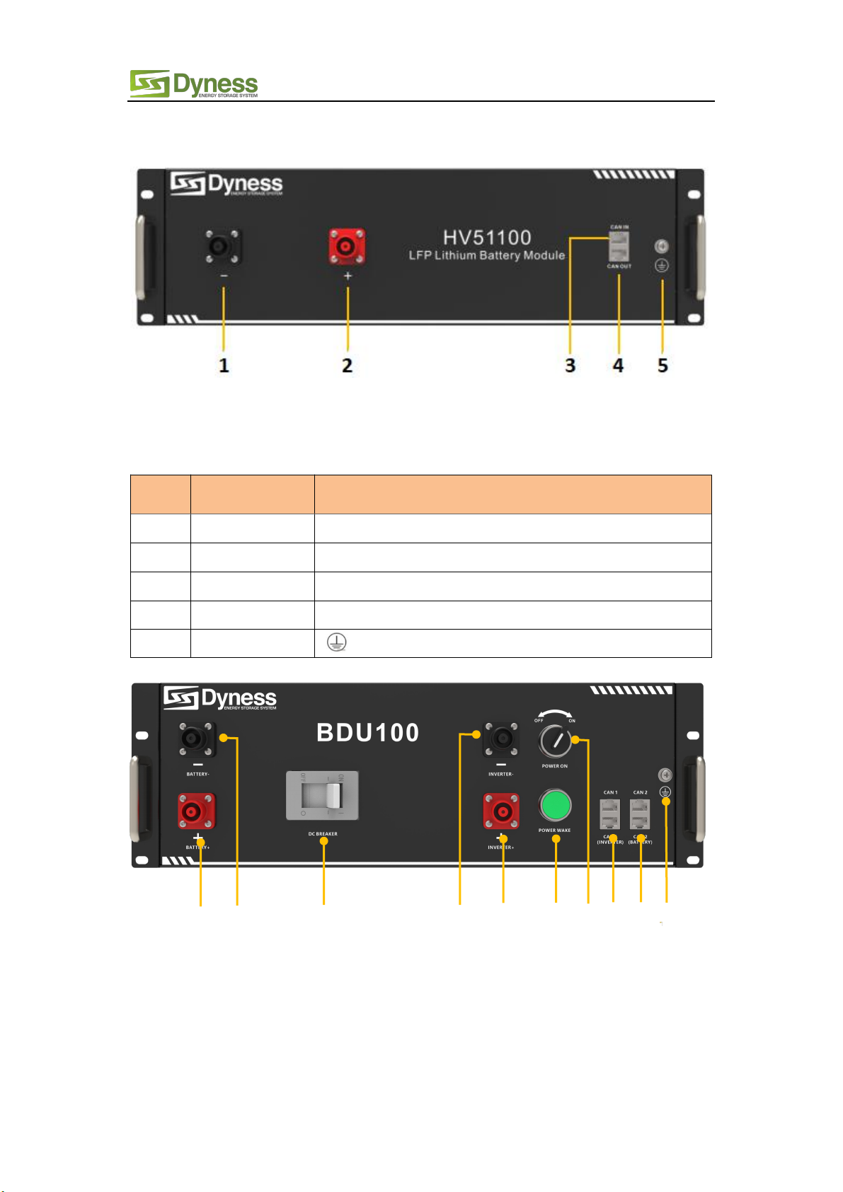
2.2 Battery Module..........................................................................................................................7
2.3 Interface Definition.................................................................................................................. 8
2.3.1 Communication port.........................................................................................................9
2.4 Battery Management System(BMS).................................................................................. 10
2.4.1 Voltage Protection......................................................................................................... 10
2.4.2 Current Protection......................................................................................................... 10
2.4.3 Temperature Protection............................................................................................... 10
3 Installation and Configuration.................................................................................................... 12
3.1 Preparation for installation..................................................................................................12
3.1.1 Environmental requirements...................................................................................... 12
3.1.2 Tools and data................................................................................................................ 12
3.1.3 Technical preparation...................................................................................................13
3.1.4 Unpacking inspection...................................................................................................13
3.1.5 Engineering coordination............................................................................................15
3.2 Equipment installation..........................................................................................................15
3.2.1 Installation preparation................................................................................................. 16
3.2.2 Mechanical installation..................................................................................................16
3.2.3 Electrical installation.................................................................................................... 18
3.2.4 Battery system self-test............................................................................................... 19
3.2.5 Shut down the system.................................................................................................. 19
3.2.6 Connecting inverter........................................................................................................20
3.2.7 Register on the website after installation............................................................... 21
4 Maintenance.................................................................................................................................... 22
4.1 Trouble shooting....................................................................................................................22
4.2 Replacement of main component......................................................................................22
4.2.1 Replacement of Battery Controller (BDU)..................................................................... 22
4.3 Battery Maintenance.............................................................................................................. 23
4.3.1 Voltage Inspection:.........................................................................................................23
4.3.2 Voltage Inspection:.........................................................................................................23
5 Storage Recommendations.......................................................................................................... 23
6 Shipment............................................................................................................................................24

PowerRack HV4 User Manual
1
Statement of Law
Copyright of this document belongs to Daqin New Energy Tech (Taizhou) Co., Ltd.
No part of this documentation maybe excerpted, reproduced, translated,
annotated or duplicated in any form or by any means without the prior
written authorization of Daqin New Energy Tech (Taizhou) Co., Ltd. All Rights Reserved.
This product complies with the design requirements of environmental protection and
personal safety. The storage, use and disposal of the products shall be carried out in
accordance with the product manual, relevant contract or relevant laws and regulations.
Customer can check the related information on the website of Daqin New Energy Tech
(Taizhou) Co., Ltd when the product or technology is updated. Web URL:
http://www.dyness-tech.com.cn
Please note that the product can be modified without prior notification.
Manual Version: V1.0
Revision History
Revision NO.
Revision Date
Revision Reason
1.0
2021.09.06
First Published

PowerRack HV4 User Manual
2
Safety Precautions
Warning
Please do not put the battery into water or fire, in case of explosion or any other
situation that might endanger your life.
Please connect wires properly while installation, do not reverse connect.
To avoid short circuit, please do not connect positive and negative poles with
conductor on the same device.
Please avoid any form of damage to battery, especially stab, hit, trample or strike.
Please shut off the power completely when removing the device or reconnecting
wires during the daily use or it could cause the danger of electric shock.
Please use dry powder extinguisher to put out the flame when encountering a fire
hazard, liquid extinguisher could result in the risk of explosion.
For your safety, please do not arbitrarily dismantle any component in any
circumstances. The maintenance must be implemented by authorized technical
personnel or our company’s technical support. Device breakdown due to
unauthorized operation will not be covered under warranty.
Caution
The products have been strictly checked before shipment. Please contact us if you
find any abnormal phenomena such as device outer case bulging.
In order to ensure safety and normal use of the product, the equipment should be
grounded properly before use.
To assure the product normal operation, please make sure parameters among the
relevant device are compatible and matched.
Please do not mixed-use batteries from different manufacturers, different types and
models, as well as old and new together.
Ambient and storage method could impact the product life span, please comply with
the operation environment instruction to ensure device works in proper condition.
For long-term storage, the battery should be recharged once every 3 months, and the
amount of electric charge shall exceed 80% of the rated capacity.
Please charge the battery in 18 hours after it fully discharged or over-discharging
protection mode is activated.
Formula of theoretical standby time: T=C/I (T is standby time, C is battery capacity, I
is total current of all loads).

PowerRack HV4 User Manual
3
Preface
Manual declaration
PowerRack HV4 battery energy storage system can provide energy storage function for
photovoltaic power generation users. Our product can store extra electricity into battery
from photovoltaic power generation system in daytime and supply stable power to user’s
equipment as power backup at nighttime or any time when needed. It can improve the
efficiency of photovoltaic power generation and increase the electric power efficiency
by peak load shifting.
This user manual details the basic structure, parameters, basic procedures and methods
of installation and operation and maintenance of the equipment.

PowerRack HV4 User Manual
4
1 Introduction
1.1 Brief Introduction
HV51100 lithium iron phosphate battery system is a high voltage battery system
unit, customers can choose a certain number of HV51100 according to their needs,
by connecting series to form a PowerRack HV4, to meet the user's long-term
power supply needs. The product is especially suitable for application scene of
high power, limited installation space, long power backup time and long service life.
1.2 Product Properties
HV51100 energy storage product’s positive electrode materials are lithium iron
phosphate, battery cells are managed effectively by BMS with better performance,
the system’s features as below:
Comply with European ROHS, Certified SGS, employ non-toxic, non-pollution
environment-friendly battery.
Anode materials are lithium iron phosphate (LiFePO4), safer with longer life
span.
Carries battery management system with better performance, possesses
protection function like over-discharge, over-charge, over-current, abnormal
temperature.
Self-management on charging and discharging, Single core balancing function.
Intelligent design configures integrated inspection module.
Flexible configurations allow parallel of multi battery for longer standby time.
Self-ventilation with lower system noise.
Less battery self-discharge, then recharging period can be up to 10 months
during the storage.
No memory effect so that battery can be charged and discharged shallowly.
With wide range of temperature for working environment, -20 ℃~ +55 ℃,
circulation span and discharging performance are well under high temperature.
Less volume, lighter weight.
1.3 Product identity definition
Battery Energy Storage System nameplate
Figure1-1 nameplate of BDU-1 Figure1-2 nameplate of BDU-2

PowerRack HV4 User Manual
5
Figure1-3 nameplate of HV51100
Battery voltage is higher than safe voltage, direct
contact with electric shock hazard.
Be careful with your actions and be aware of the
dangers.
Read the user manual before using.
The scrapped battery cannot be put into the
garbage can and must be professionally
recycled.
After the battery life is terminated, the battery can
continue to be used after it recycled by the
professional recycling organization and do not
discard it at will.

PowerRack HV4 User Manual
6
2 Product Specification
2.1 System Performance Parameter
Table 2-1 The parameter of PowerRack HV4 system-1
Item
PowerRack
HV4 -20
PowerRack
HV4 -25
PowerRack
HV4 -30
PowerRack
HV4 -35
Module Type
LFP
LFP
LFP
LFP
Nominal Voltage(V)
204.8V
256V
307.2V
358.4V
Work Voltage Range(V)
179.2~230.4
224~288
268.8~345.6
313.6~403.2
Module configuration
4 Series
5 Series
6 Series
7 Series
Nominal Energy(kWh)
20.48
25.6
30.72
35.84
Nominal Power(kW)
12.288
15.36
18.432
21.504
Max Power(kW)
20.48
25.6
30.72
35.84
Charging Current(A)
50
50
50
50
Discharge Current(A)
50
50
50
50
Dimension(mm)
601*610*1422
601*610*1422
601*610*1422
601*610*1422
Weight(kg)
237
290.5
344
397.5
Battery Module Name
HV51100
HV51100
HV51100
HV51100
Battery Module
Quantity(pcs)
4
5
6
7
Table 2-2 The parameter of PowerRack HV4 system-2
Item
PowerRack
HV4 -40
PowerRack
HV4 -46
PowerRack
HV4 -51
PowerRack
HV4 -56
Module Type
LFP
LFP
LFP
LFP
Nominal Voltage(V)
409.6V
460.8V
512V
563.2V
Work Voltage Range(V)
358.4~460.8
403.2~518.4
448~576
492.8~633.6
Module configuration
8 Series
9 Series
10 Series
11 Series
Nominal Energy(kWh)
40.96
46.08
51.2
56.32
Nominal Power(kW)
24.576
27.648
30.72
33.792
Max Power(kW)
40.96
46.08
51.2
56.32
Charging Current(A)
50
50
50
50
Discharge Current(A)
50
50
50
50
Dimension(mm)
601*610*2062
601*610*2062
601*610*2062
601*610*2062
Weight(kg)
486
539.5
593
646.5
Battery Module Name
HV51100
HV51100
HV51100
HV51100
Battery Module
Quantity(pcs)
8
9
10
11

PowerRack HV4 User Manual
7
Figure2-1 PowerRack HV4-56
2.2 Battery Module
Table 2-3 Product parameter
Module Name
HV51100
Cell Technology
Li-ion(LFP)
Battery Module Capacity (kWh)
5.12
Battery Module Voltage (Vdc)
51.2
Battery Module Capacity (Ah)
100
Battery Module Charge Voltage (Vdc)
57.6
Battery Module Charge Current (Normal) [A]
50
Battery Module Discharge Current (Normal) [A]
50
Dimension(W*D*H, mm)
481*535*140
Communication
CAN
Pollution Degree (PD)
I
IP Grade
IP20
Weight(kg)
43.5

PowerRack HV4 User Manual
8
2.3 Interface Definition
This section elaborates the interface functions of the front interface of the device.
Figure2-2 The sketch of interface.
Table 2-4 Interface Definition
Item
Name
Definition
1
Negative socket
Battery output or Serial anode cable
2
Positive socket
Battery output or Serial anode cable
3
CAN IN
RJ45 port, connect to former module or BDU
4
CAN OUT
RJ45 port, connect to next module or BDU
5
Grounding
Shell ground connection
Figure2-3 The sketch of interface.
7
5
1
2
6
3
4
8
9
10

PowerRack HV4 User Manual
9
Table 2-5 Interface Definition
Item
Name
Definition
1
Positive socket
Battery input cable
2
Negative socket
Battery input cable
3
DC Breaker
The master switch of the battery system ,you must
switch on it before switching on power on & power wake
switch; Short circuit protection.
4
Negative socket
Battery output cable
5
Positive socket
Battery output cable
6
Power Wake
Button
Long press this button to start the battery system
7
Power On
switch
Turn on the switch to power the BMS system
8
CAN 1
RJ45 communication port between the battery system
and inverter
9
CAN 2
RJ45 communication port between battery module and
BDU
10
Grounding
Shell ground connection
2.3.1 Communication port
Figure 2-3 CAN interface definition
Table 2-6 BDU CAN1 Pin Definition
Foot position
Color
Definition
PIN1
Orange/white
Reserve
PIN2
Orange
XGND
PIN3
Green/white
Reserve
PIN4
Blue
CANH
PIN5
Blue/white
CANL
PIN6
Green
Reserve
PIN7
Brown/white
Reserve
PIN8
Brown
Reserve

PowerRack HV4 User Manual
10
Table 2-7 BDU CAN2 & Battery CAN Pin Definition
Foot position
Color
Definition
PIN1
Orange/white
WAKE
PIN2
Orange
24V+
PIN3
Green/white
24V+
PIN4
Blue
CANSH
PIN5
Blue/white
CANSL
PIN6
Green
24V-
PIN7
Brown/white
24V-
PIN8
Brown
CANSG
2.4 Battery Management System(BMS)
2.4.1 Voltage Protection
Low Voltage Protection in Discharging :
When any battery cell voltage or total voltage is lower than the rated protection value
during discharging, the over-discharging protection is activated. Then battery system
stops supplying power to the outside. When the voltage of each cell back to rated return
range, the protection is over.
Over Voltage Protection in Charging:
Battery will stops charging when total voltage or any battery cell voltage reaches the
rated protection value during charging stage. When total voltage or all cell back to rated
range, the protection is over.
2.4.2 Current Protection
Over Current Protection in Charging:
When the charge current is higher than the protection value, the system stops charging.
Protection is released after rated time delaying or charging current released.
Over Current Protection in Discharging:
When the discharge current is higher than the protection value, the system stops
discharging. Protection is released after rated time delaying or discharging current
released.
2.4.3 Temperature Protection
Low/Over temperature protection in charging:
When battery's temperature is beyond range of 0℃~+55℃during charging, temperature
protection is activated, device stops charging.
The protection is over when temperature back to rated working range.
Low/Over temperature protection in discharging:

PowerRack HV4 User Manual
11
When battery's temperature is beyond range of -20 ℃~+55 during discharging,
temperature protection is activated, device stops supplying power to the outside.
The protection is over when temperature back to rated working range..
Caution
Battery’s maximum discharging current should be more than load’s maximum working
current.

PowerRack HV4 User Manual
12
3 Installation and Configuration
3.1 Preparation for installation
Safety Requirement
This system can only be installed by personnel who have been trained in the power
supply system and have sufficient knowledge of the power system.
The safety regulations and local safety regulations listed below should always be
followed during the installation.
All circuits connected to this power system with an external voltage of less
than 48V must meet the SELV requirements defined in the IEC60950
standard.
If operating within the power system cabinet, make sure the power system is
not charged. Battery devices should also be switched off.
Distribution cable wiring should be reasonable and has the protective
measures to avoid touching these cables while operating power equipment.
when installing the battery system, must wear the protective items below:
The isolation gloves Safety goggles Safety shoes
Figure3-1
3.1.1 Environmental requirements
Working temperature: -10℃~ +55℃
Charging temperature range is 0℃~+55℃
Discharging temperature range is -10℃~+55℃
Storage temperature: -10℃~ +35℃
Relative humidity: 5% ~ 85%RH
Elevation: no more than 4000m
Operating environment: Indoor installation, sites avoid the sun and no wind, no
conductive dust and corrosive gas.
And the following conditions are met:
Installation location should be away from the sea to avoid brine and high humidity
environment.
The ground for product arrangement shall be flat and level.
There is no flammable explosive materials near to the installation site.
The optimal ambient temperature is 15℃~ 30℃
Keep away from dust and messy zones.
The installation site must be equipped with fire-extinguisher system for safety
purpose.
3.1.2 Tools and data
Hardware tool
Tools and meters that may be used are shown in table 3-1.

PowerRack HV4 User Manual
13
Table 3-1 Tool instrument
Name
Screwdriver(Slotted、Phillips)
Multimeter
Torque wrench
Clamp current meter
Diagonal pliers
Insulation tape
Pointed nose pliers
Temperature meter
Pliers to hold the wire
Anti-static bracelet
Stripping pliers
Cable tie
Electric drill
Tape measure
3.1.3 Technical preparation
Electrical interface check
Devices that can be connected directly to the battery can be user equipment,
power supplies, or other power supplies.
Confirm whether the user's PV power generation equipment, power supply or
other power supply equipment has a DC output interface, and measure
whether the DC power output voltage meets the voltage range requirements
in Table 2-1 and Table 2-2.
Confirm that the maximum discharge current capability of the DC power
interface of the user's photovoltaic power generation equipment, power
supply or other power supply equipment should be higher than the maximum
charging current of the products used in Table 2-1 and Table 2-2.
If the maximum discharge capacity of the DC power interface of the user's
photovoltaic power generation equipment is less than the maximum charging
current of the products used in Table 2-1 and Table 2-2, the DC power
interface of the user's photovoltaic power generation equipment shall have a
current limiting function to ensure the normal operation of the user’s
equipment.
Verify that the maximum operating current of the battery-powered user
equipment (inverter DC input) should be less than the maximum discharge
current of the products used in Table 2-1 and Table 2-2.
The security check
Firefighting equipment should be provided near the product, such as portable
dry powder fire extinguisher.
Automatic fire fighting system shall be provided for the case where
necessary.
No flammable, explosive and other dangerous materials are placed beside
the battery.
3.1.4 Unpacking inspection
When the equipment arrives at the installation site, loading and unloading
should be carried out according to the rules and regulations, to prevent from
being exposed to sun and rain.
Before unpacking, the total number of packages shall be indicated according
to the shipping list attached to each package, and the case shall be checked
for good condition.
In the process of unpacking, handle with care and protect the surface coating
of the object.
Open the package, the installation personnel should read the technical
documents, verify the list, according to the configuration table and packing
list, ensure objects are complete and intact, if the internal packing is
damaged, should be examined and recorded in detail.

PowerRack HV4 User Manual
14
Packing list of PowerRack HV4-56 is as follows:
Item
Specification
Quantity
Figure
Battery-
HV51100
51V/100Ah
480×535×133mm
11
BDU100
480×410×155mm
1
Power cable-
positive
Red
/35mm²/L3000mm
1
Power cable-
negative
Black
/35mm²/L3000mm
1
Serial cable
Orange
/35mm²/L215mm
10
Module cable-
positive
Orange
/35mm²/L215mm
1
Module cable-
negative
Orange
/35mm²/L2200mm
1
Communication
parallel cable
Black
/L350mm/Double
RJ45 plug
12
Communication
cable-to inverter
Black
/L3000mm
/Double
RJ45 plug
1

PowerRack HV4 User Manual
15
3.1.5 Engineering coordination
Attention should be paid to the following items before construction:
Power line specification.
The power line specification shall meet the requirements of maximum
discharge current for each product.
Mounting space and bearing capacity.
Make sure that the battery has enough room to install, and that the battery
rack and bracket have enough load capacity.
Wiring.
Make sure the power line and ground wire are reasonable. Not easy to short-
circuit, water and corrosion.
3.2 Equipment installation
Table 3-2 Installation steps
Step 1
Mechanical
installation
1.Battery placement position determination
2.Battery module installation
Communication
Bottom module
to BDU CAN2
IN
Black
/L2200mm
/Double
RJ45 plug
1
Ground wire
L3000mm,4mm²
1
User Manual
PowerRack HV4
User manual
1
Screw
Combination
screws
M6*14
60
CAN resistor
120Ω
1

PowerRack HV4 User Manual
16
3.BDU installation
Step3
Electrical
installation
1.Ground cable installation
2.Battery module serial cable installation
3.Connect the module cable-positive from the battery
“+” to the BDU “+”
4.Connect the module cable-negative from the battery
“-” to the BDU “-”
5. Connect the CAN 2 of the BDU with the CAN IN of
the battery module with the communication parallel
cable, then connect the CAN OUT of the previous
battery module with the CAN IN of the next battery
module in turn, and finally connect the CAN 2 of the
BDU with the communication parallel cable Connect
to the CAN OUT of the bottom battery module
Step4
Battery system
self-test
1.Turn the BDU ‘DC Breaker’ ON/OFF switch to the
"ON" state
2.Turn the ‘Power ON’ ON/OFF switch to the "ON"
state
3.Press ‘POWER WAKE’ button 3S to wake up
battery
4.Check the system output voltage and ‘POWER
WAKE’ led status
5. Shut down the system
Step5
Connecting
inverter
1.Connect total positive & total negative cable of the
battery system to the inverter
2.Connect the communication cable from the master
CAN 1 to the inverter
3.Close the DC breaker
4.Turn on the ‘Power ON’ switch , wake up system by
‘POWER WAKE’ button
5.Turn on the inverter and check the communication
between inverter and battery system
3.2.1 Installation preparation
1. Make sure the environment is meeting all technical requirements: “3.1.1”
2. Prepare equipment and tools for installation.
3. Confirm that the DC breaker is in the OFF state to ensure that it is no live
operation.
3.2.2 Mechanical installation
Installation method:
Figure3-2
1. Place the HV51100 unit on the
rack bracket as shown in the
figure and push the device into
the rack at the installation
position. (The rack structure in
the figure is for reference only)

PowerRack HV4 User Manual
17
Figure3-3
2. Secure the HV51100 unit to the
rack with a nut through the
mounting holes top on the
hanging ears of the HV51100
unit.
Figure3-4
Figure3-5
3. Insert the second one HV51100 in
to the rack.
4. Stack the required number
of battery and BDU as
described above, and use 4
screws to fix the battery and
BDU on the front bracket.
Shown as Figure3-5.

PowerRack HV4 User Manual
18
3.2.3 Electrical installation
Before connecting the power cables, use multimeter to measure cable continuity,
short circuit, confirm positive and negative, and accurately mark the cable labels.
Measuring methods:
Power cable check: select the buzzer mode of multimeter and detect the both
ends of the same color cable. If the buzzer calls, it means the cable is in good
condition.
Short circuit judgment: choose multimeter resistor file, probe the same end of
positive and negative pole, if the resistor shows infinity, means that the cable
is available.
After visual testing of power line connection, the positive and negative poles of
the battery shall be connected respectively to the positive and negative poles
of the opposite terminal.
It is better to add a circuit breaker between the inverter and the battery system.
Figure3-6
Power cable-
negative
Power cable-
positive
Module cable-
negative
Module cable-
positive
Communication
cable-to inverter
Communication
parallel cable
Inverter
Serial cable
Circuit
breaker
Table of contents
Other Dyness Batteries Pack manuals

Dyness
Dyness B4850 User manual

Dyness
Dyness Junior Box User manual

Dyness
Dyness Tower T Series User manual

Dyness
Dyness A48100 User manual

Dyness
Dyness B3 User manual

Dyness
Dyness WIFI-M01 User manual

Dyness
Dyness B48100 User manual

Dyness
Dyness POWERBOX Pro User manual

Dyness
Dyness POWERCUBE Series User manual

Dyness
Dyness DL5.0C User manual