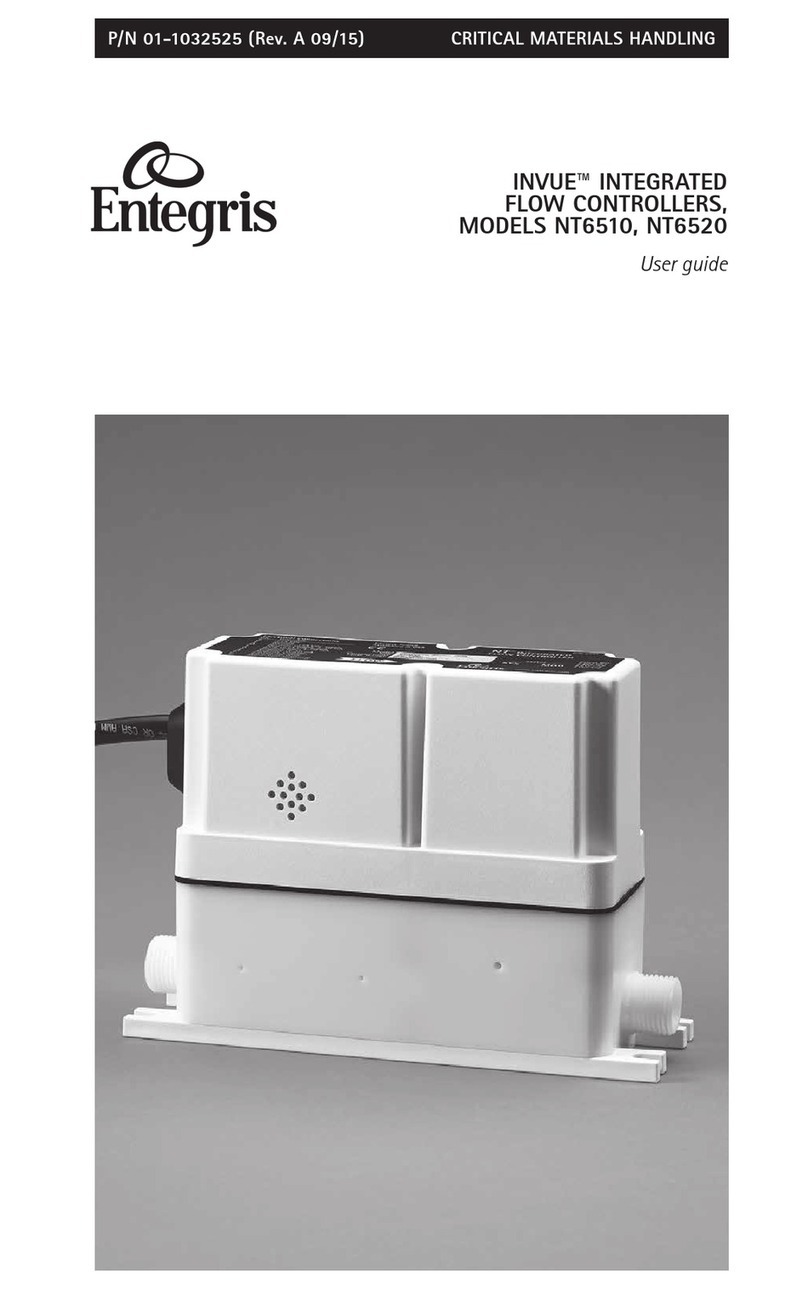
entegris InVue NT6510 User manual

P/N 01-1032525 | REV. B 02/19
InVue®Integrated Flow
Controllers, Models
NT6510, NT6520
User guide

INVUE INTEGRATED FLOW CONTROLLERS, MODELS NT6510, NT6520
1Entegris, Inc. | P/N 01-1032525 | Rev. B 02/19
Table of Contents
Introduction .................................. 2
Identifying Nonstandard
Product Configurations ............ 2
Principle of Operation .............. 2
Factory Configured ................... 3
Continuous versus
Batch Control ............................. 3
Calibration Reference
Conditions ................................... 3
General Considerations .............. 4
Power Supply Requirements ... 4
Storage Temperature Range ... 4
Operating Ambient
Temperature Range .................. 4
Operating Process
Temperature Range .................. 4
Line Pressure .............................. 4
Pressure Drop.............................. 4
Dimensions ................................. 5
Installation .................................... 8
Provided Equipment ................. 8
Mounting Requirements .......... 9
Mechanical Installation .......... 10
Power Supply Requirements ... 11
Electrical Connections ........... 13
Wiring Diagrams ...................... 16
Optional Connections ............ 17
Setpoint Signal Setup .............. 18
Calibration Graphs .................. 19
Unit Operation ............................ 20
Operating Environment ........ 20
Performance ............................. 21
Operational Reliability ............ 22
Status and Alarming ................ 22
LED Status Codes .................... 23
Diagnostic Guide ........................ 24
Maintenance ............................... 27
Normal Operation ................... 27
Re-zero Function .................... 27
Reference .................................... 29
Physical Specifications .......... 29
Electrical Specifications ........ 29
Performance Specifications .... 29
Ordering Information ............... 30
Certifications ............................... 33
CE Compliance ........................ 33
Repair and Warranty Service ..... 33
Technical Support ...................... 33
For More Information ................ 34
Terms and Conditions of Sale .. 34
Limited Warranty ........................ 34

INVUE INTEGRATED FLOW CONTROLLERS, MODELS NT6510, NT6520
2P/N 01-1032525 | Rev. B 02/19 | Entegris, Inc.
Introduction
This manual is for use with a standard
InVue®Integrated Flow Controller,
Models NT6510 and NT6520. These
instruments have been designed for
use in high-purity fluid applications
within industries that need tightly
controlled chemical processes such
as the semiconductor, biomedical,
and solar cell industries. The wetted
parts are constructed with Modified
PTFE, PTFE, PFA, or other similar
high-purity inert materials.
WARNING! Attempting to install or
operate standard InVue Integrated
Flow Controllers without reviewing
the instructions contained in this
manual could result in personal
injury or equipment damage.
IDENTIFYING NONSTANDARD
PRODUCT CONFIGURATIONS
—
This User Guide applies to product
manufactured as the standard InVue
Integrated Flow Controller. Entegris
also manufactures nonstandard
product to meet the needs of specific
applications. Nonstandard product
may have dierent materials of
construction, accuracy specifications,
performance, and other specifications
that dierentiate the nonstandard
product from the standard oering.
NOTE: Nonstandard InVue Integrated
Flow Controllers may be identified
by the model number found on the
product label. Specifications for
nonstandard InVue Integrated Flow
Controllers are available by contacting
Entegris.
Nonstandard InVue Integrated Flow
Controllers, Model NT6510, are
identified with an “N" followed by
a number code.
For example, in part number
6510-T2-F03-B06-A-P7-U3-N02,
the “N02" designates the product
as a nonstandard product manu-
factured to certain specifications
designated under the “N02" code.
Nonstandard InVue Integrated Flow
Controllers, Model NT6520, are
identified with an “R" followed by
a number code.
For example, in part number
6520-T6-F03-B06-A-P7-U3-R02,
the “R02" designates the product
as a nonstandard product manufac-
tured to certain specifications
designated under the “R02" code.
Contact Entegris for assistance with
nonstandard product applications.
PRINCIPLE OF OPERATION
—
The user provides a setpoint signal
that corresponds to the desired
amount of flow. The standard InVue
Integrated Flow Controller compares
the setpoint to the actual flow signal
from the flow module. If the actual
flow is greater than the setpoint, the
unit closes the valve. If the actual
flow is less than the setpoint, the unit
opens the valve. The flow controller
does this in a precise manner until
the actual flow signal is equal to
the setpoint.

INVUE INTEGRATED FLOW CONTROLLERS, MODELS NT6510, NT6520
3Entegris, Inc. | P/N 01-1032525 | Rev. B 02/19
FACTORY CONFIGURED
—
The standard InVue Integrated Flow
Controller is pre-configured from the
factory for the flow range specified
by the user. The specified flow range
is found on the label of the unit. The
unit control algorithm uses pressure
and flow measurements to ensure
proper operation within specification.
CONTINUOUS VERSUS
BATCH CONTROL
—
The standard InVue Integrated Flow
Controller may be ordered as a con-
tinuous type controller or a batch
type controller.
The continuous controller type is
for applications requiring continuous
flow rate control, where the integral
valve module is never required to fully
close. Typically, another valve is used
in conjunction with the flow control-
ler to stop the liquid flow.
The batch controller type is for appli-
cations requiring flow rate control
where the integral valve module will
fully close between batch dispense
cycles. If total volume needs to be
controlled, an additional separate
totalizer device must be employed.
CALIBRATION REFERENCE
CONDITIONS
—
Unless otherwise noted, the specifi-
cations listed for the InVue Integra-
ted Flow Controller are referenced
under the following operating
conditions:
PARAMETER REFERENCE CONDITION
Process fluid Deionized water
Process
temperature
23°C ±3°C (73°F ±5°F)
Ambient
temperature
23°C ±3°C (73°F ±5°F)
Process
pressure
207 kPa (30 psig)
Supply voltage 24 VDC ±10%
Operation Re-zeroed
Power
Setpoint
Re-zero
Pressure signal
Flow signal
Alarm
InVue Integrated Flow Controller System Diagram
Sensor
measurement
Valve
control
Fluid
flow
Fluid
flow
InVue Integrated Flow Controller
control interface
Flow/valve module

INVUE INTEGRATED FLOW CONTROLLERS, MODELS NT6510, NT6520
4P/N 01-1032525 | Rev. B 02/19 | Entegris, Inc.
General Considerations
The following requirements and
specifications are briefly provided
here. Before installing and operating
the InVue Integrated Flow Controller,
see the Installation and Unit Opera-
tion sections of this user guide for
more detailed information.
NOTE: The flow controller has been
factory sealed. Do not attempt to
remove the cover of the unit. Any
attempt at removal of the unit cover
will void the warranty.
POWER SUPPLY REQUIREMENTS
—
The power supply range for the
flow controller is 24 VDC ±10%.
The power supply to the unit must
provide clean power and must be
used only to power similar measure-
ment-type devices.
STORAGE TEMPERATURE RANGE
—
The flow controller can withstand
storage temperatures between
-15°C–40°C (5°F–104°F) with no
permanent eect on the perfor-
mance of the device.
OPERATING AMBIENT
TEMPERATURE RANGE
—
The flow controller is designed to
operate in ambient temperature,
cleanroom environments. It is speci-
fied to operate at temperatures of
10°C–65°C (50°F–149°F).
OPERATING PROCESS
TEMPERATURE RANGE
—
The flow controller is designed to
operate in process temperatures of
10°C–65°C (50°F–149°F).
LINE PRESSURE
—
The system line pressure (measured
at the inlet of the unit) must be
69 kPa – 414 kPa (10 psig – 60 psig).
PRESSURE DROP
—
The flow rate is calculated using
Entegris' dierential pressure flow
technology. The minimum pressure
drop (inlet to outlet port dierential
pressure) required for the unit is
69 kPa (10 psig).

INVUE INTEGRATED FLOW CONTROLLERS, MODELS NT6510, NT6520
5Entegris, Inc. | P/N 01-1032525 | Rev. B 02/19
DIMENSIONS
—
NT6510
The following fitting size and flow range combinations are available
(Flaretek®, PrimeLock®, and Pillar®unless otherwise noted):
FITTING
SIZE
FLOW RANGE (ML/MIN)
TL
0–15
TT
0–25
T0
0–50
T1
0–125
T2
0–250
T3
0–500
T4
0–1250
1⁄4"Yes Yes Yes Yes Yes Yes Yes
3⁄8"Yes Yes Yes Yes Yes Yes Yes
1⁄2"—————Yes* Yes*
*Flaretek and PrimeLock only.
Please consult Entegris for custom flow range requirements.
INLET/OUTLET PORT
CONNECTION
DIMENSIONS
ABC
1⁄4" Flaretek tube fitting 118.1 mm (4.65") 17.0 mm (0.67") 187.5 mm (7.38")
3⁄8" Flaretek tube fitting 119.6 mm (4.71") 17.0 mm (0.67") 191.0 mm (7.52")
1⁄2" Flaretek tube fitting 119.6 mm (4.71") 17.0 mm (0.67") 195.1 mm (7.68")
1⁄4" PrimeLock tube fitting 118.1 mm (4.65") 17.0 mm (0.67") 177.8 mm (7.00")
3⁄8" PrimeLock tube fitting 119.6 mm (4.71") 17.0 mm (0.67") 177.8 mm (7.00")
1⁄2" PrimeLock tube fitting 119.6 mm (4.71") 17.0 mm (0.67") 182.4 mm (7.18")
1⁄4" Super 300 Pillar
tube fitting
118.1 mm (4.65") 17.0 mm (0.67") 159.3 mm (6.27")
3⁄8" Super 300 Pillar
tube fitting
119.6 mm (4.71") 17.0 mm (0.67") 167.1 mm (6.58")

INVUE INTEGRATED FLOW CONTROLLERS, MODELS NT6510, NT6520
6P/N 01-1032525 | Rev. B 02/19 | Entegris, Inc.
NT6520
The following fitting size and flow range combinations are available
(Flaretek, PrimeLock, and Pillar unless otherwise noted):
FITTING
SIZE
FLOW RANGE (L/MIN)
T5
0–2.5
T6
0–5
T7
0–10
T8
0–20
T9
0–40
3⁄8"Yes* Yes* ———
1⁄2"Yes** Yes** Yes — —
3⁄4"———Yes Yes
*Flaretek and Pillar only.
**Flaretek and PrimeLock only
Please consult Entegris for custom flow range requirements.
137.2 mm (5.40")
154.9 mm (6.10")
167.6 mm (6.60")
C
53.2 mm
(2.10")
39.4 mm
(1.55")
Top View
5.1 mm
(0.20")
A
Side View
B
End View

INVUE INTEGRATED FLOW CONTROLLERS, MODELS NT6510, NT6520
7Entegris, Inc. | P/N 01-1032525 | Rev. B 02/19
INLET/OUTLET PORT
CONNECTION
DIMENSIONS
ABC
3⁄8" Flaretek tube fitting 117.3 mm (4.62") 15.7 mm (0.62") 224.0 mm (8.82")
1⁄2" Flaretek tube fitting 120.9 mm (4.76") 18.3 mm (0.72") 228.0 mm (8.98")
3⁄4" Flaretek tube fitting 129.0 mm (5.08") 23.6 mm (0.93") 234.2 mm (9.22")
1⁄2" PrimeLock tube fitting 120.9 mm (4.76") 18.3 mm (0.72") 215.4 mm (8.48")
3⁄4" PrimeLock tube fitting 129.0 mm (5.08") 23.6 mm (0.93") 229.1 mm (9.02")
3⁄8" Super 300 Pillar
tube fitting
117.3 mm (4.62") 15.7 mm (0.62") 200.2 mm (7.88")
1⁄2" Super 300 Pillar
tube fitting
120.9 mm (4.76") 18.3 mm (0.72") 205.2 mm (8.08")
3⁄4" Super 300 Pillar
tube fitting
129.0 mm (5.08") 23.6 mm (0.93") 214.1 mm (8.43")
Top View
47 mm
(1.85")
187.5 mm (7.38")
170.2 mm (6.70")
200.2 mm (7.88")
7.1 mm
(0.28")
71.1 mm
(2.80")
C
B
A
Side View
End View

INVUE INTEGRATED FLOW CONTROLLERS, MODELS NT6510, NT6520
8P/N 01-1032525 | Rev. B 02/19 | Entegris, Inc.
Installation
PROVIDED EQUIPMENT
—
Verify:
Remove Unit from the Bag
NOTE: This unit has been assembled
and double-bagged under cleanroom
conditions. To maintain purity, only
open under cleanroom conditions.
CAUTION! Do not tighten the nuts that
protect the tube connections during
shipment. (See the Prepare Fluid Lines
section on page 10). Tightening these nuts
without the proper tubing installed may
damage the unit's tube connections.
Gloves

INVUE INTEGRATED FLOW CONTROLLERS, MODELS NT6510, NT6520
9Entegris, Inc. | P/N 01-1032525 | Rev. B 02/19
MOUNTING REQUIREMENTS
—
The flow controller may be mounted
in any orientation. The unit does not
require straight lengths of tubing at
the inlet or the outlet connection.
Mount the Unit
The flow controller and base bracket
assembly must be mounted to a solid
surface to ensure stability. Verify the
valve and the electrical cable are free
from mechanical stress from the
surrounding equipment.
NOTE: The flow controller requires
mounting in the direction of the
fluid flow.
#10 (M4)
Pan head
#10 (M4)
Flat washer
Recommended hardware

INVUE INTEGRATED FLOW CONTROLLERS, MODELS NT6510, NT6520
10 P/N 01-1032525 | Rev. B 02/19 | Entegris, Inc.
MECHANICAL INSTALLATION
—
The standard InVue Integrated Flow
Controller must be used with the
proper tubing size and fittings.
NOTE: For detailed Flaretek and
PrimeLock tube fitting assembly
instructions, visit www.entegris.com.
For detailed Super 300 Type Pillar tube
fitting assembly instructions, contact
Nippon Pillar Packaging Company, Ltd.
CAUTION! Over-tightening of
the nuts will result in damage
to the fitting.
Slide the nut onto the tube
Prepare Fluid Lines
Process fluid tube
Prepare each tube end
prior to installation
Connect Fluid Lines

INVUE INTEGRATED FLOW CONTROLLERS, MODELS NT6510, NT6520
11Entegris, Inc. | P/N 01-1032525 | Rev. B 02/19
Care should be taken when install-
ing the flow controller to avoid fluid
leaks. Do not use excessive torque or
subject the unit to high heat during
installation. The unit and base bracket
assembly must be mounted to a solid
surface to ensure stability. Verify the
body and the electrical cable are free
from mechanical stress from the
surrounding equipment.
POWER SUPPLY REQUIREMENTS
—
The power supply range for the flow
controller is 24 VDC ±10% regulated.
The power supply must provide con-
tinuous 1.0 ampere (nominal) service
for each flow controller installed. The
power supply requirements must be
met at the wire connections or con-
nector of the flow controller, not only
at the power supply itself.
The power supply to the unit must
provide clean power and must be
used only to power similar measure-
ment-type devices. The power supply
must not be used to power other
inductive loads, such as motors,
relays, or solenoids. These devices
may produce electrical transients
that may aect unit measurements.
An induced power spike, creating
an interruption in power greater than
10 milliseconds in duration, may
cause the unit to reset.
In addition to providing clean power,
the instrumentation signals and
power return lines must not be run
within the same conduit or cable
along with heavy current demands
from motors, charging capacitors, or
other inductive loads. This may cause
a voltage change within the instru-
mentation signal line, causing errone-
ous output readings from the flow
controller. Loss of power will not
cause the loss of any system para-
meters or calibration values.
Input Impedance of the
Voltage Setpoint
The input impedance of the voltage
setpoint is 37 kOhm.
Voltage Drop at the 4–20 mA
Setpoint Input
The 4–20 mA input will drop
<5 V at 20 mA. Input impedance
is <250 ohms.
Lift-o Voltage of the 4–20 mA
Output Loops
The minimum lift-o voltage of
the 4–20 mA output loops (flow,
pressure measurements) is 12 VDC.
The minimum lift-o voltage is
the voltage required at the unit for
proper operation. The maximum
load resistance for a 24 VDC supply
is 600 ohms and includes the
resistance of measurement devices
and the interconnecting cable.

INVUE INTEGRATED FLOW CONTROLLERS, MODELS NT6510, NT6520
12 P/N 01-1032525 | Rev. B 02/19 | Entegris, Inc.
Output Load Resistance Eects
Using a 24 VDC power supply, the
two 4–20 mA output loops (flow and
pressure) will experience no shift if
the load resistance is 0–600 ohms.
Reverse Polarity Protection
The flow controller is reverse polarity
protected; connecting the 24 VDC
power to any wires will not harm the
unit. To operate properly, the polarity
must be correct.
Over-voltage on any Wire (DC)
In the event of accidental application
of voltage greater than 24 VDC ±10%,
the flow controller will withstand
continuous 30 VDC on any wire
without compromising the unit.
Over-voltage on any Wire (AC)
The flow controller is not designed
to withstand the accidental applica-
tion of 110/220 VAC to any wire.
Application of AC voltage will
damage the unit.
Short Protection
The flow controller will not be damag-
ed or compromised in any way if any
combination of wires are shorted
together.
Circuit Protection
Fuse the three input power lines to
each individual InVue Integrated Flow
Controller. The three lines are:
• 2-Red/Pin R, +24 VDC (main
power, 1.0 Amp nominal)
• 3-Orange/Pin M, Flow output,
+24 VDC supply
• 4-Yellow/Pin T, Pressure output,
+24 VDC supply
Use a 2 Amp rated, time lag fuse. A
single fuse can be used for all three
input power lines combined, or in-
dividually, as preferred. Place the
fusing on the input power lines to
the unit at the equipment electrical
enclosure to ensure that both the
wiring to the unit and the unit itself
are protected from any over-current
condition. Best practice is to locate
the fuse away from the typical liquid
exposure or harmful vapor areas.
Locating it within the electrical
enclosure shared by the power
supply enables accessibility for
troubleshooting or replacement.
NOTE: Do not power down the unit
until the homing cycle is complete.

INVUE INTEGRATED FLOW CONTROLLERS, MODELS NT6510, NT6520
13Entegris, Inc. | P/N 01-1032525 | Rev. B 02/19
ELECTRICAL CONNECTIONS
—
Pigtail Electrical Cable
Units specified with a pigtail electrical
connection are manufactured with a
permanently attached cable.
Table 1 details the wire connections
for the flow controller type with pigtail
electrical cable.
Table 1: Wire connections – pigtail cable
WIRE COLOR MARKER NUMBER FUNCTION
Yellow 4Pressure output, +24 VDC supply
Brown 1Pressure output, 4–20 mA output
Orange 3Flow output, +24 VDC supply
Blue 5Flow output, 4–20 mA output
Green 9Re-zero input
Pink 11 Setpoint, voltage, 0–10 or 0–5 VDC
Gray 12 Setpoint, common
Tan 10 Setpoint, current, 4–20 mA
Black 8Ground (+24 VDC common)
Red 2+24 VDC
Violet 6Factory use only – do not connect
White 7Factory use only – do not connect
White/Red Dot-Dash 13 Alarm (non-polarized)
White/Red Dot-Dash 14 Alarm (non-polarized)
Pigtail Cable

INVUE INTEGRATED FLOW CONTROLLERS, MODELS NT6510, NT6520
14 P/N 01-1032525 | Rev. B 02/19 | Entegris, Inc.
G-coded Electrical Connector
(Units where the electrical connector
type has a code starting with “G", e.g.,
G01.)
Units specified with a G-coded con-
nector use a Turck®brand, versafast
style, BSMK type, constructed of
polyurethane with a coupling nut.
The connector is over-molded onto
an electrically shielded, PVC-jacketed
cable. The pin contacts for the
electrical connection are gold-plated
for performance and corrosion resis-
tance. The connector is physically
“keyed," making it easy to connect to
a receptacle. Press it into a receptacle
and turn the threaded coupling nut to
draw the connector and receptacle
together until finger tight. G-coded
connectors to pigtail mating cables
are available. See the Ordering
Information section of this user guide.
The following pin diagram and Table
2 detail the wire connections for the
flow controller type with G-coded
electrical connector.
Mandatory Connections
2-Red/Pin R and 8-Black/Pin E
wires must be connected according
to Table 1, Table 2 and the Wiring
Diagram on page 16.The setpoint
must also be connected to 10-Tan/
Pin U wire (4–20 mA setpoint)
and 12-Gray/Pin S wire (common
setpoint) or to 11-Pink/Pin G wire
(voltage setpoint) and 12-Gray/Pin S
wire (common setpoint). Connect
9-Green/Pin J (re-zero input) to
switched, normally open 24 VDC
±10% main power supply in order
to have the same ground as the
8-Black/Pine E (ground).
NOTE: The 24 VDC connected to
re-zero must be the main power supply
in order to have the same ground as
8-Black/Pin E. See the Maintenance
section of this user guide for re-zero
instructions.
Consult Entegris with any questions
about electrical installation.

INVUE INTEGRATED FLOW CONTROLLERS, MODELS NT6510, NT6520
15Entegris, Inc. | P/N 01-1032525 | Rev. B 02/19
Table 2. Wire connections – G-coded connector
PIN COLOR FUNCTION
RRed +24 VDC
EBlack Ground (+24 VDC common)
TYellow Pressure output, +24 VDC supply
ABrown Pressure output, 4–20 mA output
MOrange Flow output, +24 VDC supply
LBlue Flow output, 4–20 mA output
JGreen Re-zero input
UTan Setpoint, current, 4–20 mA
GPink Setpoint, voltage, 0–10 or 0–5 VDC
SGray Setpoint, common
OViolet Factory use only – do not connect
PWhite Factory use only – do not connect
CRed w/ blue stripe Alarm (non-polarized)
NGray w/ brown stripe Alarm (non-polarized)
Unused Connections
The 6-Violet/Pin O and 7-White/Pin P
wires are for factory use only. Do not
connect to power supply or ground.
These wires must remain
disconnected.
A
E
C
G
J
L
M
N
O
PR
T
U
S
Plug Orientation, Face View

INVUE INTEGRATED FLOW CONTROLLERS, MODELS NT6510, NT6520
16 P/N 01-1032525 | Rev. B 02/19 | Entegris, Inc.
WIRING DIAGRAMS
—
Normally open switch
Power supply
Power supply
Setpoint control signal
Setpoint control signal
4–20 mA
Normally open switch
For re-zeroing
24 VDC ±10%
24 VDC ±10%
0–5 VDC or
0–10 VDC
For re-zeroing
Electrical cable
Electrical cable
09-Green/Pin J
02-Red/Pin R
(+)
08-Black/Pin E
(-)
12-Gray/Pin S
(-)
10-Tan/Pin U
(+)
02-Red/Pin R
(+)
08-Black/Pin E
(-)
12-Gray/Pin S
(-)
11-Pink/Pin G
(+)
09-Green/Pin J
03-Orange/Pin M
05-Blue/Pin L
04-Yellow/Pin T
01-Brown/Pin A
13-Stripes/Pin C
14-Stripes/Pin N
02-Red/Pin R
09-Green/Pin
J
06-Violet/Pin
O
07-White/Pin P
A
V
11-Pink/Pin G
10-Tan/Pin U
12-Gray/Pin
S
8-Black/Pin E
InVue
NT6510/NT6520
Flow Controller
Flow
Alarm
Pressure

INVUE INTEGRATED FLOW CONTROLLERS, MODELS NT6510, NT6520
17Entegris, Inc. | P/N 01-1032525 | Rev. B 02/19
OPTIONAL CONNECTIONS
—
To monitor flow rate, apply 24 VDC
to 3-Orange/Pin M wire and measure
the 4–20 mA flow output signal from
5-Blue/Pin L wire.
To monitor inlet pressure, apply
24 VDC to 4-Yellow/Pin T wire and
measure the 4–20 mA pressure
output signal from 1-Brown/Pin A
wire.
These outputs are electronically
isolated from all other circuit
connections. Using a separate
power supply is possible.
Power supply
24 VDC ±10%
Flow display/
measurement device
Pressure display/
measurement device
Electrical cabl
e
03-Orange/Pin M
Flow loop
05-Blue/Pin L
04-Yellow/Pin
Pressure loop
01-Brown/Pin A

INVUE INTEGRATED FLOW CONTROLLERS, MODELS NT6510, NT6520
18 P/N 01-1032525 | Rev. B 02/19 | Entegris, Inc.
SETPOINT SIGNAL SETUP
—
Use the following formulas to adjust
your setpoint signal output device
to match the flow range of the unit.
Repeat the calculations for multiple
control points.
Formulas and Example Calculations
FLOW
6510-T4-F02-B06-K-P7-U3
99999
1/4“Flaretek®
0 –1250 mL/min
Flow Range = 0–1250 mL/min
4 mA or
0 VDC
at 0 mL/min
20 mA or
5 or 10 VDC
at 1250 mL/min
Product label
F = Desired flow (mL/min/L/min)
FS = Full scale flow (mL/min/L/min)
Span
= Range of the output signal
4–20 mA Setpoint Control Signal
Range of product= 0-1250 mL/min
F = 125 mL/min
Span = 20 mA - 4 mA = 16 mA
FS = 1250 mL/min
SetpointmA = (125 mL/min) × (16 mA) +4 m
A
(1250 mL/min)
SetpointmA = 5.6 mA
Range of product= 0-1250 mL/min
F = 500 mL/min
Span = 10 VDC - 0 VDC = 10 VDC
FS = 1250 mL/min
SetpointVDC= (500 mL/min) (10 VDC)
(1250 mL/min)
Setpoint
VDC
= 4.0 VDC
0–5 VDC or 0–10 VDC Setpoint Control Signal
SetpointmA = F × Span +4 mA
FS
SetpointVDC = F × Span
FS

INVUE INTEGRATED FLOW CONTROLLERS, MODELS NT6510, NT6520
19Entegris, Inc. | P/N 01-1032525 | Rev. B 02/19
CALIBRATION GRAPHS
—
NOTE: Specifications are subject
to change without notice. Please
consult Entegris for the most
current information.
24
20
16
12
8
4
0
mAdc Output
24
20
16
12
8
4
0
mAdc Output
Percent of Full Scale Flow
Pressure (psig)
020406080100 120
Output not specified
below 5.6 mAdc (10% FS flow)
Do not operate
above 60 psig.
Do not operate
below 10 psig.
mAdc Output vs. Full Scale Flow: 10–100% of Full Scale Flow
mA Output vs. Pressure
0510 15 20 25 30 35 40 45 7050 55 60 67
⁄”, ⁄”, ⁄”, ⁄“ and ⁄”
5.6 mAdc
20.0 mAdc
20.5 mAdc
20.0 mAdc
20.5 mAdc
This manual suits for next models
1
Table of contents
Other entegris Controllers manuals
