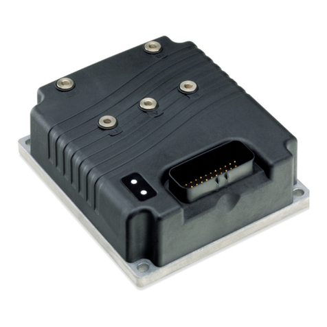
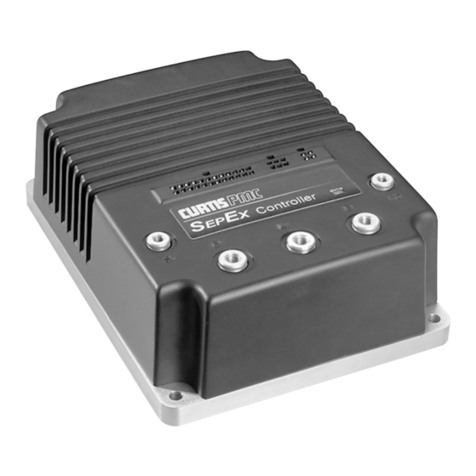
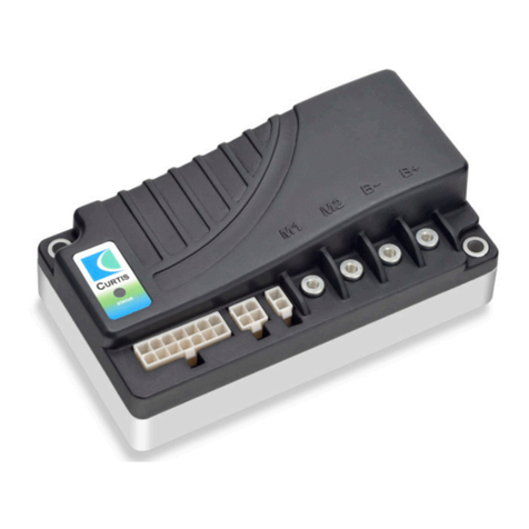
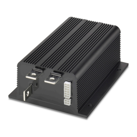
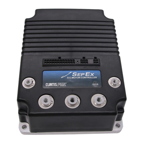
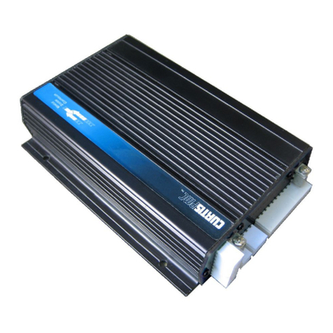
Curtis 1212 User manual

1212 Manual
1212 Manual, p/n 53112
Rev. A: July 2009
CURTIS INSTRUMENTS, INC.
200 Kisco Avenue
Mt. Kisco, New York 10549 USA
Tel. 914.666.2971
Fax 914.666.2188
www.curtisinstruments.com
© 2009 CURTIS INSTRUMENTS, INC.
DESIGN OF CURTIS PMC 1200 SERIES
CONTROLLERS PROTECTED BY U.S.
PATENT NO. 4626750.
1212
MODEL
MOTOR CONTROLLER


Curtis 1212 Manual iii
CONTENTS
1. OVERVIEW ...............................................................................1
2. INSTALLATION AND WIRING .............................................4
Mounting the Controller .....................................................4
Connections: High Current ................................................5
Connections: Low Current .................................................5
Controller Wiring: Standard Installation ............................6
Throttle Wiring ...................................................................7
Switches and Other Hardware .............................................9
3. PROGRAMMABLE PARAMETERS .......................................11
Drive Parameters ...............................................................12
Speed Parameters ...............................................................14
Throttle Parameters ...........................................................15
Current Parameters ............................................................18
Inhibit Parameters .............................................................18
Brake Parameters ...............................................................19
Horn Parameters ................................................................19
Motor Parameters ..............................................................20
BDI Parameters .................................................................21
Compensation Parameters .................................................22
Miscellaneous Parameters ..................................................22
Controller Cloning ............................................................22
4. MONITOR MENU .................................................................23
5. INITIAL SETUP ......................................................................24
6. VEHICLE PERFORMANCE ADJUSTMENT .......................27
7. DIAGNOSTICS AND TROUBLESHOOTING ....................33
8. MAINTENANCE ....................................................................38
APPENDIX A Vehicle Design Considerations
APPENDIX B Battery Discharge Indicator (BDI) Setup
APPENDIX C Programmer Operation
APPENDIX D 1212 Controller Specifications
CONTENTS

iv Curtis 1212 Manual
FIGURES
FIG. 1: Curtis 1212 electronic motor controller ....................................1
FIG. 2: Mounting dimensions, Curtis 1212 controller .........................4
FIG. 3: Standard wiring configuration ...................................................6
FIG. 4: Wiring for 5kΩ, 3-wire potentiometer .....................................7
FIG. 5: Wiring for voltage throttle .........................................................7
FIG. 6: Wiring to inhibit operation during battery charging ..............10
FIG. 7: Effect of adjusting the Throttle Map parameter .......................16
FIG. 8: Wiring for brake light ..............................................................19
FIG. C-1: Curtis 1311 handheld programmer ..................................... C-1
TABLES
TABLE 1: Programmable parameter menus ........................................11
TABLE 2-0: Status LED fault codes, Type 0 ..........................................34
TABLE 2-1: Status LED fault codes, Type 1 ..........................................35
TABLE 2-2: Status LED fault codes, Type 2 ..........................................36
TABLE 3: Troubleshooting chart ........................................................37
TABLE D-1: Specifications, 1212 controller ....................................... D-1
FIGURES / TABLES

Curtis 1212 Manual 1
1 — OVERVIEW
OVERVIEW
The Curtis enAble® 1212 motor speed controller provides precise and smooth
control of permanent magnet drive motors for battery powered vehicles. It is
designed for use in low power DME applications such as micro-scooters, mini-
scooters, foldable scooters, and low-end personal mobility vehicles. Although it
is optimized for use on modern 3-wheel and 4-wheel mobility aid scooters, its
programmable options also allow it to be used on any low power permanent
magnet motor application.
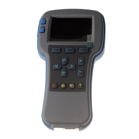
The 1212 controller is fully programmable by means of the Curtis 1311
handheld programmer. Use of the programmer offers diagnostic and test ca-
pability as well as configuration flexibility.
1
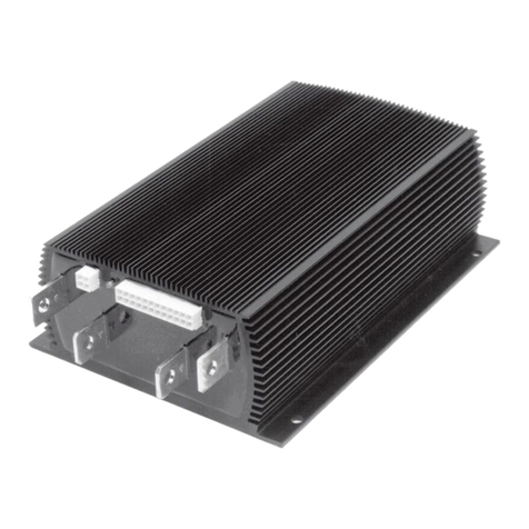
Fig. 1 Curtis 1212
electronic motor controller.
Like all Curtis motor controllers, the 1212 offers superior operator control of
the vehicle’s motor drive speed. Key features include:
Smooth and Secure Control
✓ Advanced speed regulation maintains precise speed over varied terrain,
obstacles, curbs, and ramps
✓ Linear cutback of current ensures smooth control, with no sudden loss
of power during undervoltage or overtemperature
✓ Optional speed limit potentiometer provides direct and linear control
of the maximum vehicle speed
✓ Proprietary algorithms help prevent gearbox wear while providing
smooth starts and reversals
More Features ☞

2 Curtis 1212 Manual
1 — OVERVIEW
✓ The vehicle is brought to a complete stop before the electromagnetic
brake is applied, ensuring safe and secure stops under all conditions
✓ Charger inhibit input prevents driving while charger is attached
✓ Key Off Decel function ensures a smooth “brake to stop” when the
key is turned off while driving or when a fault occurs that requires the
vehicle to stop
✓ Anti-Rollback/Roll-forward function provides smooth and safe vehicle
control on hills and ramps
✓ Internal main contactor provides secure power-off
✓ Boost current gives a brief boost of current greatly improving
transient loads such as starting on a hill, crossing thresholds, etc.
Easy Installation and Setup
✓ Industry standard footprint, mounting centers, and wiring allows
drop-in replacement of other controllers
✓ Model 1212 controllers are easily programmed with Model 1311
handheld or Model 1314 PC programmers, or can be supplied
pre-programmed
✓ Accepts all standard throttle types, including single-ended, wigwag,
and unipolar
✓ Simplified troubleshooting and diagnostics
✓ Standard Mini-Fit Molex Jr. and Faston terminals provide proven,
robust wiring connections
Valuable Additional Features
✓ Optional Push Switch input releases the brake and allows the motor
to free-wheel
✓ Push-Too-Fast feature restricts the vehicle’s speed while it is being
pushed, even with the key off or the batteries disconnected
✓ Automatic compensation for changes in motor condition to ensure
optimum drive preformance at all times
✓ Multi-mode provides for two distinct and programmable control
modes (indoor/outdoor)
✓ Power Saver function prevents the controller draining the battery
when the vehicle is inactive
✓ Battery Discharge Indicator output
✓ Optional Speed Inhibit input offers flexibility to reduce speed or
prevent drive under certain conditions, such as when the seat is lifted
✓ Adjustable brake hold voltage reduces heating of the brake coil
✓ Reverse Beeper function alerts bystanders
✓ Electronics sealed to IPX5
Curtis 1212 Manual 3
Robust Safety and Reliability
✓ High RF immunity prevents speed variation and shutdowns in noisy
RF environments
✓ Controller power circuits and microprocessor software are
continuously monitored for proper operation
✓ On power-up, system automatically checks the throttle, brake,
and associated wiring, and disables drive if a fault is found
Meets or Complies with Relevant US and International regulations
✓ Designed to meet EN 12184, EN 55022, IEC 61000, and ISO-7176-14
✓ FDA documentation filed
✓ TÜV certification pending.
Familiarity with your Curtis controller will help you install and operate it
properly. We encourage you to read this manual carefully. If you have ques-
tions, please contact the Curtis office nearest you.
1 — OVERVIEW
Working on electric vehicles is potentially dangerous. You should protect
yourself against runaways and high current arcs:
RUNAWAYS — Some conditions could cause the vehicle to run out of control.
Disconnect the motor or jack up the vehicle and get the drive wheels off
the ground before attempting any work on the motor control circuitry.
HIGH CURRENT ARCS — Always open the battery circuit before working on
the motor control circuit. Wear safety glasses, and use properly insulated
tools to prevent shorts.

4 Curtis 1212 Manual
INSTALLATION AND WIRING
MOUNTING THE CONTROLLER
The 1212 controller can be oriented in any position, but the location should
be carefully chosen to keep the controller clean and dry. If a clean, dry
mounting location cannot be found, a cover must be used to shield the
controller from water and contaminants.
The outline and mounting hole dimensions are shown in Figure 2. The
controller should be mounted by means of the two mounting holes at the op-
posing corners of the heatsink, using M4 (#8) screws.
2
2 — INSTALLATION & WIRING
Fig. 2 Mounting
dimensions, Curtis 1212
controller.
Dimensions in millimeters and (inches)
✭
You will need to take steps during the design and development of your
end product to ensure that its EMC performance complies with applicable
regulations; suggestions are presented in Appendix A.

Curtis 1212 Manual 5
2 — INSTALLATION & WIRING
J1 Pin 1 pot wiper
J1 Pin 2 pot high
J1 Pin 3 horn switch
J1 Pin 4 mode switch (open=M1, closed=M2)
J1 Pin 5 keyswitch input (KSI)
J1 Pin 6 speed inhibit
J1 Pin 7 B+
J1 Pin 8 pot low
J1 Pin 9 speed pot
J1 Pin 10 status LED
J1 Pin 11 BDI
J1 Pin 12 reverse switch
J1 Pin 13 B-
J1 Pin 14 push switch
CONNECTIONS: High Current
Four 1/4" Faston terminals are provided for the high current connections.
The motor connections (M1, M2) and battery
connections (B+, B-) have one terminal each.
CONNECTIONS: Low Current
The low current logic control connections are provided by a 14-pin connector.
The mating connector is a Molex Mini-Fit-Jr. receptacle p/n 39-01-2140 with
appropriate 45750-series crimp terminals.
A 4-pin low power connector is provided for the programmer and
the battery charger. The mating connector is a Molex Mini-Fit-Jr.
receptacle p/n 39-01-2040 with appropriate 45750-series crimp
terminals. (A mating connector is provided with the 1311 handheld
programmer.).
A 2-pin low power connector is provided for the electromagnetic brake.
The mating connector is a Molex Mini-Fit-Jr. receptacle p/n 39-01-2020
with appropriate 45750-series crimp terminals.
1 2
3 4
J1
J2
J2 Pin 1 Rx
J2 Pin 2 B-
J2 Pin 3 Tx/charge inhibit
J2 Pin 4 B+
J3 Pin 1 Brake +
J3 Pin 2 Brake -
1
2
J3
M1 M2 B- B+
1 2 3 4 5 6 7
8 9 10 11 12 13 14

6 Curtis 1212 Manual
2 — INSTALLATION & WIRING
Fig. 3 Standard wiring configuration, Curtis 1212 controller.
WIRING: STANDARD INSTALLATION
The wiring diagram presented in Figure 3 shows a typical installation. This
installation is shown with a single-ended 3-wire 5kΩ potentiometer throttle
and a reverse switch. With wigwag throttles, a reverse switch is not used and
Pin 12 is left unconnected.
The optional speed inhibit input can be wired into the circuit in various
ways; in the standard installation shown here, it is B- active (Speed Inhibit
parameter set to 0).
The J2 connector can be used interchangeably for the programmer or
for the battery charger.

Curtis 1212 Manual 7
2 — INSTALLATION & WIRING: Throttle
THROTTLE WIRING
Either a 3-wire potentiometer throttle or a voltage throttle can be used. The
controller can accept a single-ended, inverse single-ended, wigwag, inverse
wigwag, or unipolar input signal from the throttle, depending on how the
Throttle Type parameter is programmed; see page 15.
Throttle wiring is described in the following text. If the throttle you are
planning to use is not covered, contact the Curtis office nearest you.
5kΩ, 3-Wire Potentiometer
A 5kΩ, 3-wire potentiometer is shown in the wiring diagram (Figure 3) as
well as in Figure 4. With this throttle, the controller can be programmed for
a Throttle Type 0–4 input signal; see page 15.
Fig. 4 Wiring for 3-wire,
5k
Ω
potentiometer throttle.
For wigwag, inverted wigwag, and unipolar applications, the pot can be
correctly centered within the controller’s neutral band by using the throttle
autocalibration feature (see page 18).
The controller provides full pot fault protection against open or shorted
wires anywhere in the throttle assembly. The overall pot resistance should be
5kΩ ±20%. Values outside this range will trigger a fault condition. If a pot fault
occurs while the vehicle is moving, the controller will decelerate the vehicle to
a smooth stop using the decel rate set by the Key Off Decel parameter. If the
fault is corrected while the throttle is still applied, an HPD fault will be issued
and driving is disabled until throttle is reduced to neutral.
Voltage Throttle
Wiring for a voltage throttle is shown in Figure 5. With this throttle, the con-
troller can be programmed for a Throttle Type 5–9 input signal; see page 15.
1 2 3 4 5 6 7
8 9 10 11 12 13 14
Fig. 5 Wiring for voltage
throttle.
1 2 3 4 5 6 7
8 9 10 11 12 13 14
+
-
VOLTAGE
THROTTLE
Pot Wiper input (Pin 1)
B-
The PotHigh and PotLow parameters are used to set the voltage range of
these throttles. If the pot wiper voltage is higher than the programmed PotHigh

8 Curtis 1212 Manual
2 — INSTALLATION & WIRING: Throttle
value or lower than the programmed PotLow value, the controller will issue
an out-of-range throttle fault. In order for the controller to be able to detect
out-of-range throttle faults, the throttle must have a range within the limits
of 0.4–4.6 V.
Note: If a 0–5V throttle is used, it is the responsibility of the OEM to
provide appropriate throttle fault detection.
Speed Limit Pot
A speed limit pot allows the operator to adjust the speed of the vehicle at full
throttle. The speed limit pot should be sized so that it does not affect throttle in-
put resistance and thus the throttle response; a 100kΩ pot is recommended.
The speed limit pot is at its maximum speed setting when its wiper is
shorted to the throttle’s pot high connection (Pin 2). When the speed limit pot
is in its maximum speed position, the vehicle’s speed at full throttle corresponds
to the programmed maximum speed setting.
The speed limit pot is at its minimum speed setting when its wiper is
shorted to the throttle’s pot low connection (Pin 8). When the speed limit pot
is in its minimum speed position, the vehicle’s speed at full throttle corresponds
to the programmed minimum speed setting. For information on the program-
mable speed parameters, see Section 3.
The speed limit pot varies the vehicle’s speed linearly over the range be-
tween the minimum and maximum speed settings in each mode, in forward
and in reverse.
If a speed limit pot is not used, the Speed Limit Pot parameter should
be programmed Off to disable the fault check at the speed limit pot.

Curtis 1212 Manual 9
SWITCHES AND OTHER HARDWARE
Keyswitch
The vehicle should have a master on/off switch to turn the system off when
not in use. The keyswitch provides logic power for the controller and for the
other control input switches. It must be sized to carry the 150 mA quiescent
logic current plus the current necessary to drive the precharge function (1.5 A
for 0.5 seconds) and the status LED, horn, and any other accessories powered
from the keyswitch circuit.
Push Switch
A push switch can be used to electrically release the electromagnetic brake and
inhibit driving. Maximum speed in push mode is set by the Push Max Speed
parameter. If a push input is applied at power-up, it will not be acknowledged
until it has been released and reapplied. The vehicle can enter push mode only
when it is in neutral or when the controller is not powered on.
Brake Release Switch (Brake Coil Disable Switch)
If a brake release lever is used to release the electromagnetic brake mechanically,
a brake coil disable switch is recommended. This switch opens the electromag-
netic brake coil circuit when the mechanical brake release lever releases the
brake from the motor shaft. The open brake coil circuit will register as a fault,
inhibiting controller operation if an operator attempts to drive the vehicle with
the brake mechanically released. This safety feature ensures that the vehicle
cannot be driven when the brake cannot be engaged.
Mode Switch
A mode switch is used to select operation in Mode 1 or Mode 2. Typically,
Mode 1 is programmed for slower indoor driving and Mode 2 for faster outdoor
driving; see Speed menu. The controller is in Mode 2 when the mode switch is
in the On position (input connected to B+). Leaving the mode input floating
or actively switching it Off (pulling it to B-) puts the controller in Mode 1.
Battery Discharge Indicator (BDI)
The 1212 controller can drive a BDI panel meter to show the battery pack’s
state of charge as a percentage of the amp-hour capacity of the batteries. The
batteries must be put through a full charge cycle with the controller installed
before the BDI will begin operation.
Charger Inhibit
Typically, battery chargers have a dedicated third terminal that automatically
provides inhibit. When the charger is connected to the controller’s J2 con-
nector, the controller disables the drive functions and engages the EM brake
while the charger is connected. Inhibit is provided through J2 Pin 3; see wiring
diagram (Figure 3, page 6). The charger inhibit automatically powers up the
controller without the keyswitch on so that BDI can be tracked during charge.
2 — INSTALLATION & WIRING: Switches, etc.

10 Curtis 1212 Manual
After BDI is 100% reset, power is totally shut off (no current used) to avoid
draining the battery.
If your battery charger does not have a dedicated inhibit terminal, you
must wire B- to J2 Pin 3, as shown in Figure 6.
2 — INSTALLATION & WIRING: Switches, etc.
Fig. 6 Wiring to inhibit
operation during battery
charging (for battery
chargers without a
dedicated inhibit
terminal).
12
3 4
Speed Inhibit
A speed inhibit switch can be used to limit drive speed, or even to prevent
drive altogether, in certain conditions; see Inhibit menu. The maximum speed
allowed during inhibit operation is also set in the Inhibit menu, with a setting
of zero preventing drive.
Status LED
The 1212 controller has the capability to drive a panel indicator LED, which
can be used to tell the operator, at a glance, the controller’s status. This LED
always indicates whether the controller is powered on or off. It will also provide
diagnostics information via flash codes (see Section 7).
If a status LED is used, it should be installed with the proper resistor in
series. The controller’s LED driver is capable of a maximum current of 15 mA.
The recommended resistor—designed to limit driver current to 15 mA when
active—is 2.4 kΩ, 0.5 W. Alternatively, an LED with a built-in resistor can
be used; it should be rated for 24V operation.
Horn
The controller’s horn driver—Pin 3—is designed to drive a low current dc horn
at 1 Hz. The horn sounds a warning when the reverse direction is selected and
when the throttle autocalibration feature is being used. The horn driver sinks a
maximum current of 15 mA. Using a horn with a higher current requirement
will damage and disable the driver.
The horn driver can be used to drive a brake light instead of a horn; see
Brake menu.
Circuitry Protection Devices
To protect the control wiring from accidental shorts, a low current fuse
(appropriately sized for the maximum control circuit current draw) should be
connected in series with the B+ logic supply. A fuse is also recommended in
the high power circuit from the battery to the controller’s B+ terminal. This
fuse will protect the power system from external shorts and should be sized
appropriately for the maximum rated current of the controller.

Curtis 1212 Manual 11
3 — PROGRAMMABLE PARAMETERS
PROGRAMMABLE PARAMETERS
The 1212 controller has a number of parameters that can be programmed
using a Curtis 1311 handheld programmer or Curtis 1314 PC Programming
Station. These programmable parameters allow the vehicle’s performance to be
customized to best fit the needs of individual vehicle operators.
For information on programmer operation, see Appendix C.
For information on how to use the parameters to optimize performance,
see Section 6.
The programmable parameters are grouped hierarchically into menus, as shown
in Table 1. Not all of these parameters are displayed on all controllers; the list
for any given controller depends on its specifications.
3
THROTTLE MENU ......................p. 15
—Type
—PotHigh
—PotLow
—Neutral Deadband
—Throttle Max
—HPD
—Speed Limit Pot
—Throttle Map
—Tremor Suppression
—Calibration
CURRENT MENU ....................... p. 18
—Main Current Limit
—Braking Current Limit
—Boost Current
—Boost Time
INHIBIT MENU ........................... p. 18
—Type
—Speed
BRAKE MENU ............................ p. 19
—Delay
—Fault Check
—Hold Voltage
—Brake Light
HORN MENU ............................ p. 19
—Fault Beep
—Reverse Beep
—Beep Constant
MOTOR MENU ............................ p. 20
—System Resistance
—Resistance Auto Comp
—Auto Comp Current Limit
—Speed Scaler
—Current Rating
—Max Current Time
—Cutback Gain
BDI MENU ............................ p. 21
—Full Voltage
—Empty Voltage
—Full Charge Voltage
—Start Charge Voltage
—Reset Voltage
—Low BDI Level
—Low BDI Max Speed
—Charge Factor
—Discharge Factor
COMPENSATION MENU ............... p. 22
—IR Comp
—Anti-Rollback Comp
MISCELLANEOUS MENU ............. p. 22
—Sleep
—Fault Code Type
—Reset Drive Time
DRIVE MENU ............................ p. 12
—Accel Max Speed
—Accel Min Speed
—Decel High Speed
—Decel Low Speed
—Rev Accel Max Speed
—Rev Accel Min Speed
—Rev Decel High Speed
—Rev Decel Low Speed
—Key Off Decel
—E Stop Decel
—E Stop Pause
—Soft Start
—Gear Soften
—Creep Speed
—Push Max Speed
—Soft Stop Speed
—Speed ........................... p. 14
—Mode 1
—Max Speed
—Min Speed
—Rev Max Speed
—Rev Min Speed
—Mode 2
—Max Speed
—Min Speed
—Rev Max Speed
—Rev Min Speed
Table 1 Programmable Parameter Menus: 1311 Programmer

12 Curtis 1212 Manual
DRIVE MENU
ALLOWABLE
PARAMETER RANGE DESCRIPTION
Accel Max Speed 0.2–8.0 sec Sets the rate (in seconds) at which the speed command increases
when throttle is applied with the speed limit pot is in its maximum speed
position, and the vehicle is traveling forward. Larger values represent
slower response.
Note: Allowable range is restricted by the Accel Min Speed setting.
Accel Min Speed 0.2–8.0 sec Sets the rate (in seconds) at which the speed command increases
when throttle is applied while the speed limit pot is in its minimum speed
position, and the vehicle is traveling forward. Larger values represent
slower response
Note: Allowable range is restricted by the Accel Max Speed setting.
Decel High Speed 0.2–8.0 sec Sets the rate (in seconds) that is used to slow down the vehicle when it
is traveling forward at high speed and throttle is reduced. Larger values
represent slower response.
Note: Allowable range is restricted by the Decel Low Speed setting.
Decel Low Speed 0.2–8.0 sec Sets the rate (in seconds) that is used to slow down the vehicle when it
is traveling forward at low speed and throttle is reduced. Larger values
represent slower response.
Note: Allowable range is restricted by the Decel High Speed setting.
Rev Accel Max Speed 0.2–8.0 sec Sets the rate (in seconds) at which the speed command increases
when throttle is applied while the speed limit pot is in its maximum speed
position, and the vehicle is traveling in reverse. Larger values represent
slower response.
Note: Allowable range is restricted by Rev Accel Min Speed setting.
Rev Accel Min Speed 0.2–8.0 sec Sets the rate (in seconds) at which the speed command increases
when throttle is applied while the speed limit pot is in its minimum speed
position, and the vehicle is traveling in reverse. Larger values represent
slower response.
Note: Allowable range is restricted by Rev Accel Max Speed setting.
Rev Decel High Speed 0.2–8.0 sec Sets the rate (in seconds) that is used to slow down the vehicle when it
is traveling in reverse at high speed and throttle is reduced. Larger values
represent slower response.
Note: Allowable range is restricted by Rev Decel Low Speed setting.
Rev Decel Low Speed 0.2–8.0 sec Sets the rate (in seconds) that is used to slow down the vehicle when it
is traveling in reverse at low speed and throttle is reduced. Larger values
represent slower response.
Note: Allowable range is restricted by Rev Decel High Speed setting.
Key Off Decel 0.2–4.0 sec Sets the rate (in seconds) that is used to slow down the vehicle at key-off
or in the event of a major fault.
3 — PROGRAMMABLE PARAMETERS: Drive Parameters

Curtis 1212 Manual 13
DRIVE MENU, cont’d
ALLOWABLE
PARAMETER RANGE DESCRIPTION
E Stop Decel 0.2–4.0 sec Sets the rate (in seconds) that is used to slow down the vehicle during
emergency reverse, i.e., when a throttle command >80% in the reverse
direction is given while the vehicle is moving forward. This gives the
operator a way to stop more quickly when unexpected conditions arise.
E Stop Pause 0.0–1.0 sec Sets a pause before reversing direction after an emergency reverse stop.
This gives the operator time to return the throttle to neutral without moving
backwards.
Soft Start 0–100 % This parameter can be used to soften the bump associated with gear
slack in the transaxle when throttle is applied from the neutral state. Larger
values provide a softer slack take-up.
Gear Soften 0–100 % This parameter is intended to soften the bump associated with gear slack
in the transaxle when throttle is released and then reapplied while the
vehicle is still moving. Larger values provide a softer slack take-up.
Creep Speed 0–10 % Creep Speed helps to prevent vehicle rollback on inclines when the brake
is released with very little throttle applied. It is activated when the throttle
request exceeds the throttle deadband threshold.
Push Max Speed 25–50 % Sets the maximum speed at which the vehicle can be pushed.
When the vehicle is powered on and in neutral, it enters the push
mode when the push button is activated. The electromagnetic brake is
released, driving is inhibited, and speed is limited to Push Max Speed.
When the vehicle is not powered on and the brake is mechanically
released to enable pushing, Push Max Speed still applies. Once sufficient
voltage is generated by the motor, speed will be limited by the controller.
Soft Stop Speed 0–30 % Sets the speed at which a gentler deceleration is initiated when the throttle
is released to neutral; larger values start the soft stop deceleration sooner.
3 — PROGRAMMABLE PARAMETERS: Drive Parameters

14 Curtis 1212 Manual
3 — PROGRAMMABLE PARAMETERS: M1/M2 Speed Parameters
SPEED MENU
ALLOWABLE
PARAMETER RANGE DESCRIPTION
M1/M2 Max Speed 0–100 % During forward operation, defines the requested speed at full throttle when
the speed limit pot is in its maximum speed position.
Note: Allowable range is restricted by the M1/M2 Min Speed setting.
M1/M2 Min Speed 0–100 % During forward operation, defines the requested speed command at full
throttle when the speed limit pot is in its minimum speed position. Min
Speed cannot be set higher than the programmed Max Speed.
Note: Allowable range is restricted by the M1/M2 Max Speed setting.
Note: For this parameter to apply, a speed limit pot must be installed
in parallel with the throttle and the Speed Limit Pot parameter must be
programmed On (see Throttle menu).
M1/M2 Rev Max Speed 0–100 % During reverse operation, defines the requested speed at full throttle when
the speed limit pot is in its maximum speed position.
Note: Allowable range is restricted by M1/M2 Rev Min Speed setting.
M1/M2 Rev Min Speed 0–100 % During reverse operation, defines the requested speed command at full
throttle when the speed limit pot is in its minimum speed position. Rev Min
Speed cannot be set higher than the programmed Rev Max Speed.
Note: Allowable range is restricted by M1/M2 Rev Max Speed setting.
Note: For this parameter to apply, a speed limit pot must be installed
in parallel with the throttle and the Speed Limit Pot parameter must be
programmed On (see Throttle menu).
SPEED MODES
The 1212 controller’s Multi-Mode™ feature allows operation in two distinct
modes: Mode 1 and Mode 2. These modes can be programmed to provide two
different sets of operating characteristics, which can be useful for operation in
different conditions. For example, Mode 1 could be programmed such that the
vehicle moves slowly for precise, indoor maneuvering, and Mode 2 programmed
for higher speed, long distance travel outdoors.
The controller is in Mode 2 when the mode switch is in the On position
(input connected to B+). Leaving the mode input floating or actively switching
it Off (pulling it to B-) puts the controller in Mode 1.
The Speed menu allows the maximum speed in forward and reverse to
be set independently in Mode 1 and Mode 2. The position of the speed limit
pot determines whether the programmed Max Speed or Min Speed—or a speed
between these two programmed speeds—is in effect. Speed is varied linearly
over the range between the two speeds in each mode, in forward and reverse.

Curtis 1212 Manual 15
3 — PROGRAMMABLE PARAMETERS: Throttle Parameters
THROTTLE MENU
ALLOWABLE
PARAMETER RANGE DESCRIPTION
Type 0–9 The 1212 controller can accept inputs from both 5kΩ, 3-wire pot throttles
and voltage throttles. Set the throttle type parameter to match the throttle
used in your application.
5k
Ω
, 3-wire pot throttles
0 = wigwag
1 = inverted wigwag
2 = single-ended; neutral when wiper at PotLow
3 = inverted single-ended; neutral when wiper at PotHigh
4 = unipolar.
Voltage throttles
5 = wigwag
6 = inverted wigwag
7 = single-ended; neutral when wiper ≤ PotLow
8 = inverted single-ended voltage; neutral when wiper ≥ PotHigh
9 = unipolar
Note: If Throttle Type 5–9 is used, see note on page 8.
PotHigh 3–5 V Sets the maximum voltage for voltage throttles (Types 5–9).
(For 5kΩ, 3-wire pot throttles, PotHigh is determined by the throttle itself.)
PotLow 0–2 V Sets the minimum voltage for voltage throttles (Types 5–9).
(For 5kΩ, 3-wire pot throttles, PotLow is determined by the throttle itself.)
Neutral Deadband 5–30 % Sets the throttle range the controller interprets as neutral. Increasing the
parameter setting increases the neutral range. This parameter allows the
neutral deadband to be defined wide enough to ensure the controller goes
into neutral when the throttle is released.
Guidelines for adjusting this parameter are provided in Section 5.
Throttle Max 40–100 % Sets the pot wiper voltage required to produce 100% controller output.
Increasing the Throttle Max setting reduces the wiper voltage required,
and therefore reduces the stroke necessary to produce full output. This
feature allows reduced-range throttle assemblies to be used.
Guidelines for setting Throttle Max are provided in Section 5.
HPD On/Off When programmed On, vehicle drive is inhibited if a throttle command
outside the neutral deadband is issued before the controller is powered up.
Drive will continue to be inhibited until the throttle is returned to within the
neutral deadband. If the HPD fault is not cleared within 10 seconds,
a wiring fault is declared and a power cycle is required.
Speed Limit Pot On/Off This parameter is used to enable/disable the speed limit pot. If no speed
limit pot is used, set Speed Limit Pot to Off.

16 Curtis 1212 Manual
3 — PROGRAMMABLE PARAMETERS: Throttle Parameters
THROTTLE MENU, cont’d
ALLOWABLE
PARAMETER RANGE DESCRIPTION
Throttle Map 20–80 % The throttle map parameter adjusts the static throttle map. The parameter
setting corresponds to the throttle command at half throttle, as shown in
Figure 7.
A setting of 50% provides linear response. Values below 50% reduce
the throttle command at low throttle positions, providing enhanced slow
speed maneuverability. Values above 50% give the vehicle a faster, more
responsive feel at low throttle positions.
Tremor Suppression 0–100 % This parameter can be used to limit the controller’s response to sharp
throttle movements, such as movements resulting from hand tremors.
Larger values will provide a steadier ride, but they also result in more
sluggish response to throttle request. There is thus a trade-off between
crispness of response (low Tremor Suppression settings) and steady
speed in the presence of tremors (high settings).
Fig. 7 Effect of throttle
adjustment parameters.
These four parameters
determine the controller’s
response to throttle position,
in forward and reverse.
Here,
Deadband = 10%
Throttle Max = 90%
Creep = 0%.
This manual suits for next models
1
Table of contents
Other Curtis Controllers manuals

Curtis
Curtis 1204M User manual

Curtis
Curtis MultiMode 1228 User manual

Curtis
Curtis 1226 User manual

Curtis
Curtis 1268 User manual

Curtis
Curtis 1204 User manual

Curtis
Curtis 1313 User manual

Curtis
Curtis PMC 1204 Series User manual

Curtis
Curtis 1298 User manual

Curtis
Curtis 1232E User manual

Curtis
Curtis 1268 User manual

Curtis
Curtis MultiMode 1214-8 User manual

Curtis
Curtis 1232E User manual

Curtis
Curtis 1310 User manual

Curtis
Curtis 1232E User manual

Curtis
Curtis 1268-5403 User manual

Curtis
Curtis 1268-5411 User manual

Curtis
Curtis MultiMode 1207B User manual

Curtis
Curtis 1220 User manual

Curtis
Curtis 1297 User manual

Curtis
Curtis 1239E User manual