TROUBLESHOOTING GUIDE
Applies to both Automatic and Manual operation unless indicated otherwise.
TABLE 1: MODEL 56 TROUBLESHOOTING GUIDE
HUMIDIFIER OPERATES CONSTANTLY
• If the humidity level in the home is less than the knob setting, the
Humidier Control will operate the Humidier until the humidity level is
higher than the knob setting.
• In the TEST mode, verify unit will operate for approximately one minute.
• Check the resistance of the Outdoor Temperature Sensor as instructed
above.
• Make sure the Outdoor Temperature Sensor is mounted completely
outside the house on the North, East, or West side of the house and out
of direct sunlight (automatic mode only).
• Rotate the Humidier Control knob counterclockwise to the OFF position,
and observe whether the humidier turns off. If the humidier still
operates in the OFF position, perform the following:
1. Check summary wiring diagram for correct Humidier Control
Installation.
2. Remove wires from Humidier Control’s H terminals. If Humidier
continues to operate, replace solenoid valve.
HUMIDIFIER OR HUMIDIFIER CONTROL “CHATTERS” OR CLICKS ON AND OFF
RAPIDLY
• Check for steady 22 VAC to 30 VAC with voltmeter.
• Make sure Outdoor Temperature Sensor wiring is not run alongside wires
carrying high voltage (120 VAC or higher) (automatic mode only).
RED DIAGNOSTIC LIGHT IS ON
• Check that the wiring is correct.
• Measure the resistance of the Outdoor Temperature Sensor by removing
the leads from the terminal and measuring the resistance across the
wires with an ohmmeter. Conrm the reading with the temperature in
TABLE 2. (For Manual operation, verify that the resistance across the leads
of the Manual Mode Resistor Case is between 44,000 and 48,000 ohms).
BYPASS
POWER
R
24V
C ODTH
90-1012
B2202617D • 10005402 • 08.23
© 2023 AprilAire | aprilairepartners.com | 800.334.6011
AprilAire reserves the right to change specications without notice.
HUMIDIFIER CONTROL TEMPLATE
4-3/4” x 3”
1. Cut out template along edges.
2. Place template on the return plenum upstream of (before)
the humidier connection.
3. Trace outside edges of template.
4. Remove template and accurately cut plenum opening.
5. Using 4 sheet metal screws, install Humidier Control in
plenum opening.
TABLE 2
Outdoor Temperature (°F) -30 -20 -10 010 20 30 40 50 60 70 80 90 100
Resistance (kΩ) 230.6 163.8 117.6 85.4 62.6 46.3 34.6 26.1 19.9 15.3 11.9 9.4 7.4 5.9
TABLE 1: MODEL 56 TROUBLESHOOTING GUIDE
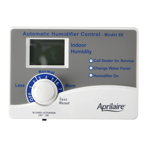
“CHANGE WATER PANEL” INDICATOR IS LIT
• Call your installer to have your water panel changed, or visit your
installer to purchase a new AprilAire water panel. Follow the instructions
on the water panel box.
HUMIDIFIER DOES NOT OPERATE IN “TEST” MODE
• Make sure furnace blower is operating and thermostat is calling for
heat.
• Make sure the Outdoor Temperature Sensor is connected to the ODT
terminals of the control. (For Manual operation, make sure Manual Mode
Resistor Case is in place.)
• Check main wiring diagram for correct Humidier Control installation.
• If connected to a Model 400 Humidier, make sure both oats in the
bottom of the scale control insert are in the down position. If necessary,
dump out water to lower oats.
• Check voltage at Humidier Control R and C terminals. Voltage should
be 22 VAC minimum to 30 VAC maximum.
• Check Model 50 Current Sensing Relay (if used) for correct installation
(see Model 50 instructions). Do not use Model 50 Relay in transformer
circuit or R and C circuit of Humidier Control. Model 50 relay is to be
used in the H circuit only.
• In TEST mode, humidier will operate for 1 minute only. DO NOT LEAVE IN
TEST MODE AS HUMIDIFIER WILL NOT OPERATE.
• Make sure saddle valve is open.
HUMIDIFIER OPERATES ONLY IN “TEST” MODE
• If outdoor temperature is greater than 60°F or less than -30°F, the
Humidier Control will only operate in the TEST mode (for one minute).
• If the humidity level in the home is higher than the knob setting, the
Humidier Control will not operate the Humidier.
• Check the resistance of the sensor by removing the leads of the
Outdoor Temperature Sensor from the terminals and measuring the
resistance across the wires with an ohmmeter. Compare reading to
outdoor temperature in TABLE 2 . (For Manual operation, verify that
resistance across the leads of Manual Mode Resistor Case is between
44,000 and 48,000 ohms).
• Make sure the Outdoor Temperature Sensor is mounted completely
outside the house on the North, East, or West side of the house and out
of direct sunlight (automatic mode only).
• If Outdoor Temperature Sensor is mounted in fresh air intake duct,
make sure the probe is no more than 36 inches from the outside wall
(automatic mode only).
• Make sure the Outdoor Temperature Sensor is located at least 3 feet
away from all exhaust vents (automatic mode only).
CUT OUT TEMPLATE

